EP0592020B1 - A cutting oil supply device for a tap - Google Patents
A cutting oil supply device for a tap Download PDFInfo
- Publication number
- EP0592020B1 EP0592020B1 EP93202225A EP93202225A EP0592020B1 EP 0592020 B1 EP0592020 B1 EP 0592020B1 EP 93202225 A EP93202225 A EP 93202225A EP 93202225 A EP93202225 A EP 93202225A EP 0592020 B1 EP0592020 B1 EP 0592020B1
- Authority
- EP
- European Patent Office
- Prior art keywords
- cutting oil
- cup
- supplying device
- oil supplying
- work
- Prior art date
- Legal status (The legal status is an assumption and is not a legal conclusion. Google has not performed a legal analysis and makes no representation as to the accuracy of the status listed.)
- Expired - Lifetime
Links
Images


Classifications
-
- B—PERFORMING OPERATIONS; TRANSPORTING
- B23—MACHINE TOOLS; METAL-WORKING NOT OTHERWISE PROVIDED FOR
- B23Q—DETAILS, COMPONENTS, OR ACCESSORIES FOR MACHINE TOOLS, e.g. ARRANGEMENTS FOR COPYING OR CONTROLLING; MACHINE TOOLS IN GENERAL CHARACTERISED BY THE CONSTRUCTION OF PARTICULAR DETAILS OR COMPONENTS; COMBINATIONS OR ASSOCIATIONS OF METAL-WORKING MACHINES, NOT DIRECTED TO A PARTICULAR RESULT
- B23Q11/00—Accessories fitted to machine tools for keeping tools or parts of the machine in good working condition or for cooling work; Safety devices specially combined with or arranged in, or specially adapted for use in connection with, machine tools
- B23Q11/10—Arrangements for cooling or lubricating tools or work
-
- Y—GENERAL TAGGING OF NEW TECHNOLOGICAL DEVELOPMENTS; GENERAL TAGGING OF CROSS-SECTIONAL TECHNOLOGIES SPANNING OVER SEVERAL SECTIONS OF THE IPC; TECHNICAL SUBJECTS COVERED BY FORMER USPC CROSS-REFERENCE ART COLLECTIONS [XRACs] AND DIGESTS
- Y10—TECHNICAL SUBJECTS COVERED BY FORMER USPC
- Y10T—TECHNICAL SUBJECTS COVERED BY FORMER US CLASSIFICATION
- Y10T408/00—Cutting by use of rotating axially moving tool
- Y10T408/44—Cutting by use of rotating axially moving tool with means to apply transient, fluent medium to work or product
-
- Y—GENERAL TAGGING OF NEW TECHNOLOGICAL DEVELOPMENTS; GENERAL TAGGING OF CROSS-SECTIONAL TECHNOLOGIES SPANNING OVER SEVERAL SECTIONS OF THE IPC; TECHNICAL SUBJECTS COVERED BY FORMER USPC CROSS-REFERENCE ART COLLECTIONS [XRACs] AND DIGESTS
- Y10—TECHNICAL SUBJECTS COVERED BY FORMER USPC
- Y10T—TECHNICAL SUBJECTS COVERED BY FORMER US CLASSIFICATION
- Y10T408/00—Cutting by use of rotating axially moving tool
- Y10T408/50—Cutting by use of rotating axially moving tool with product handling or receiving means
-
- Y—GENERAL TAGGING OF NEW TECHNOLOGICAL DEVELOPMENTS; GENERAL TAGGING OF CROSS-SECTIONAL TECHNOLOGIES SPANNING OVER SEVERAL SECTIONS OF THE IPC; TECHNICAL SUBJECTS COVERED BY FORMER USPC CROSS-REFERENCE ART COLLECTIONS [XRACs] AND DIGESTS
- Y10—TECHNICAL SUBJECTS COVERED BY FORMER USPC
- Y10T—TECHNICAL SUBJECTS COVERED BY FORMER US CLASSIFICATION
- Y10T408/00—Cutting by use of rotating axially moving tool
- Y10T408/55—Cutting by use of rotating axially moving tool with work-engaging structure other than Tool or tool-support
- Y10T408/561—Having tool-opposing, work-engaging surface
Definitions
- This invention relates to a cutting oil supplying device according to the preamble of claim 1.
- the known device has the drawback that excess oil can be taken out of the cup by the tap and that the work is smeared with oil.
- the object of the invention is to obviate this drawback and to provide a cutting oil supplying device which allows for a cleaning-free tapping operation.
- the wiping means wipes off excess oil and also metal particles from the tap, so that subsequent cleaning of the work is not necessary.
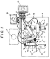
- Fig.1 is a plan view of a cutting oil supplying device.
- Fig.2 is a side view of the cutting oil supplying device of Fig.1.
- Fig.3 is a perspective view of a work supporter.
- Fig.4 is a plan view of the work supporter of Fig.3, while without a cap.
- Fig.5 is a side view of the work supporter of Fig.4.
- Fig.6 is a vertical section showing an essential part of the work supporter of Fig.3.
- Fig.7 is a plan view of a work supporter of another embodiment, while without a cap.
- Fig.8 is a side view of the work supporter of Fig.7.
- Fig.9 is a vertical section showing an essential part of the work supporter of Fig.7, while with the cap.
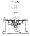
- Fig.10 is a sectional view showing a cutting oil supplying device of another embodiment.
- Fig.11 shows a cup for cutting oil: (a) shows a plan view thereof and (b) shows a vertical section thereof.
- Fig.12 shows a filter: (a) shows a plan view thereof and (b) shows a vertical section thereof.
- Fig.13 shows a ring brush: (a) shows a plan view and (b) shows a vertical section thereof.
- reference numeral 1 denotes a workbench which is fixed to a supporter 2 horizontally by fastening means 3.
- the workbench 1 is a plate having several mounting holes 5 for securing means 19a which secures a work supporter 4,4...to the workbench 1.
- a multiple spindle tapping machine 6 having four taps is installed at one side of the workbench 1.
- the work supporter 4 is fixed adjustably to the workbench 1 and positioned at a tapping position. As shown in Figs.3 to 6, the work supporter 4 has a body 7 which is substantially a rectangular solid. One end portion 8 of the body has a lower upper surface and a cylindrical hole 9a is provided in the end portion 8 which serves as a cup 9 for cutting oil.
- the cup 9 is filled with a flexible porous member 10 such as a sponge.
- a circular shaped cap having a hole for receiving the tap is capped on the upper portion of the cup 9.
- a cutting oil supplying path 12 is connected to a lower portion of the cup 9 and extends through the body to a lower portion of the other end of the body 7.
- An oil tank 15 is mounted on a stay 14 which is connected to the workbench 1 by securing means 13.
- the cutting oil supplying path 12 is connected to the oil tank 15 by a flexible pipe 16 and a valve 17.
- One side of a bottom of the body 7 extends to form an arm 18 having an elongate groove 19.
- the work supporter 4 is fixed adjustably to the hole of the workbench 1 by fastening means 19a and the position of the work supporter 4 is adjustable within the groove 19.
- the work is to be fixed on a horizontal plane surface 20 which is formed by an upper plane surface of the body 7 and an upper plane surface of the cap 11.
- Figs.7 to 9 show another embodiment of the work supporter 4.
- a circular shaped groove 21 is provided in an upper edge of the cup 9 to facilitate catch overflowed oil.
- a cutting oil withdrawing path 23 is connected to a lower portion of the groove 21 and extends through the body to an upper portion of the other end of the body 7.
- the cutting oil withdrawing path 23 is connected to a tank 24 by the flexible pipe 16.
- the tapping machine 6 When operating the tapping machine 6, first determine a position of the work supporter 4, then fix the work supporter 4 to the workbench 1 by the fastening means 19a. Next, put the work on the plane 20 and fix the work by fixing means( not shown ), then start tapping. When the tap goes through the work, getting into and out of the cup 9, the tap is wiped off by the sponge 10 and the least amount of cutting oil necessary for cooling the tap and reducing the friction between the tap and the work is applied to the tap. Therefore, the present invention prevents the oil from spreading on the work during the tapping operation. Though a very small amount of oil might remain in a thread of the work, such oil should dry quickly because volatile oil is used.
- the present invention provides a cutting oil supplying device which allows a cleaning-free tapping operation.
- Fig.10 to Fig.13 show another embodiment whose wiping means comprises a ring brush and a filter.
- a tapping machine 25 makes a thread in a work 27 using a tap 26.
- the work 27 is provided on a base 30 which is supported by a supporter 28 and secured to the supporter 20 by a screw 32.
- Reference numeral 31 denotes a positioning guide for the work 27 which is installed at a corner of the base 30.
- a cup 29 having a flange 39 is secured to an opening 33 of the base 30 by a screw 34.
- Four ports 35 are provided in a side wall of the cup 29 and another port 36 is provided in a bottom of the cup 29.
- Reference numeral 37 denotes a cap which closes the ports 35 not being used. In case of multiple spindle tapping operations, the cap 37 is removed and each port 35, 36 are connected to form a cutting oil circular path 38.
- a filter 40 is arranged in the cup 29.
- the filter 40 has a cylindrical body comprising a bottom and net body 41.
- a cutting oil mark 42 is marked in the middle of the net body 41 to show a level of the cutting oil.
- a ferrite magnet 43 is provided in the bottom of the filter 40 to facilitate collection of metal particles such as cutting dust if the work is made of steel.
- a ring brush 44 is provided above the filter 40 and secured to the cup 29.
- the ring brush 44 is the wiping member which wipes the tap 26, withdraws the metal particles and applies the least amount of cutting oil necessary for tapping to the tap 26.
- the ring brush 44 comprises a short cylindrical body 45 and a brush 46 provided in an inner surface of the body 45.
- the ring brush 44 is secured to the cup 29 by a screw 47 which is provided on an exterior surface of the body 45.
- the ring brush 44 wipes off excess oil and the metal particles from the tap 26.
- the metal particles are filtered by the filter 40.
- cutting oil can circulate through the path 38 which is connected to the ports 35, 36 respectively by a connector 48, 48.
Description
- This invention relates to a cutting oil supplying device according to the preamble of
claim 1. - Such a device is disclosed in US-A-2 278 886. With this device, when the cup is filled with cutting oil, cutting oil will be supplied to the tap after the tap has passed through the work into the cup during the tapping operation.
- The known device has the drawback that excess oil can be taken out of the cup by the tap and that the work is smeared with oil.
- The object of the invention is to obviate this drawback and to provide a cutting oil supplying device which allows for a cleaning-free tapping operation.
- This object is achieved by the a cutting oil supplying device having the features of
claim 1. - When the tap goes in and out of the cup the wiping means wipes off excess oil and also metal particles from the tap, so that subsequent cleaning of the work is not necessary.
- Preferred embodiments of the cutting oil supplying device are defined in the
dependent claims 2 to 12. - The invention will be explained in the following description of preferred embodiments of the cutting oil supplying device of the invention with reference to the drawings.
- Fig.1 is a plan view of a cutting oil supplying device.
- Fig.2 is a side view of the cutting oil supplying device of Fig.1.
- Fig.3 is a perspective view of a work supporter.
- Fig.4 is a plan view of the work supporter of Fig.3, while without a cap.
- Fig.5 is a side view of the work supporter of Fig.4.
- Fig.6 is a vertical section showing an essential part of the work supporter of Fig.3.
- Fig.7 is a plan view of a work supporter of another embodiment, while without a cap.
- Fig.8 is a side view of the work supporter of Fig.7.
- Fig.9 is a vertical section showing an essential part of the work supporter of Fig.7, while with the cap.
- Fig.10 is a sectional view showing a cutting oil supplying device of another embodiment.
- Fig.11 shows a cup for cutting oil: (a) shows a plan view thereof and (b) shows a vertical section thereof.
- Fig.12 shows a filter: (a) shows a plan view thereof and (b) shows a vertical section thereof.
- Fig.13 shows a ring brush: (a) shows a plan view and (b) shows a vertical section thereof.
- First we describe a cutting oil supplying device for a multiple spindle tapping machine as the best mode for carrying out the invention.
- As shown in Fig.1 and Fig.2,
reference numeral 1 denotes a workbench which is fixed to asupporter 2 horizontally by fastening means 3. Theworkbench 1 is a plate havingseveral mounting holes 5 forsecuring means 19a which secures awork supporter workbench 1. A multiplespindle tapping machine 6 having four taps is installed at one side of theworkbench 1. - The
work supporter 4 is fixed adjustably to theworkbench 1 and positioned at a tapping position. As shown in Figs.3 to 6, thework supporter 4 has abody 7 which is substantially a rectangular solid. Oneend portion 8 of the body has a lower upper surface and acylindrical hole 9a is provided in theend portion 8 which serves as acup 9 for cutting oil. - The
cup 9 is filled with a flexibleporous member 10 such as a sponge. A circular shaped cap having a hole for receiving the tap is capped on the upper portion of thecup 9. A cuttingoil supplying path 12 is connected to a lower portion of thecup 9 and extends through the body to a lower portion of the other end of thebody 7. Anoil tank 15 is mounted on a stay 14 which is connected to theworkbench 1 bysecuring means 13. The cuttingoil supplying path 12 is connected to theoil tank 15 by aflexible pipe 16 and avalve 17. One side of a bottom of thebody 7 extends to form anarm 18 having anelongate groove 19. Thework supporter 4 is fixed adjustably to the hole of theworkbench 1 by fastening means 19a and the position of thework supporter 4 is adjustable within thegroove 19. The work is to be fixed on ahorizontal plane surface 20 which is formed by an upper plane surface of thebody 7 and an upper plane surface of thecap 11. - Figs.7 to 9 show another embodiment of the
work supporter 4. According to the embodiment, a circularshaped groove 21 is provided in an upper edge of thecup 9 to facilitate catch overflowed oil. A cuttingoil withdrawing path 23 is connected to a lower portion of thegroove 21 and extends through the body to an upper portion of the other end of thebody 7. The cuttingoil withdrawing path 23 is connected to atank 24 by theflexible pipe 16. - When operating the
tapping machine 6, first determine a position of thework supporter 4, then fix thework supporter 4 to theworkbench 1 by the fastening means 19a. Next, put the work on theplane 20 and fix the work by fixing means( not shown ), then start tapping. When the tap goes through the work, getting into and out of thecup 9, the tap is wiped off by thesponge 10 and the least amount of cutting oil necessary for cooling the tap and reducing the friction between the tap and the work is applied to the tap. Therefore, the present invention prevents the oil from spreading on the work during the tapping operation. Though a very small amount of oil might remain in a thread of the work, such oil should dry quickly because volatile oil is used. The present invention provides a cutting oil supplying device which allows a cleaning-free tapping operation. - When the cutting oil is overflowed due to a trouble of the
valve 17 for example, the oil is caught by thegroove 21 and withdrew in thetank 24 by the withdrawingpath 23. There is always an adequate level of the cutting oil in thecup 24 so that a bottom surface of the work is free from the cutting oil. - Fig.10 to Fig.13 show another embodiment whose wiping means comprises a ring brush and a filter.
- In Fig.10, a
tapping machine 25 makes a thread in awork 27 using atap 26. Thework 27 is provided on abase 30 which is supported by asupporter 28 and secured to thesupporter 20 by ascrew 32.Reference numeral 31 denotes a positioning guide for thework 27 which is installed at a corner of thebase 30. Acup 29 having aflange 39 is secured to an opening 33 of thebase 30 by ascrew 34. Fourports 35 are provided in a side wall of thecup 29 and anotherport 36 is provided in a bottom of thecup 29. Reference numeral 37 denotes a cap which closes theports 35 not being used. In case of multiple spindle tapping operations, the cap 37 is removed and eachport circular path 38. - A
filter 40 is arranged in thecup 29. Thefilter 40 has a cylindrical body comprising a bottom and net body 41. Acutting oil mark 42 is marked in the middle of the net body 41 to show a level of the cutting oil. Aferrite magnet 43 is provided in the bottom of thefilter 40 to facilitate collection of metal particles such as cutting dust if the work is made of steel. - A
ring brush 44 is provided above thefilter 40 and secured to thecup 29. Thering brush 44 is the wiping member which wipes thetap 26, withdraws the metal particles and applies the least amount of cutting oil necessary for tapping to thetap 26. Thering brush 44 comprises a short cylindrical body 45 and a brush 46 provided in an inner surface of the body 45. Thering brush 44 is secured to thecup 29 by ascrew 47 which is provided on an exterior surface of the body 45. - In tapping, the
ring brush 44 wipes off excess oil and the metal particles from thetap 26. The metal particles are filtered by thefilter 40. By using a pump( not shown ), cutting oil can circulate through thepath 38 which is connected to theports connector
Claims (12)
- A cutting oil supplying device suitable for supplying cutting oil to at least one tap which taps a work disposed on a rest surface (20), said device comprising at least one cup (9, 29) which is disposed beneath the rest surface (20) and located at a tapping position, the cup (9, 29) being adapted to be filled with the cutting oil, characterized in that a wiping means (10, 44) is provided in the cup (9, 29), the wiping means (10, 44) being designed such that a part of the wiping means contacts the tap when introduced into the cup.
- A cutting oil supplying device as claimed in claim 1, wherein the wiping means comprises a flexible porous member (10).
- A cutting oil supplying device as claimed in claim 1 or 2, wherein a cutting oil supply path (12) is connected to the cup (9).
- A cutting oil supplying device as claimed in claim 3, wherein a cutting oil removal path (23) is connected to the cup (9).
- A cutting oil supplying device as claimed in claim 2, further comprising a workbench (1) supported horizontally by legs (2), at least one work supporter (4) which is fixed adjustably to the workbench (1), the work supporter (4) having a substantially rectangular solid body (7), one end portion of the body (7) having a lower upper surface (8), the cup (9) for the cutting oil being provided in the one end portion, the cup (9) being provided with a flexible porous member (10), a cap (11) having a hole (11a) therein being disposed on an upper portion of the cup (9), a cutting oil supply path (12) being connected to a lower part of the cup (9) and extending through the body (7) to a lower portion of the other end of the body (7), and an upper horizontal surface of the body (7) and an upper surface of said cap (11) forming the rest surface (20) for the work.
- A cutting oil supplying device as claimed in claim 5, wherein the workbench (1) comprises a plate having at least one mounting hole (5) therein, and wherein one side of a bottom of the body (7) extends to form an arm (18) having an elongate opening (19).
- A cutting oil supplying device claimed in claim 5 or 6, wherein a circularly shaped groove (21) is provided in an upper edge of the cup (9) to facilitate catching oil which overflowes, and wherein a cutting oil removal path (23) is connected to the circularly shaped groove (21) and extends through the body (7) to an upper portion of the other end of the body (7).
- A cutting oil supplying device as claimed in any one of claims 2 to 7, wherein the flexible porous member comprises a sponge (10).
- A cutting oil supplying device claimed in claim 1, wherein the wiping means comprises a ring brush (44).
- A cutting oil supplying device claimed in claim 9, wherein a filter (40) is provided in the cup (29) beneath the ring brush (44).
- A cutting oil supplying device claimed in claim 10, wherein said filter (40) has a mark (42) to shown a level of the cutting oil, at least one side port (35) being provided above the mark, a bottom port (36) being provided at a bottom of the cup (29) and the side port (35) and the bottom port (36) being connected to form a cutting oil circulating path.
- A cutting oil supplying device claimed in claim 11, wherein a magnet (43) is provided in a lower part of the filter (40).
Applications Claiming Priority (4)
| Application Number | Priority Date | Filing Date | Title |
|---|---|---|---|
| JP235376/92 | 1992-08-11 | ||
| JP4235376A JP2511772B2 (en) | 1992-08-11 | 1992-08-11 | Cutting oil supply device for taps in tapping |
| JP350333/92 | 1992-12-03 | ||
| JP35033392A JP2759731B2 (en) | 1992-12-03 | 1992-12-03 | Cutting oil supply device to tap in tapping |
Publications (2)
| Publication Number | Publication Date |
|---|---|
| EP0592020A1 EP0592020A1 (en) | 1994-04-13 |
| EP0592020B1 true EP0592020B1 (en) | 1997-10-08 |
Family
ID=26532082
Family Applications (1)
| Application Number | Title | Priority Date | Filing Date |
|---|---|---|---|
| EP93202225A Expired - Lifetime EP0592020B1 (en) | 1992-08-11 | 1993-07-27 | A cutting oil supply device for a tap |
Country Status (4)
| Country | Link |
|---|---|
| US (1) | US5333973A (en) |
| EP (1) | EP0592020B1 (en) |
| KR (1) | KR960013239B1 (en) |
| DE (1) | DE69314427D1 (en) |
Families Citing this family (8)
| Publication number | Priority date | Publication date | Assignee | Title |
|---|---|---|---|---|
| ATE152050T1 (en) * | 1993-06-11 | 1997-05-15 | Ferag Ag | METHOD AND DEVICE FOR CONNECTING THE SHEETS OF A MULTI-SHEET PRINTED PRODUCT |
| US7004690B2 (en) * | 2002-10-30 | 2006-02-28 | The Boeing Company | Drill build-up remover |
| US7175371B2 (en) * | 2003-07-18 | 2007-02-13 | Vidal Robert J | Protective shield for a tool |
| GB0321316D0 (en) * | 2003-09-11 | 2003-10-15 | Thom Ivor W | Golf putter head |
| US8016522B2 (en) * | 2009-03-17 | 2011-09-13 | Lung-Chih Chen | Heat sink for drill bits of different sizes |
| DE102015211691A1 (en) * | 2015-06-24 | 2016-12-29 | Airbus Operations Gmbh | Drilling process for structural parts and collecting element for such a drilling process |
| US10016820B2 (en) * | 2016-02-09 | 2018-07-10 | The Boeing Company | Drill plate assemblies |
| US9862066B1 (en) * | 2016-09-29 | 2018-01-09 | The Boeing Company | Systems and methods for control of foreign object debris |
Family Cites Families (8)
| Publication number | Priority date | Publication date | Assignee | Title |
|---|---|---|---|---|
| US2278886A (en) * | 1941-07-16 | 1942-04-07 | William Langbein And Brothers | Automatic oiling device |
| US2548314A (en) * | 1949-11-19 | 1951-04-10 | Sr Raymond I Kinney | Magnetic shaving collector for drills |
| US2847880A (en) * | 1953-06-29 | 1958-08-19 | Claude E Neidig | Cutting tool lubricators and cleaners |
| US3227012A (en) * | 1954-12-24 | 1966-01-04 | Jerome H Lemelson | Combination tools |
| US2855614A (en) * | 1957-12-24 | 1958-10-14 | Clarence B Simon | Self-oiling die stock |
| US4147232A (en) * | 1977-05-16 | 1979-04-03 | Boeing Commercial Airplane Company | Lubricant applicator |
| SU848281A1 (en) * | 1979-10-10 | 1981-07-23 | Ивановский Энергетический Институтим. B.И. Ленина | Apparatus for supplying ferromagnetic cutting fluid |
| DE3045846C2 (en) * | 1980-12-05 | 1982-12-30 | Friedrichsfeld Gmbh, Steinzeug- Und Kunststoffwerke, 6800 Mannheim | Method and device for carrying out the method for processing panels |
-
1993
- 1993-06-09 KR KR1019930010380A patent/KR960013239B1/en not_active IP Right Cessation
- 1993-06-22 US US08/080,921 patent/US5333973A/en not_active Expired - Fee Related
- 1993-07-27 DE DE69314427T patent/DE69314427D1/en not_active Expired - Lifetime
- 1993-07-27 EP EP93202225A patent/EP0592020B1/en not_active Expired - Lifetime
Also Published As
| Publication number | Publication date |
|---|---|
| DE69314427D1 (en) | 1997-11-13 |
| KR960013239B1 (en) | 1996-10-02 |
| KR940003648A (en) | 1994-03-12 |
| EP0592020A1 (en) | 1994-04-13 |
| US5333973A (en) | 1994-08-02 |
Similar Documents
| Publication | Publication Date | Title |
|---|---|---|
| EP0592020B1 (en) | A cutting oil supply device for a tap | |
| US4114644A (en) | Recycling drain pan | |
| EP0825446A3 (en) | Pipette-washing device for automatic biochemical analyzer | |
| JPH09168908A (en) | Automatic lubricating device for drilling machine | |
| US5940651A (en) | Drip catching apparatus for receiving excess photoresist developer solution | |
| US2539802A (en) | Material-holder carrier for automatic immersion apparatus | |
| JPH08334198A (en) | Lubricating method and device therefor | |
| JP2511772B2 (en) | Cutting oil supply device for taps in tapping | |
| US5029545A (en) | Oil elimination device for a sewing machine | |
| JP2513650Y2 (en) | Water receiving structure of hair wash vanity | |
| US20050035151A1 (en) | Drip pan for a liquid containing drum | |
| JPS57211440A (en) | Automatic assembly device | |
| JPS5916494Y2 (en) | engine oil check device | |
| CN219846426U (en) | Liquid feeding slow-release structure of cleaning tool | |
| CN210908203U (en) | Valve tappet drilling frock | |
| JPS6221121Y2 (en) | ||
| JPH11138387A (en) | Oil feeding device in processing machine | |
| SU1269917A1 (en) | Inserted-blade cutting tool | |
| JPS6133356Y2 (en) | ||
| JPS586871U (en) | Foreign object catcher for washbasin drain | |
| JPS5931692Y2 (en) | Drip immersion device | |
| CS245439B1 (en) | Machines lubrication device | |
| JPS645488Y2 (en) | ||
| JPH0236668Y2 (en) | ||
| US20110186175A1 (en) | Funnel accessory and drainage assembly for faceting machine |
Legal Events
| Date | Code | Title | Description |
|---|---|---|---|
| PUAI | Public reference made under article 153(3) epc to a published international application that has entered the european phase |
Free format text: ORIGINAL CODE: 0009012 |
|
| AK | Designated contracting states |
Kind code of ref document: A1 Designated state(s): DE FR GB |
|
| 17P | Request for examination filed |
Effective date: 19940420 |
|
| 17Q | First examination report despatched |
Effective date: 19950831 |
|
| GRAG | Despatch of communication of intention to grant |
Free format text: ORIGINAL CODE: EPIDOS AGRA |
|
| GRAH | Despatch of communication of intention to grant a patent |
Free format text: ORIGINAL CODE: EPIDOS IGRA |
|
| GRAH | Despatch of communication of intention to grant a patent |
Free format text: ORIGINAL CODE: EPIDOS IGRA |
|
| GRAA | (expected) grant |
Free format text: ORIGINAL CODE: 0009210 |
|
| AK | Designated contracting states |
Kind code of ref document: B1 Designated state(s): DE FR GB |
|
| PG25 | Lapsed in a contracting state [announced via postgrant information from national office to epo] |
Ref country code: FR Free format text: LAPSE BECAUSE OF FAILURE TO SUBMIT A TRANSLATION OF THE DESCRIPTION OR TO PAY THE FEE WITHIN THE PRESCRIBED TIME-LIMIT Effective date: 19971008 |
|
| REF | Corresponds to: |
Ref document number: 69314427 Country of ref document: DE Date of ref document: 19971113 |
|
| PG25 | Lapsed in a contracting state [announced via postgrant information from national office to epo] |
Ref country code: DE Free format text: LAPSE BECAUSE OF FAILURE TO SUBMIT A TRANSLATION OF THE DESCRIPTION OR TO PAY THE FEE WITHIN THE PRESCRIBED TIME-LIMIT Effective date: 19980109 |
|
| EN | Fr: translation not filed | ||
| PG25 | Lapsed in a contracting state [announced via postgrant information from national office to epo] |
Ref country code: GB Free format text: LAPSE BECAUSE OF NON-PAYMENT OF DUE FEES Effective date: 19980727 |
|
| PLBE | No opposition filed within time limit |
Free format text: ORIGINAL CODE: 0009261 |
|
| STAA | Information on the status of an ep patent application or granted ep patent |
Free format text: STATUS: NO OPPOSITION FILED WITHIN TIME LIMIT |
|
| 26N | No opposition filed | ||
| GBPC | Gb: european patent ceased through non-payment of renewal fee |
Effective date: 19980727 |