EP0591936A1 - Universal microscope drape - Google Patents
Universal microscope drape Download PDFInfo
- Publication number
- EP0591936A1 EP0591936A1 EP93116113A EP93116113A EP0591936A1 EP 0591936 A1 EP0591936 A1 EP 0591936A1 EP 93116113 A EP93116113 A EP 93116113A EP 93116113 A EP93116113 A EP 93116113A EP 0591936 A1 EP0591936 A1 EP 0591936A1
- Authority
- EP
- European Patent Office
- Prior art keywords
- housing
- microscope
- objective lens
- adapter
- mounting ring
- Prior art date
- Legal status (The legal status is an assumption and is not a legal conclusion. Google has not performed a legal analysis and makes no representation as to the accuracy of the status listed.)
- Granted
Links
Images
Classifications
-
- G—PHYSICS
- G02—OPTICS
- G02B—OPTICAL ELEMENTS, SYSTEMS OR APPARATUS
- G02B21/00—Microscopes
-
- A—HUMAN NECESSITIES
- A61—MEDICAL OR VETERINARY SCIENCE; HYGIENE
- A61B—DIAGNOSIS; SURGERY; IDENTIFICATION
- A61B46/00—Surgical drapes
- A61B46/10—Surgical drapes specially adapted for instruments, e.g. microscopes
Definitions
- This application relates to microscope drapes. More particularly, it refers to an operating room microscope objective lens adapter with a fixed outer diameter and shaped circumference engaging a cooperating snap on ring integral with a microscope drape.
- Operating room microscope drapes are in common usage on microscopes in many surgical procedures to insure that the operating area is free from contamination caused by the microscope or its support arm.
- a single mounting ring housing enclosing a plastic lens is integral with the drape.
- the mounting ring housing is usually friction fitted to the outer diameter of the microscope objective lens housing.
- Different adapters will fit each different manufacture and style of microscope but each will have the same outside diameter and circumference to accommodate a snap on fit with the inner circumference of the drape mounting ring housing. As a result, only one style of drape need be maintained in inventory by a hospital.
- My mounting ring will have an inside diameter of about 7 cm with an annular groove around the inner circumference. This groove receives a protruding annular member around the outside diameter of an adapter ring housing mounted at a first end to an inside surface of a microscope body.
- the microscope objective lens housing is mounted within a second end of the adapter ring.
- the first and second end of the adapter ring will vary in each adapter to accommodate the exact mounting requirements of each microscope and objective lens housing, but the outside diameter and protruding annular member on the outside circumference will be identical in each adapter ring housing.
- the universal microscope drape assembly 10 has an adapter ring housing 12, a microscope objective lens housing 14, a mounting ring housing 16, and a thin polymer sheet forming a drape 18 as shown in FIG. 1.
- the mounting ring housing 16 is integral with drape 18 by a seal along edge 20.
- the inside circumference 22 of the mounting ring housing 16 contains a groove 24 which is annular in shape to accommodate a protruding ring 26 from the adapter ring housing 12 as shown in FIG. 1.
- the inner circumference wall 22 of the mounting ring and the outer circumference wall 28 of the adapter ring provide a close airtight fit after the protruding ring 26 is locked in place in receiving groove 24.
- the microscope objective lens housing 14 is mounted within the second end 30 of the adapter ring housing 12 and threads 32 within adapter ring housing 12 engage threads 34 on an outer circumference of the microscope objective lens housing 14.
- Threads 36 on an outer circumference of the adapter ring housing 12 accommodate to a set of threads within the microscope body inner circumference (not shown). Threads 36 and 32 will vary on each adapter 12 so that there is an exact fit with a particular manufacture or style of microscope to which the adapter is fitted.
- the outer circumference 28 and protruding ring 26 will be the same diameter on each adapter ring so that they will accommodate the mounting ring housing 16.
- the adapter ring housing 12 with threads 32 on its inner wall diameter 38 receives the outer threads 34 from a microscope objective lens housing 14.
- a microscope lens 40 is integral with the interior wall 42 of the microscope objective lens housing 14.
- a bottom portion or skirt 44 of the objective lens housing 14 is received within mounting ring housing inner circumference 22 and abuts on the plastic lens 52. Skirt 44 is below the adapter 12 when engaged to the adapter as seen in FIGS. 2 and 3 to a depth of about 1-5 centimeters.
- the adapter ring housing 12 has an upper flange 46 fitting flush against and upper annular member 48 for insertion within, the microscope body. Threads 36 on the adapter ring housing 12 engage the corresponding threads within the microscope. As shown in FIG. 3, the microscope objective lens housing 14 and adapter ring housing 12 are engaged by the respective threads 34 and 32. The adapter ring housing 12 with objective lens housing 14 engaged receives the mounting ring housing 16 by an upwards pushing of the mounting ring housing 16. The depth of the inner wall 50 of the mounting ring housing is sufficient to accommodate the outer diameter ring or skirt 44 of the microscope objective lens housing 14 so that the microscope objective lens housing 14 closely abuts the plastic lens 52 mounted within groove 54 of the mounting ring housing 16.
- the mounting ring 16 can be made of a high strength plastic substance.
- the adapter ring housing 12 can be manufactured from an aluminum alloy or a high strength plastic such as DELRIN®, made by E.I. duPont de Nemours & Company, Inc.
- Typical threads found in various commonly used microscopes have a range of 50 to 68 threads per millimeter in Storz, St. Louis, Topcon, Moeller Wedel and Jed-Med microscopes.
- Zeiss OPMI 99, Zeiss MD, Cabot, Olympus, Elmed, Inami, AusJena, and Nikon microscopes there are 36 to 63 threads per 0.75 millimeters. Codman, OMS300 & 320 and Weck microscopes use the English system of thread sizes.
- the microscope drape 18 can be any type thin polymer sheet as shown on U.S. Patent 4,561,540 and 3,528,720 which are herein incorporated by reference.
Abstract
Description
- This application relates to microscope drapes. More particularly, it refers to an operating room microscope objective lens adapter with a fixed outer diameter and shaped circumference engaging a cooperating snap on ring integral with a microscope drape.
- Operating room microscope drapes are in common usage on microscopes in many surgical procedures to insure that the operating area is free from contamination caused by the microscope or its support arm. A single mounting ring housing enclosing a plastic lens is integral with the drape. The mounting ring housing is usually friction fitted to the outer diameter of the microscope objective lens housing. Problems with this procedure have arisen for two reasons. First, the outer diameter and thickness of the objective lens housing differs depending on the manufacture and style of the microscope and its corresponding lens. This requires an inventory of several different drapes containing mounting rings of varying diameters and depths to accommodate the different microscope objective lens housings. This multiple inventory requirement can be quite confusing in the operating room. As an example, it is estimated that at least 70% of all U.S. hospitals have multiple brands of operating room microscopes currently in use. Pulling the incorrect drape for a procedure could result in a serious delay during microsurgery. Secondly, several surgical microscopes have objective lens housings which are quite close in diameter. If the incorrect drape is pulled and the friction fit is not perfect, sudden slippage of the mounting ring into the surgical field could occur during an operation which could result in serious complications to the patient. A universal mounting ring is needed that can be fitted to all operating room microscopes without any fear of slippage.
- I have designed a novel universal mounting ring integral with a microscope drape that will mount on the exterior circumference of an adapter housing fitted to the objective lens housing of a microscope. Different adapters will fit each different manufacture and style of microscope but each will have the same outside diameter and circumference to accommodate a snap on fit with the inner circumference of the drape mounting ring housing. As a result, only one style of drape need be maintained in inventory by a hospital.
- My mounting ring will have an inside diameter of about 7 cm with an annular groove around the inner circumference. This groove receives a protruding annular member around the outside diameter of an adapter ring housing mounted at a first end to an inside surface of a microscope body. The microscope objective lens housing is mounted within a second end of the adapter ring. The first and second end of the adapter ring will vary in each adapter to accommodate the exact mounting requirements of each microscope and objective lens housing, but the outside diameter and protruding annular member on the outside circumference will be identical in each adapter ring housing.
- The invention may be best understood by those having ordinary skill in the art by reference to the following detailed description when considered in conjunction with the accompanying drawings in which:
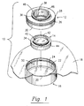
- FIG. 1 is an exploded view of the mounting ring and drape, together with the microscope objective lens housing and adapter ring housing.
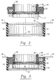
- FIG. 2 is a sectional elevational view of the adapter ring housing and microscope objective lens housing before snapping into the mounting ring housing.
- FIG. 3 is a sectional elevational view of the adapter ring housing and microscope objective lens housing mounted within the mounting ring housing.
- Throughout the following detailed description, the same reference numerals refer to the same elements in all figures.
- The universal
microscope drape assembly 10 has anadapter ring housing 12, a microscopeobjective lens housing 14, amounting ring housing 16, and a thin polymer sheet forming adrape 18 as shown in FIG. 1. - The
mounting ring housing 16 is integral withdrape 18 by a seal alongedge 20. Theinside circumference 22 of themounting ring housing 16 contains agroove 24 which is annular in shape to accommodate a protrudingring 26 from theadapter ring housing 12 as shown in FIG. 1. Theinner circumference wall 22 of the mounting ring and theouter circumference wall 28 of the adapter ring provide a close airtight fit after the protrudingring 26 is locked in place in receivinggroove 24. The microscopeobjective lens housing 14 is mounted within thesecond end 30 of theadapter ring housing 12 andthreads 32 withinadapter ring housing 12 engagethreads 34 on an outer circumference of the microscopeobjective lens housing 14.Threads 36 on an outer circumference of theadapter ring housing 12 accommodate to a set of threads within the microscope body inner circumference (not shown).Threads adapter 12 so that there is an exact fit with a particular manufacture or style of microscope to which the adapter is fitted. Theouter circumference 28 and protrudingring 26 will be the same diameter on each adapter ring so that they will accommodate themounting ring housing 16. - Referring to FIG. 2, the adapter ring housing 12 with
threads 32 on itsinner wall diameter 38 receives theouter threads 34 from a microscopeobjective lens housing 14. Amicroscope lens 40 is integral with theinterior wall 42 of the microscopeobjective lens housing 14. A bottom portion orskirt 44 of theobjective lens housing 14 is received within mounting ring housinginner circumference 22 and abuts on theplastic lens 52.Skirt 44 is below theadapter 12 when engaged to the adapter as seen in FIGS. 2 and 3 to a depth of about 1-5 centimeters. - The
adapter ring housing 12 has anupper flange 46 fitting flush against and upperannular member 48 for insertion within, the microscope body.Threads 36 on theadapter ring housing 12 engage the corresponding threads within the microscope. As shown in FIG. 3, the microscope objective lens housing 14 andadapter ring housing 12 are engaged by therespective threads objective lens housing 14 engaged receives themounting ring housing 16 by an upwards pushing of the mountingring housing 16. The depth of theinner wall 50 of the mounting ring housing is sufficient to accommodate the outer diameter ring orskirt 44 of the microscope objective lens housing 14 so that the microscope objective lens housing 14 closely abuts theplastic lens 52 mounted withingroove 54 of themounting ring housing 16. - The
mounting ring 16 can be made of a high strength plastic substance. Theadapter ring housing 12 can be manufactured from an aluminum alloy or a high strength plastic such as DELRIN®, made by E.I. duPont de Nemours & Company, Inc. - Typical threads found in various commonly used microscopes have a range of 50 to 68 threads per millimeter in Storz, St. Louis, Topcon, Moeller Wedel and Jed-Med microscopes. In Zeiss OPMI 99, Zeiss MD, Cabot, Olympus, Elmed, Inami, AusJena, and Nikon microscopes there are 36 to 63 threads per 0.75 millimeters. Codman, OMS300 & 320 and Weck microscopes use the English system of thread sizes.
- Substitution of other holding means for the
groove 24 and protrudingmember 26 can be employed to confirm a secure mounting bond between the adapter ring housing and the mounting ring housing. Themicroscope drape 18 can be any type thin polymer sheet as shown on U.S. Patent 4,561,540 and 3,528,720 which are herein incorporated by reference.
Claims (7)
- In a disposable thin polymer microscope drape assembly for maintaining a sterile envelope around an operating room microscope having a mounting ring housing integral with the drape for engagement with an objective lens housing of a microscope, the improvement comprising
an inner diameter of the mounting ring housing having a width corresponding to an outside diameter of an adapter ring housing,
a means for attaching the mounting ring housing to the adapter ring housing,
a first end of the adapter ring housing having a means for engaging a microscope body,
a second end of the adapter ring housing having a means for engaging a microscope objective lens housing, and
the mounting ring housing having a depth to enclose a lower end of the microscope objective lens housing and retain a clear plastic lens. - The microscope drape assembly according to claim 1 wherein the means for attaching the mounting ring housing to the adapter ring housing is an annular groove within an interior wall of the mounting ring housing, the interior wall groove receiving an annular protrusion on an outer wall of the adapter ring housing when the mounting ring is pushed onto the adapter ring.
- The microscope drape assembly according to claim 1 wherein the first end of the adapter ring housing has threads for engaging corresponding threads within the microscope body to provide the means for engaging the microscope body.
- The microscope drape assembly according to claim 1 wherein the second end of the adapter ring housing has threads for engaging corresponding threads on a microscope objective lens housing.
- The microscope drape assembly according to claim 1 wherein the adapter ring and mounting ring are made from a polymer.
- The microscope drape assembly according to claim 4 herein the objective lens housing has a skirt descending about 1-5 centimeters below the adapter housing when the objective lens housing is threaded to the adapter housing.
- In a disposable microscope drape assembly for maintaining a sterile envelope around an operating room microscope having a mounting ring housing integral with the drape for engagement with an objective lens housing of a microscope, the improvement comprising
an inner wall diameter of the mounting ring housing corresponding to an outside wall diameter of an adapter ring housing,
a first end of the adapter ring having threads compatibly engaged to threads within the body of the microscope,
a second end of the adapter ring housing having threads compatibly engaged to threads in a top end of a microscope objective lens housing, the objective lens housing having a descending annular skirt at a bottom end,
the mounting ring having a depth sufficient to enclose the microscope objective lens housing skirt and having an annular groove on the inner wall to receive an annular protruding member on the outer wall of the adapter ring housing so that the assembly is locked in place over the microscope but can be disassembled for disposal of the mounting ring and drape.
Applications Claiming Priority (2)
| Application Number | Priority Date | Filing Date | Title |
|---|---|---|---|
| US958497 | 1992-10-08 | ||
| US07/958,497 US5311358A (en) | 1992-10-08 | 1992-10-08 | Universal microscope drape |
Publications (2)
| Publication Number | Publication Date |
|---|---|
| EP0591936A1 true EP0591936A1 (en) | 1994-04-13 |
| EP0591936B1 EP0591936B1 (en) | 1996-07-24 |
Family
ID=25500998
Family Applications (1)
| Application Number | Title | Priority Date | Filing Date |
|---|---|---|---|
| EP93116113A Expired - Lifetime EP0591936B1 (en) | 1992-10-08 | 1993-10-06 | Universal microscope drape |
Country Status (10)
| Country | Link |
|---|---|
| US (1) | US5311358A (en) |
| EP (1) | EP0591936B1 (en) |
| JP (1) | JPH0723979A (en) |
| AT (1) | ATE140802T1 (en) |
| AU (1) | AU653296B2 (en) |
| CA (1) | CA2107700C (en) |
| DE (1) | DE69303791T2 (en) |
| NO (1) | NO308876B1 (en) |
| NZ (1) | NZ248876A (en) |
| ZA (1) | ZA937370B (en) |
Cited By (4)
| Publication number | Priority date | Publication date | Assignee | Title |
|---|---|---|---|---|
| WO1996017558A1 (en) * | 1994-12-07 | 1996-06-13 | Adair Edwin Lloyd | Sterile surgical coupler and drape |
| WO1997032534A1 (en) * | 1994-10-03 | 1997-09-12 | Adair Edwin Lloyd | Sterile surgical coupler and drape |
| EP3643267A1 (en) * | 2014-07-01 | 2020-04-29 | Spier, Laurence | Surgical robotic instrument shield |
| IT202000002536A1 (en) | 2020-02-10 | 2021-08-10 | Medical Microinstruments Spa | STERILE ADAPTER FOR A ROBOTIC SURGERY SYSTEM, ASSEMBLY, SYSTEM AND METHOD |
Families Citing this family (46)
| Publication number | Priority date | Publication date | Assignee | Title |
|---|---|---|---|---|
| US5682264A (en) * | 1993-03-01 | 1997-10-28 | Microtek Medical, Inc. | Universal microscope drape |
| US5608574A (en) * | 1993-06-18 | 1997-03-04 | Carl Zeiss, Inc. | Surgical drape for an operation microscope |
| US5467223A (en) * | 1993-12-16 | 1995-11-14 | Xomed-Treace Inc. | Drape adapter |
| US5455711A (en) * | 1994-03-08 | 1995-10-03 | Itt Corporation | Magnification lens coupling device for a night vision assembly |
| US5898522A (en) * | 1995-10-06 | 1999-04-27 | Herpst; Robert D. | Protective window assembly and method of using the same for a laser beam generating apparatus |
| AUPO478397A0 (en) * | 1997-01-31 | 1997-02-20 | Fairmont Medical Products Pty Ltd | Endoscopic drape |
| US5876328A (en) * | 1997-04-23 | 1999-03-02 | Endolap, Inc. | Surgical camera drape assembly and method |
| ES2210748T3 (en) | 1997-05-05 | 2004-07-01 | Global Surgical Corporation | CURTAIN FOR A SURGICAL MICROSCOPE WITH ANTIHAL WINDOW. |
| US5853363A (en) * | 1997-07-28 | 1998-12-29 | Deka Medical, Inc. | Surgical microscope operating drape and methods of operation and manufacture thereof |
| US6116741A (en) * | 1998-03-13 | 2000-09-12 | Deka Medical, Incorporated | Surgical microscope operating drape and methods of operation and manufacture thereof |
| US6024454A (en) * | 1998-12-04 | 2000-02-15 | Ph Medical, Inc. | Microscope drape system |
| EP1161702B1 (en) * | 1999-02-17 | 2014-07-23 | Lucid, Inc. | Tissue specimen holder |
| US6683724B2 (en) * | 2002-06-13 | 2004-01-27 | Eastman Kodak Company | Solid immersion lens array and methods for producing a solid immersion lens array |
| DE10250811A1 (en) * | 2002-08-16 | 2004-03-04 | Stuemed Gmbh | Microscope cover with lens ring II |
| US6902278B2 (en) * | 2003-03-24 | 2005-06-07 | Andrew J. Bala | Surgical microscope drape assembly |
| US7234824B2 (en) * | 2003-09-22 | 2007-06-26 | Langley Nicholas M | Glare-elimination device for surgical microscopes |
| US6876503B1 (en) | 2003-10-28 | 2005-04-05 | Contour Fabricators, Inc. | Microscope drape lens protective cover assembly |
| US20050094269A1 (en) * | 2003-10-31 | 2005-05-05 | Moses Gary L. | Microscope drape coupling system and method |
| JP2006145771A (en) * | 2004-11-18 | 2006-06-08 | Olympus Corp | Microscope objective, microscope and electric insulating member |
| US20080166646A1 (en) * | 2006-10-31 | 2008-07-10 | Xerox Corporation | Toner for reduced photoreceptor wear rate |
| US20080144178A1 (en) * | 2006-12-13 | 2008-06-19 | Microtek Medical, Inc. | Microscope drape lens cover system and assembly method |
| JP4321605B2 (en) * | 2007-02-26 | 2009-08-26 | ソニー株式会社 | Lens adapter and imaging device |
| US20100238551A1 (en) * | 2009-03-19 | 2010-09-23 | Hubbs Charles M | Surgical microscope drape lens for reducing glare |
| US8506094B2 (en) | 2009-12-29 | 2013-08-13 | Medline Industries, Inc. | Medical lens assemblies and sterile drapes with a lens assembly |
| EP2640303B1 (en) * | 2010-11-19 | 2017-01-04 | Leopold Lackner | Cover for an ultrasonic head |
| US9706868B2 (en) | 2011-02-15 | 2017-07-18 | Brainlab Ag | Drape-clamping reference array connector |
| US8279544B1 (en) | 2011-03-18 | 2012-10-02 | Premier Systems USA, Inc | Selectively attachable and removable lenses for communication devices |
| CN104254767B (en) | 2012-02-26 | 2016-10-26 | 克力博成像诊断股份有限公司 | For optical section microscopical tissue samples workbench |
| DE102012016347B4 (en) | 2012-08-16 | 2022-09-08 | Carl Zeiss Microscopy Gmbh | Microscope for SPIM microscopy |
| WO2014043266A1 (en) | 2012-09-12 | 2014-03-20 | Premier Systems Usa, Inc. | Removable optical devices for mobile electronic devices |
| US9294660B2 (en) | 2013-03-13 | 2016-03-22 | Olloclip, Llc | Removable lenses for mobile electronic devices |
| US9661200B2 (en) | 2013-08-07 | 2017-05-23 | Olloclip, Llc | Auxiliary optical components for mobile devices |
| WO2015048143A1 (en) | 2013-09-26 | 2015-04-02 | Olloclip, Llc | Selectively attachable and removable optical systems for mobile devices |
| USD754228S1 (en) | 2014-02-19 | 2016-04-19 | olioclip, LLC | Optical component |
| US10088738B2 (en) | 2014-04-11 | 2018-10-02 | Portero Holdings, Llc | Auxiliary optical devices |
| USD761896S1 (en) | 2014-04-11 | 2016-07-19 | Olloclip, Llc | Optical component |
| US9454066B2 (en) | 2014-06-19 | 2016-09-27 | Olloclip, Llc | Auxiliary optical components for mobile devices |
| USD763340S1 (en) | 2014-10-02 | 2016-08-09 | Olloclip, Llc | Optical component |
| JP1573246S (en) | 2015-12-11 | 2017-04-03 | ||
| JP1572210S (en) * | 2016-07-28 | 2020-03-02 | ||
| JP1571875S (en) * | 2016-07-28 | 2020-03-02 | ||
| JP1572209S (en) * | 2016-07-28 | 2020-03-02 | ||
| USD877226S1 (en) * | 2017-04-28 | 2020-03-03 | Ecolab Usa Inc. | Optical lens housing |
| US11547281B2 (en) * | 2018-02-15 | 2023-01-10 | Covidien Lp | Sheath assembly for a rigid endoscope |
| DE102018107357A1 (en) * | 2018-03-28 | 2019-10-02 | Aesculap Ag | Mounting adapter for attaching a sterile cover to a microscope, a microscope for use with such an adapter and system with deratigen microscope and such an adapter |
| WO2023147702A1 (en) * | 2022-02-07 | 2023-08-10 | Mazor Robotics Ltd. | Housing for a sterile cover and a filter |
Citations (2)
| Publication number | Priority date | Publication date | Assignee | Title |
|---|---|---|---|---|
| US4266663A (en) * | 1979-11-13 | 1981-05-12 | Carl Zeiss, Inc. | Surgical drape for an operating microscope |
| US4385812A (en) * | 1981-02-02 | 1983-05-31 | Surgikos, Inc. | Objective lens cover assembly for an operating microscope |
Family Cites Families (10)
| Publication number | Priority date | Publication date | Assignee | Title |
|---|---|---|---|---|
| US3133140A (en) * | 1960-09-23 | 1964-05-12 | Winchell Paul | Lens cover |
| US3528720A (en) * | 1968-12-18 | 1970-09-15 | Richards Mfg Co | Operating microscope envelope means |
| US3698791A (en) * | 1971-04-19 | 1972-10-17 | Xerox Corp | Drape for operating microscope |
| US3796477A (en) * | 1972-09-25 | 1974-03-12 | Xomox Corp | Lens housing and lens cover for objective lens ring of an operating microscope |
| US4564270A (en) * | 1983-07-05 | 1986-01-14 | Surgikos, Inc. | Objective lens cover for an operating microscope |
| US4561540A (en) * | 1983-12-14 | 1985-12-31 | Xomed Inc. | Microscope drape |
| US4807594A (en) * | 1988-01-15 | 1989-02-28 | Medical Concepts, Incorporated | Adapter assembly for endoscopic video camera |
| US4799779A (en) * | 1988-03-22 | 1989-01-24 | Mesmer Jeffrey C | Microscope drape |
| JPH0358609U (en) * | 1989-10-12 | 1991-06-07 | ||
| JPH0492658A (en) * | 1990-08-07 | 1992-03-25 | Kataoka Shoji Kk | Removable prosthesis and implant for removable prosthesis |
-
1992
- 1992-10-08 US US07/958,497 patent/US5311358A/en not_active Expired - Fee Related
-
1993
- 1993-10-05 CA CA002107700A patent/CA2107700C/en not_active Expired - Lifetime
- 1993-10-05 ZA ZA937370A patent/ZA937370B/en unknown
- 1993-10-06 AT AT93116113T patent/ATE140802T1/en not_active IP Right Cessation
- 1993-10-06 EP EP93116113A patent/EP0591936B1/en not_active Expired - Lifetime
- 1993-10-06 DE DE69303791T patent/DE69303791T2/en not_active Expired - Lifetime
- 1993-10-06 NZ NZ248876A patent/NZ248876A/en not_active IP Right Cessation
- 1993-10-07 NO NO933589A patent/NO308876B1/en not_active IP Right Cessation
- 1993-10-07 JP JP5276067A patent/JPH0723979A/en active Pending
- 1993-10-07 AU AU48884/93A patent/AU653296B2/en not_active Expired
Patent Citations (2)
| Publication number | Priority date | Publication date | Assignee | Title |
|---|---|---|---|---|
| US4266663A (en) * | 1979-11-13 | 1981-05-12 | Carl Zeiss, Inc. | Surgical drape for an operating microscope |
| US4385812A (en) * | 1981-02-02 | 1983-05-31 | Surgikos, Inc. | Objective lens cover assembly for an operating microscope |
Cited By (6)
| Publication number | Priority date | Publication date | Assignee | Title |
|---|---|---|---|---|
| WO1997032534A1 (en) * | 1994-10-03 | 1997-09-12 | Adair Edwin Lloyd | Sterile surgical coupler and drape |
| WO1996017558A1 (en) * | 1994-12-07 | 1996-06-13 | Adair Edwin Lloyd | Sterile surgical coupler and drape |
| EP3643267A1 (en) * | 2014-07-01 | 2020-04-29 | Spier, Laurence | Surgical robotic instrument shield |
| US11766358B2 (en) * | 2014-07-01 | 2023-09-26 | Laurence Spier | Surgical robotic instrument shield |
| IT202000002536A1 (en) | 2020-02-10 | 2021-08-10 | Medical Microinstruments Spa | STERILE ADAPTER FOR A ROBOTIC SURGERY SYSTEM, ASSEMBLY, SYSTEM AND METHOD |
| WO2021161184A1 (en) | 2020-02-10 | 2021-08-19 | Medical Microinstruments S.p.A. | Sterile adapter for a robotic surgery system, assembly, system and method |
Also Published As
| Publication number | Publication date |
|---|---|
| EP0591936B1 (en) | 1996-07-24 |
| JPH0723979A (en) | 1995-01-27 |
| NZ248876A (en) | 1996-02-27 |
| NO933589D0 (en) | 1993-10-07 |
| CA2107700A1 (en) | 1994-04-09 |
| AU653296B2 (en) | 1994-09-22 |
| NO308876B1 (en) | 2000-11-06 |
| DE69303791D1 (en) | 1996-08-29 |
| ATE140802T1 (en) | 1996-08-15 |
| ZA937370B (en) | 1994-04-29 |
| AU4888493A (en) | 1994-04-28 |
| CA2107700C (en) | 1995-10-10 |
| DE69303791T2 (en) | 1997-01-30 |
| US5311358A (en) | 1994-05-10 |
| NO933589L (en) | 1994-04-11 |
Similar Documents
| Publication | Publication Date | Title |
|---|---|---|
| US5311358A (en) | Universal microscope drape | |
| EP3029506B1 (en) | Medical lens assemblies and sterile drapes with a lens assembly | |
| EP0941706B1 (en) | Surgical microscope operating drape and methods of operation and manufacture thereof | |
| US5682264A (en) | Universal microscope drape | |
| US5792045A (en) | Sterile surgical coupler and drape | |
| EP2101673B1 (en) | Microscope drape lens cover system and assembly method | |
| US6024454A (en) | Microscope drape system | |
| EP0721600B1 (en) | Drape adapter | |
| EP0955014A1 (en) | Sterile surgical coupler and drape | |
| US5853363A (en) | Surgical microscope operating drape and methods of operation and manufacture thereof | |
| US20050094269A1 (en) | Microscope drape coupling system and method | |
| US5155624A (en) | Lens housing for sterile cover of an operating microscope | |
| EP3491993A1 (en) | Coupler for endoscopic camera | |
| US5604955A (en) | Surgical lighting fixture cover | |
| EP0923350B1 (en) | Sterile surgical coupler and drape | |
| CN219050016U (en) | Sealing element and ureteral sheath |
Legal Events
| Date | Code | Title | Description |
|---|---|---|---|
| PUAI | Public reference made under article 153(3) epc to a published international application that has entered the european phase |
Free format text: ORIGINAL CODE: 0009012 |
|
| AK | Designated contracting states |
Kind code of ref document: A1 Designated state(s): AT BE CH DE DK ES FR GB GR IE IT LI LU NL PT SE |
|
| 17P | Request for examination filed |
Effective date: 19940509 |
|
| GRAG | Despatch of communication of intention to grant |
Free format text: ORIGINAL CODE: EPIDOS AGRA |
|
| 17Q | First examination report despatched |
Effective date: 19951213 |
|
| GRAH | Despatch of communication of intention to grant a patent |
Free format text: ORIGINAL CODE: EPIDOS IGRA |
|
| GRAH | Despatch of communication of intention to grant a patent |
Free format text: ORIGINAL CODE: EPIDOS IGRA |
|
| GRAA | (expected) grant |
Free format text: ORIGINAL CODE: 0009210 |
|
| AK | Designated contracting states |
Kind code of ref document: B1 Designated state(s): AT BE CH DE DK ES FR GB GR IE IT LI LU NL PT SE |
|
| PG25 | Lapsed in a contracting state [announced via postgrant information from national office to epo] |
Ref country code: NL Free format text: LAPSE BECAUSE OF FAILURE TO SUBMIT A TRANSLATION OF THE DESCRIPTION OR TO PAY THE FEE WITHIN THE PRESCRIBED TIME-LIMIT Effective date: 19960724 Ref country code: LI Effective date: 19960724 Ref country code: GR Free format text: LAPSE BECAUSE OF FAILURE TO SUBMIT A TRANSLATION OF THE DESCRIPTION OR TO PAY THE FEE WITHIN THE PRESCRIBED TIME-LIMIT Effective date: 19960724 Ref country code: ES Free format text: THE PATENT HAS BEEN ANNULLED BY A DECISION OF A NATIONAL AUTHORITY Effective date: 19960724 Ref country code: DK Effective date: 19960724 Ref country code: CH Effective date: 19960724 Ref country code: BE Effective date: 19960724 Ref country code: AT Effective date: 19960724 |
|
| REF | Corresponds to: |
Ref document number: 140802 Country of ref document: AT Date of ref document: 19960815 Kind code of ref document: T |
|
| REF | Corresponds to: |
Ref document number: 69303791 Country of ref document: DE Date of ref document: 19960829 |
|
| ET | Fr: translation filed | ||
| REG | Reference to a national code |
Ref country code: IE Ref legal event code: FG4D Free format text: 69226 |
|
| PG25 | Lapsed in a contracting state [announced via postgrant information from national office to epo] |
Ref country code: IE Free format text: LAPSE BECAUSE OF NON-PAYMENT OF DUE FEES Effective date: 19961006 |
|
| ITF | It: translation for a ep patent filed |
Owner name: STUDIO ING. ALFREDO RAIMONDI |
|
| PG25 | Lapsed in a contracting state [announced via postgrant information from national office to epo] |
Ref country code: SE Effective date: 19961024 Ref country code: PT Effective date: 19961024 |
|
| PG25 | Lapsed in a contracting state [announced via postgrant information from national office to epo] |
Ref country code: LU Free format text: LAPSE BECAUSE OF NON-PAYMENT OF DUE FEES Effective date: 19961031 |
|
| NLV1 | Nl: lapsed or annulled due to failure to fulfill the requirements of art. 29p and 29m of the patents act | ||
| REG | Reference to a national code |
Ref country code: CH Ref legal event code: PL |
|
| PLBE | No opposition filed within time limit |
Free format text: ORIGINAL CODE: 0009261 |
|
| STAA | Information on the status of an ep patent application or granted ep patent |
Free format text: STATUS: NO OPPOSITION FILED WITHIN TIME LIMIT |
|
| 26N | No opposition filed | ||
| REG | Reference to a national code |
Ref country code: GB Ref legal event code: IF02 |
|
| PGFP | Annual fee paid to national office [announced via postgrant information from national office to epo] |
Ref country code: GB Payment date: 20120925 Year of fee payment: 20 |
|
| PGFP | Annual fee paid to national office [announced via postgrant information from national office to epo] |
Ref country code: DE Payment date: 20121031 Year of fee payment: 20 Ref country code: FR Payment date: 20121010 Year of fee payment: 20 |
|
| PGFP | Annual fee paid to national office [announced via postgrant information from national office to epo] |
Ref country code: IT Payment date: 20121018 Year of fee payment: 20 |
|
| REG | Reference to a national code |
Ref country code: DE Ref legal event code: R071 Ref document number: 69303791 Country of ref document: DE |
|
| REG | Reference to a national code |
Ref country code: DE Ref legal event code: R071 Ref document number: 69303791 Country of ref document: DE |
|
| REG | Reference to a national code |
Ref country code: GB Ref legal event code: PE20 Expiry date: 20131005 |
|
| PG25 | Lapsed in a contracting state [announced via postgrant information from national office to epo] |
Ref country code: GB Free format text: LAPSE BECAUSE OF EXPIRATION OF PROTECTION Effective date: 20131005 Ref country code: DE Free format text: LAPSE BECAUSE OF EXPIRATION OF PROTECTION Effective date: 20131008 |