EP0590774B1 - Apparatus for producing an oriented single file of articles - Google Patents
Apparatus for producing an oriented single file of articles Download PDFInfo
- Publication number
- EP0590774B1 EP0590774B1 EP93306436A EP93306436A EP0590774B1 EP 0590774 B1 EP0590774 B1 EP 0590774B1 EP 93306436 A EP93306436 A EP 93306436A EP 93306436 A EP93306436 A EP 93306436A EP 0590774 B1 EP0590774 B1 EP 0590774B1
- Authority
- EP
- European Patent Office
- Prior art keywords
- articles
- conveyor
- pockets
- edge
- support surface
- Prior art date
- Legal status (The legal status is an assumption and is not a legal conclusion. Google has not performed a legal analysis and makes no representation as to the accuracy of the status listed.)
- Expired - Lifetime
Links
- 238000000034 method Methods 0.000 claims abstract description 9
- 230000005484 gravity Effects 0.000 claims description 10
- 238000012546 transfer Methods 0.000 claims description 6
- 239000012530 fluid Substances 0.000 claims description 5
- 238000011144 upstream manufacturing Methods 0.000 claims 2
- 238000004140 cleaning Methods 0.000 description 5
- 239000002775 capsule Substances 0.000 description 3
- 238000010276 construction Methods 0.000 description 3
- 241000510097 Megalonaias nervosa Species 0.000 description 2
- 239000000428 dust Substances 0.000 description 2
- 239000002245 particle Substances 0.000 description 2
- 238000012797 qualification Methods 0.000 description 2
- 230000003134 recirculating effect Effects 0.000 description 2
- 238000004064 recycling Methods 0.000 description 2
- 239000000853 adhesive Substances 0.000 description 1
- 230000001070 adhesive effect Effects 0.000 description 1
- 239000000835 fiber Substances 0.000 description 1
- 239000000463 material Substances 0.000 description 1
- 238000012986 modification Methods 0.000 description 1
- 230000004048 modification Effects 0.000 description 1
- 238000012545 processing Methods 0.000 description 1
- 230000000717 retained effect Effects 0.000 description 1
- 230000000153 supplemental effect Effects 0.000 description 1
Images





Classifications
-
- B—PERFORMING OPERATIONS; TRANSPORTING
- B65—CONVEYING; PACKING; STORING; HANDLING THIN OR FILAMENTARY MATERIAL
- B65G—TRANSPORT OR STORAGE DEVICES, e.g. CONVEYORS FOR LOADING OR TIPPING, SHOP CONVEYOR SYSTEMS OR PNEUMATIC TUBE CONVEYORS
- B65G47/00—Article or material-handling devices associated with conveyors; Methods employing such devices
- B65G47/02—Devices for feeding articles or materials to conveyors
- B65G47/04—Devices for feeding articles or materials to conveyors for feeding articles
- B65G47/12—Devices for feeding articles or materials to conveyors for feeding articles from disorderly-arranged article piles or from loose assemblages of articles
- B65G47/14—Devices for feeding articles or materials to conveyors for feeding articles from disorderly-arranged article piles or from loose assemblages of articles arranging or orientating the articles by mechanical or pneumatic means during feeding
- B65G47/1407—Devices for feeding articles or materials to conveyors for feeding articles from disorderly-arranged article piles or from loose assemblages of articles arranging or orientating the articles by mechanical or pneumatic means during feeding the articles being fed from a container, e.g. a bowl
- B65G47/1442—Devices for feeding articles or materials to conveyors for feeding articles from disorderly-arranged article piles or from loose assemblages of articles arranging or orientating the articles by mechanical or pneumatic means during feeding the articles being fed from a container, e.g. a bowl by means of movement of the bottom or a part of the wall of the container
- B65G47/1471—Movement in one direction, substantially outwards
-
- B—PERFORMING OPERATIONS; TRANSPORTING
- B65—CONVEYING; PACKING; STORING; HANDLING THIN OR FILAMENTARY MATERIAL
- B65G—TRANSPORT OR STORAGE DEVICES, e.g. CONVEYORS FOR LOADING OR TIPPING, SHOP CONVEYOR SYSTEMS OR PNEUMATIC TUBE CONVEYORS
- B65G47/00—Article or material-handling devices associated with conveyors; Methods employing such devices
- B65G47/52—Devices for transferring articles or materials between conveyors i.e. discharging or feeding devices
- B65G47/525—Devices for transferring articles or materials between conveyors i.e. discharging or feeding devices using fluid jets
-
- B—PERFORMING OPERATIONS; TRANSPORTING
- B65—CONVEYING; PACKING; STORING; HANDLING THIN OR FILAMENTARY MATERIAL
- B65G—TRANSPORT OR STORAGE DEVICES, e.g. CONVEYORS FOR LOADING OR TIPPING, SHOP CONVEYOR SYSTEMS OR PNEUMATIC TUBE CONVEYORS
- B65G47/00—Article or material-handling devices associated with conveyors; Methods employing such devices
- B65G47/52—Devices for transferring articles or materials between conveyors i.e. discharging or feeding devices
- B65G47/68—Devices for transferring articles or materials between conveyors i.e. discharging or feeding devices adapted to receive articles arriving in one layer from one conveyor lane and to transfer them in individual layers to more than one conveyor lane or to one broader conveyor lane, or vice versa, e.g. combining the flows of articles conveyed by more than one conveyor
- B65G47/682—Devices for transferring articles or materials between conveyors i.e. discharging or feeding devices adapted to receive articles arriving in one layer from one conveyor lane and to transfer them in individual layers to more than one conveyor lane or to one broader conveyor lane, or vice versa, e.g. combining the flows of articles conveyed by more than one conveyor from a single conveyor lane consisting of one conveyor or several adjacent conveyors
- B65G47/684—Devices for transferring articles or materials between conveyors i.e. discharging or feeding devices adapted to receive articles arriving in one layer from one conveyor lane and to transfer them in individual layers to more than one conveyor lane or to one broader conveyor lane, or vice versa, e.g. combining the flows of articles conveyed by more than one conveyor from a single conveyor lane consisting of one conveyor or several adjacent conveyors with recirculation of articles forming a buffer
Definitions
- the invention relates to a system for producing a single file of oriented articles from a jumbled bulk supply. More specifically, the invention relates to a linear apparatus and method for feeding a single file of oriented bottles from a bulk hopper to downstream stations.
- U.S. Patent No. 2,771,191 discloses a device which supports capsules on a spaced apart pair of fulcrum blades. One or the other blade is moved transversely away from the capsule, depending upon which end is sensed as the cap end, and the capsule is permitted to fall. This device disadvantageously requires a fairly large number of interrelated moving parts.
- FR-A-2,536,050 discloses a device according to the precharacterizing clause of claim 1 which generates a single file of oriented articles from three infeed files of articles.
- the infeed files are formed by successive transverse rows of three articles aligned end-to-end in transversely extending pockets in a conveyor.
- the device relies on the supposition that, if three articles are randomly deposited in each pocket, at least one of these articles will "probably" be oriented in the required direction.
- the device rejects from each row all but one article which has the required orientation. This device is relatively inefficient in that, at best, at least two articles from each row are rejected and have to be recycled. At worst, for rows containing no articles having the required orientation, all three articles are rejected and have to be recycled.
- U.S. Patent No. 3,392,815 discloses a swivel hook which enters open ends of bottles to transfer them to the far side of a funnel but can not enter bottle bottoms which fall into the near side of the funnel.
- the invention is directed to an apparatus for producing an oriented single file of articles, of the general type disclosed in FR-A-2,536,050, comprising:
- the conveyor includes spaced-apart vanes forming/separating the pockets.
- the conveyor includes a plurality of transverse grooves and means for releasably locking pocket-forming vanes in the grooves.
- the lateral support surface is preferably a deadplate including an article stopping wall.
- a direction-determining device is provided, which is preferably a wiper which only one end of the articles can fit beneath.
- a sensor/switch is provided for sensing an article extending beneath the wiper and for switching the article-moving means or device ON and OFF as necessary.
- the article-moving device is preferably a fluid jet, and the sensor/switch is preferably an optical-type sensor.
- a guide is used to cam articles aligned with an end which does not fit beneath the wiper, toward and over an edge of the conveyor.
- the linear feeder embodying the invention is usable with a variety of different article types and shapes, and qualifies the articles by the size and/or shape of an end of the article.
- the pockets are formed by vanes which convey the articles along the drop zone, the vanes including slits for introducing an article guide.
- the pockets or vanes may be relatively quickly and easily changed or moved to accommodate different size articles.
- FIG. 1 is a front isometric view of a linear feeder 20 embodying the invention.
- FIGS. 2-10 and 6A are enlarged partial views which illustrate specific components and operation of feeder 20.
- Linear feeder 20 is generally comprised of a prefeeder 22, a preorientation chute 23, a singulation station 24, an orientation station 26, a cleaning station 28 (see FIG. 9) and an output conveyor 30, mounted together on a frame 21.
- Prefeeder 22 includes a prefeed conveyor 32 for metering articles 34 such as plastic bottles from a supply hopper 36, mounted adjacent the prefeed conveyor, to preorientation chute 23.
- Supply hopper 36 includes downwardly and inwardly sloping side walls 38, a plurality of rigid grates 40 and a plurality of flexible grates 42 mounted across lower opening of hopper 36 adjacent the top surface of prefeed conveyor 32. Sloping side walls 38 and flexible grates 42 are designed to meter articles 34 in a smooth, steady fashion from hopper 36 to conveyor 32 and into downwardly sloping preorientation chute 23 which is preferably, but need not be, aligned substantially parallel to the prefeed conveyor, and which has a "washboard configuration" as illustrated in the cross-sectional view of FIG. 2.
- chute 23 is divided into a plurality of longitudinal lanes 44 having sloping walls 46.
- Walls 46 meet in a plurality of peaks 45 and valleys 47 which preferably follow concentric arcs R1 and R2 designed to urge articles toward the center of chute 23. Peaks 45 are preferably radiused to prevent them from damaging tumbling articles.
- the provision of longitudinal lanes 44 tends to naturally rotated articles 34 with their axes A (see FIG. 3 also) arranged substantially longitudinally, i.e., substantially in the downstream direction indicated by the arrow 60, with respect to chute 23.
- the provision of sloping walls 46 in downwardly sloping chute 23 further tends to arrange articles 34 lying on their sides within lanes 44.
- conveyor 52 is preferably substantially horizontal to facilitate pocket loading.
- Conveyor 52 is aligned substantially perpendicular to chute 23, and the downstream direction 60 changes accordingly so that articles leaving lanes 44 can slide directly into the pockets which are transversely arranged on conveyor 52.
- conveyor 52 is a vaned conveyor provided with a plurality of spaced-apart vanes, blades, paddles or the like 56 which form and separate pockets 50.
- Pockets 50 of conveyor 52 are preferably sized to hold two or more articles 34 lying end to end on their sides.
- chute 23 and loading zone 54 will very likely include a few articles 34a which tumble down chute 23 or conveyor 52.
- loading zone 54 includes side walls (not shown) which prevent articles 34a from cascading off conveyor 52 and permit them to attempt to fill empty pocket spaces.
- Loading zone 54 preferably also includes a sensor (not shown) for slowing or stopping prefeed conveyor 32 most preferably by a controller (also not shown) to slow or stop delivery of articles 34 to loading zone 54. It has been determined that maximum loading efficiency is attained when the speed of prefeed conveyor 32 is adjusted to supply a relatively steady stream of articles 34 to loading zone 54 which prevents an excessive buildup of articles 34a necessitating frequent starting and stopping of the prefeed conveyor.
- vaned conveyor 52 Downstream of, i.e., in the direction of arrows 60 from loading zone 54, vaned conveyor 52 slopes upwardly toward singulation station 24.
- the angle alpha of inclination of conveyor 52 is preferably selected together with the height v to which vanes 56 extend above surface 53 of vaned conveyor 52 such that articles 34b loaded in pockets 50 in a standing as opposed to a lying position will tend to fall out of pockets 50 by force of gravity as indicated by arrow 62.
- vaned conveyor 52 is level and does not slope, or where supplemental forces are required to remove standing articles from pockets
- air jets, wipers or other means may be provided to tip the articles out of the pockets, and that sensors may also be provided to identify such standing articles.
- Height v of vanes 56 is less than a distance d between conveyor surface 53 and the highest point on the lowest end 63 of articles 34 as they lie on their sides within pockets 50. Referring to FIG. 4, this is necessary so that wiper or guide rail 64 mounted above conveyor 52 and above vanes 56 can shift or cam articles 34 regardless of whether lower ends 63 or higher ends 65 are abutting the guide.
- Guide 64 shifts articles transversely across conveyor surface 53 along pockets 50 toward edge 66 of conveyor 52 as vanes 56 carry the articles downstream.
- Guide 64 also functions to remove all but one article 34 from every pocket which is loaded with more than one article.
- pockets 50 are preferably sized to accommodate two or more articles 34 aligned end to end across pocket conveyor 52. This is done to improve the chances that each pocket 50 will include at least one article in order to maintain relatively constant machine throughput. It is understood that pockets occasionally may not be loaded with any articles and that unacceptable numbers of empty pockets may be remedied by increasing the speed of prefeed conveyor 32.
- Guide 64 is mounted to conveyor frame 21 with brackets 68. Downstream end 70 of guide 64 is mounted a distance equal to about one article length l away from edge 66 of conveyor 52. As guide 64 shifts articles 34c in contact therewith toward conveyor edge 66, these articles shift other articles 34d in the pocket off conveyor 52. As indicated by arrow 72, articles 34d shifted off conveyor 52 fall by gravity into a recirculation or recycling chute 74. Articles 34c remain on conveyor 52 and form a single file 75 of articles lying along conveyor edge 66.
- recycling chute 74 returns articles to preorientation chute 23, loading zone 54 and/or bulk storage hopper 36. It is understood that the number of articles returned by chute 74 will affect the speed at which prefeed conveyor 32 meters articles into the loading zone for maximum loading efficiency.
- single file 75 of articles is conveyed further downstream to orientation station 26.
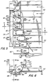
- FIGS. 5 and 6 depict operation of station 26 to orient articles 34e in input single file 75 having their heavier ends 80 initially nearest conveyor edge 66.
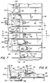
- FIGS. 7 and 8 depict operation of station 26 to orient articles 34f in input single file 75 having their lighter ends 82 initially nearest conveyor edge 66. It is understood that, in operation, single file 75 will include articles aligned in both directions, i.e., some with their lighter and some with their heavier ends initially nearer conveyor edge 66.
- Article 34e having their heavier ends 80 initially nearer conveyor edge 66 are cammed or shifted by wiper or guide 83 over conveyor edge 66 such that heavier ends 80 will fall by gravity into a drop zone 84 and onto support surface 86.
- Surface 86 may comprise a conveyor surface but is preferably a stationary surface over which articles are moved by vane portions 56' which transversely extend beyond conveyor edge 66.
- articles 34f having their lighter ends 82 initially nearer conveyor edge 66 are transversely moved off conveyor 52 across a deadplate 88 and onto a shelf or deadplate portion 90 by a fluid jet 92 or other means such as a mechanical wiper.
- Conveyor surface 53, deadplate 88 and shelf are substantially all in planar alignment for smooth article transfer.
- Vane portions 56' move articles 34f along deadplate 88 and deadplate portion 90.
- vane portions 56' include slits 106 for receiving and passing over deadplate 88. It is understood that conveyors may be used instead of these deadplates, with or without vane portions 56'. All that is essential is transferring articles 34f to a support surface on the opposite side of drop zone 84 from conveyor edge 66.
- Shelf 90 is laterally spaced from conveyor edge 66 and includes an article supporting surface 94 and an article stopping wall 96 which may include means for temporarily retaining transferred articles to prevent them from bouncing.
- the line pressure in fluid jet 92 or the angle or force of a mechanical wiper can be adjusted substantially to prevent articles from bouncing back.
- the width w of supporting surface 94 of shelf 90 is sufficiently small such that heavier ends 80 of the articles will fall by gravity into drop zone 84 and onto support surface 86.
- air jet 92 In operation to orient a random input of articles 34e, 34f, each with their heavier ends 80 facing down on support surface 86, it is necessary to selectively control operation of air jet 92 or other article moving means. Whether air jet 92 needs to be ON to move an article to shelf 90 or OFF to allow an article to pass downstream to conveyor edge 66 depends upon the direction in which the article is aligned within pocket 50, i.e., whether the lighter or heavier end of the article is initially nearer conveyor edge 66. Determining the direction in which articles are lying within the pockets is called “qualification" and must be completed for each article arriving in single file 75 at orientation station 26.
- Sensor/switch 101 may be provided as electro-optical or mechanical, however, electro-optical is preferred and fiber optic is most preferred due to their reliability and remote source.
- a controller (not shown) may be connected between sensor 101 and air jet 92 for switching the air jet ON or OFF according to logic which may be wired or programmed into the controller.
- a lower edge 102 of wiper 100 is mounted above conveyor surface 53 a very specific height which is greater than distance d (between conveyor surface 53 and the highest point on the lowest end 63 of articles) and less than distance D (between conveyor surface 53 and the highest point on the highest end 65 of articles)(see FIGS. 3 and 8). This ensures that lower ends 63 of articles can always fit beneath wiper 100 and that higher ends 65 of articles in single file 75 can not ever fit beneath wiper 100.
- ends 63 of articles aligned as 34f will pass under wiper 100 and be sensed by sensor 101 which momentarily turns air jet 92 on to move the article to shelf 90. Ends 65 of articles aligned as 34e will not extend under wiper 100 and thus not trip sensor 101 or turn air jet 92 ON and thus these articles are passed downstream. It is understood that different articles may have a different correlation of size and weight at their ends and thus may have a different switching scheme. For example, it may be necessary or desirable to turn air jet 92 momentarily OFF instead of momentarily ON.
- Singulation and orientation of articles is accomplished according to a method including the steps of introducing articles into pockets on conveyor 52, eliminating all but a single article from each pocket 50, determining whether articles are lying in a first direction (34f) or a second direction (34e), moving articles 34f to support surface 94, shifting articles 34e toward conveyor edge 66, and advancing the articles downstream with vane portions 56' whereby they fall by gravity into drop zone 84.
- At least guide 83, guide 100, sensor 101 and air jet 102 of orientation station 26 are adjustably mounted to a tooling frame 97 suspended above conveyor 52.
- vane portions 56' which slide heavier ends 80 of the articles over drop zone surface 86.
- vane portions 56' include slits 106 for receiving a straightening guide 108 mounted downstream of wiper 83, downstream of deadplate portion 94, and on the opposite side of the drop zone 84 from conveyor edge 66.
- Straightening guide 108 effectively narrows drop zone 84 and uprights articles 34 in oriented single file 105. It is understood that drop zone 84 must be slightly wider in one region to permit articles to tip thereinto than in another region in which the articles are retained in an upright position.
- vane portions 56' transversely extend a distance Y from conveyor edge 66 which is sufficient to convey articles moved to shelf 90. Similarly, vane portions 56' extend down into drop zone 84 a distance X sufficient to convey articles over drop zone surface 86. It is understood that magnitudes of X and Y and their ratio may be varied as necessary to accommodate various articles. Further, the width s of slit 116 may be varied or additional slits may be provided to accommodate a variety of guides, deadplates or the like as is necessary or desired.
- articles 34 are bottles in which heavier ends 80 are also the tops or open ends.
- the open ends of bottles 34 are oriented downward in single file 105.
- This oriented, uprighted, single file is moved further downstream by vane portions 56' to cleaning station 28 illustrated in FIG. 9.
- Cleaning station 28 lies along a recirculating portion 52', and at the rear side (see FIG. 1), of conveyor 52. Recirculating conveyor portion 52' returns to loading zone 54.
- support surface 86 includes a plurality ionizing air jets 112 connected to a pressurized fluid source 114. Air jets 112 include a spark gap inside each nozzle and fill the bottles with ionized air to attract dust particles therein. The dust particles fall out of the bottles by gravity.
- a curving guide plate 116 retains the bottles between vane portions 56' as they are turned over bottoms down on an inner surface 118 of plate 116.
- Surface 118 becomes the support over which the bottles are slid to output conveyor 30.
- Guide plate 116 is mounted to conveyor frame 21 by brackets 120. It is understood that not all articles and indeed not all bottles will need necessarily to be turned over.
- Single file 105 of oriented, uprighted and cleaned bottles is moved further downstream by vane portions 56' onto surface 124 of output conveyor 30 which diverges from the path of vane portions 56' and moves at a slightly greater linear speed than conveyor 52 to pull a gap g between the bottles and vane portions 56' for easing the bottles out from between vanes 56.
- Slits 106 in vane portions 56' may also be used to receive a wiper or guide for camming bottles out from between the vanes, however, this can cause tipping of articles, especially where the upper portion of the articles is heavier than the lower portion as the articles stand uprighted on the output conveyor.
- Linear feeder 20 is designed to utilize vertical dimensions and a circuitous type processing path in order to provide a relatively simple machine having the smallest possible footprint.
- Conveyor 52 comprises a pair of chains 126 each including a plurality of tabs 128 for mounting slats or plates 130 with fasteners 132.
- Conveyor surface 53 is comprised of the upper surfaces 134 of a plurality of slats 130 (only one shown in FIG. 11) mounted to chains 126.
- Upper surface 134 of slat 130 includes at least one and preferably several grooves or slots 136 aligned transversely of conveyor 52 for receiving an edge 138 of vanes 56 to removably replaceably mount them therein.
- pockets 50 (see FIG. 7) of different sizes may be provided to receive articles having different widths.
- Grooves 136 are dovetail grooves and vane edge 138 is a dovetail edge slidingly receivable in any one of the grooves on conveyor 52.
- the dovetail grooving provides vanes 56 with an interference fit to releasably secure them on conveyor 52, and with sufficient rigidity to retain articles in pockets 50 between vanes 56.
- Slats 130 also include means such as a ball detent 140 for releasably locking vanes 56 in the desired slot 136.
- Ball detents 140 are extended through holes 142 in slots 136 by a plate spring 144 mounted to slats 130 by fasteners 146.
- Vanes 56 include hollows (not shown) on edge 138 for receiving the spring-loaded balls to releasably lock the vane within slot 136. It is understood that ball detents 140 are not strictly necessary and that other locking means including fasteners, friction, adhesives or the like may also be used.
- Conveyor 52 is illustrated as constructed from chains 126 and slats 130, however, it is understood that a belt or other type conveyor provided with a plurality of transverse slots for receiving vanes is all that is necessary to permit relatively quick and easy adjustment of vane spacing without need for any tools or equipment to accommodate varying size articles in linear feeder 20.
Landscapes
- Engineering & Computer Science (AREA)
- Mechanical Engineering (AREA)
- Attitude Control For Articles On Conveyors (AREA)
- Branching, Merging, And Special Transfer Between Conveyors (AREA)
- Formation And Processing Of Food Products (AREA)
- Seasonings (AREA)
- Crystals, And After-Treatments Of Crystals (AREA)
- Feeding Of Articles To Conveyors (AREA)
Abstract
Description
- The invention relates to a system for producing a single file of oriented articles from a jumbled bulk supply. More specifically, the invention relates to a linear apparatus and method for feeding a single file of oriented bottles from a bulk hopper to downstream stations.
- Devices for unscrambling a bulk supply of jumbled articles into one or more oriented single file lines are well known in the art and include many designs and features. One type of prior art system is represented by the rotary or radial feeders disclosed in U.S. Patent Nos. 3,707,217 (Sharbon), 3,101,832 (Wyle), 4,821,920 (Lin et al.) and 3,912,120 (Hoppmann), and in European publication No. 243,633 (Hoppmann). A disadvantage of centrifugal sorting methods is that the limited amount of time and radial distance makes orienting some articles, e.g., those only slightly asymmetrical, difficult if not impossible.
- Other prior art systems such as U.S. Patent Nos. 4,480,740 (Wurmli) and 3,982,637 (Roetgerink) disclose devices for orienting conical articles such as bobbins. In Wurmli, one of a pair of wheels engages the wider end of each bobbin to move the narrower end toward tipping pins. In Roetgerink, supporting members are designed such that narrower ends of the bobbins fall therebetween before wider ends of the bobbins. Proper functioning of these devices appears to depend upon the specific geometry, e.g. conicity, of the articles being oriented.
- U.S. Patent No. 2,771,191 (Kath) discloses a device which supports capsules on a spaced apart pair of fulcrum blades. One or the other blade is moved transversely away from the capsule, depending upon which end is sensed as the cap end, and the capsule is permitted to fall. This device disadvantageously requires a fairly large number of interrelated moving parts.
- U.S. Patent Nos. 4,362,234 (McDonald), 2,970,683 (Crosby) and 3,722,659 (Aidlin) disclose devices which disadvantageously generate two files of oriented articles from a single infeed file of articles. Central wedges, divider plates or the like are used to tip articles to either side thereof depending upon their alignment in the single file.
- FR-A-2,536,050 discloses a device according to the precharacterizing clause of claim 1 which generates a single file of oriented articles from three infeed files of articles. The infeed files are formed by successive transverse rows of three articles aligned end-to-end in transversely extending pockets in a conveyor. The device relies on the supposition that, if three articles are randomly deposited in each pocket, at least one of these articles will "probably" be oriented in the required direction. The device, in operation, rejects from each row all but one article which has the required orientation. This device is relatively inefficient in that, at best, at least two articles from each row are rejected and have to be recycled. At worst, for rows containing no articles having the required orientation, all three articles are rejected and have to be recycled.
- U.S. Patent No. 3,392,815 (Skeels) discloses a swivel hook which enters open ends of bottles to transfer them to the far side of a funnel but can not enter bottle bottoms which fall into the near side of the funnel.
- U.S. Patent Nos. 3,331,486 (Towry) and 3,797,640 (Aidlin) disclose devices which, like the device of FR-A-2,536,050, ineffectively reject and recycle "misaligned" articles rather than orienting them.
- It is an object of the invention to provide linear feeder apparatus for producing a single row of oriented articles which is relatively simple in construction and dependable in use.
- From one aspect, the invention is directed to an apparatus for producing an oriented single file of articles, of the general type disclosed in FR-A-2,536,050, comprising:
- a conveyor having a plurality pockets distributed in the direction of travel of the conveyor and extending transversely of said direction of travel, for receiving articles so as to lie in the pockets, aligned in first or second directions in which first ends of the articles are directed, respectively, away from, or towards, one edge of said conveyor;
- switch means actuable by articles aligned in the pockets in said first direction; and
- means, responsive to said switch means, for moving articles aligned in said first direction, from the conveyor.
- The apparatus is characterised by:
- the pockets being formed by a plurality of spaced-apart vanes, portions of said vanes extending transversely beyond said one edge of the conveyor;
- a lateral support surface disposed below the level of said transversely extending vane portions and spaced apart from said conveyor edge to provide a drop zone (84) therebetween;
- transfer means, including said means responsive to said switch means, for moving articles aligned in the pockets in said first direction, along the pockets between said transversely extending vane portions to the opposite side of the drop zone from said conveyor edge and onto said lateral support surface, from where said articles are caused to tip into the drop zone with their first ends down; and
- means for causing articles aligned in the pockets in said second direction to move along the pockets towards said conveyor edge and tip therefrom into the drop zone with their first ends down;
- From another aspect, there is provided a method of producing an oriented single file of articles from a bulk supply, comprising the steps of:
- introducing articles from the bulk supply into transversely extending pockets of a conveyor so as to lie in said pockets, aligned in first or second directions in which first ends of the articles are directed, respectively, away from, or towards, one edge of the conveyor;
- determining whether articles lying within said pockets are aligned in said first or said second direction; and
- moving articles aligned in said first direction, from the conveyor;
- moving such articles along the pockets beyond the conveyor edge, to a lateral support surface spaced from said conveyor edge, and advancing the articles downstream along the lateral support surface, causing such articles to tip from said lateral support surface, and fall by gravity with said first ends down, into a drop zone between said conveyor edge and said lateral support surface; and
- moving articles aligned in said second direction, along the pockets towards the conveyor edge, and advancing the articles downstream along the conveyor edge, causing the latter articles to tip from said edge, and fall by gravity with said first ends down, into said drop zone;
- Preferably, the conveyor includes spaced-apart vanes forming/separating the pockets. Most preferably, the conveyor includes a plurality of transverse grooves and means for releasably locking pocket-forming vanes in the grooves. The lateral support surface is preferably a deadplate including an article stopping wall. A direction-determining device is provided, which is preferably a wiper which only one end of the articles can fit beneath. A sensor/switch is provided for sensing an article extending beneath the wiper and for switching the article-moving means or device ON and OFF as necessary. The article-moving device is preferably a fluid jet, and the sensor/switch is preferably an optical-type sensor. Finally, a guide is used to cam articles aligned with an end which does not fit beneath the wiper, toward and over an edge of the conveyor.
- The linear feeder embodying the invention is usable with a variety of different article types and shapes, and qualifies the articles by the size and/or shape of an end of the article. The pockets are formed by vanes which convey the articles along the drop zone, the vanes including slits for introducing an article guide. The pockets or vanes may be relatively quickly and easily changed or moved to accommodate different size articles.
- Reference will now be made to the accompanying drawings, in which:-
- FIG. 1 is a front isometric view of a linear feeder embodying the invention.
- FIG. 2 is a cross-sectional end view of the preorientation chute of the linear feeder of FIG. 1.
- FIG. 3 is a cross-sectional partial side elevation view of the vaned conveyor of the linear feeder of FIG. 1.
- FIG. 4 is a front elevation view of the vaned conveyor and singulation station of the linear feeder of FIG. 1.
- FIGS. 5 and 7 are top plan views of the vaned conveyor and orientation station of the linear feeder of FIG. 1.
- FIGS. 6 and 8 are cross-sectional end views of the vaned conveyor and orientation station of the liner feeder of FIG. 1.
- FIG. 6A is a cross-sectional side view of the vaned conveyor and orientation station of the linear feeder of FIG. 1.
- FIG. 6B is a front elevation view of a vane of the vaned conveyor of the linear feeder of FIG. 1.
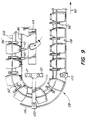
- FIG. 9 is a partial rear elevation view of the vaned conveyor and product cleaning station of the linear feeder of FIG. 1.
- FIG. 10 is a top plan view of the output conveyor of the linear feeder of FIG. 1.
- FIG. 11 is an enlarged partial front exploded isometric view of the vaned conveyor of the linear feeder of FIG. 1.
- FIG. 1 is a front isometric view of a
linear feeder 20 embodying the invention. FIGS. 2-10 and 6A are enlarged partial views which illustrate specific components and operation offeeder 20. -
Linear feeder 20 is generally comprised of aprefeeder 22, apreorientation chute 23, asingulation station 24, anorientation station 26, a cleaning station 28 (see FIG. 9) and anoutput conveyor 30, mounted together on aframe 21. -
Prefeeder 22 includes aprefeed conveyor 32 formetering articles 34 such as plastic bottles from asupply hopper 36, mounted adjacent the prefeed conveyor, topreorientation chute 23.Supply hopper 36 includes downwardly and inwardly slopingside walls 38, a plurality ofrigid grates 40 and a plurality of flexible grates 42 mounted across lower opening ofhopper 36 adjacent the top surface ofprefeed conveyor 32. Slopingside walls 38 and flexible grates 42 are designed tometer articles 34 in a smooth, steady fashion fromhopper 36 toconveyor 32 and into downwardly slopingpreorientation chute 23 which is preferably, but need not be, aligned substantially parallel to the prefeed conveyor, and which has a "washboard configuration" as illustrated in the cross-sectional view of FIG. 2. By "washboard configuration" is meant thatchute 23 is divided into a plurality oflongitudinal lanes 44 having slopingwalls 46.Walls 46 meet in a plurality ofpeaks 45 andvalleys 47 which preferably follow concentric arcs R1 and R2 designed to urge articles toward the center ofchute 23.Peaks 45 are preferably radiused to prevent them from damaging tumbling articles. Asarticles 34 tumble intochute 23, the provision oflongitudinal lanes 44 tends to naturally rotatedarticles 34 with their axes A (see FIG. 3 also) arranged substantially longitudinally, i.e., substantially in the downstream direction indicated by thearrow 60, with respect tochute 23. The provision of slopingwalls 46 in downwardly slopingchute 23 further tends to arrangearticles 34 lying on their sides withinlanes 44. - Returning to FIG. 1,
articles 34 tending to lie on their sides withinlongitudinal lanes 44 slide from downwardly slopingchute 23 and intopockets 50 on aconveyor 52 at aloading zone 54. In the region ofloading zone 54,conveyor 52 is preferably substantially horizontal to facilitate pocket loading.Conveyor 52 is aligned substantially perpendicular tochute 23, and thedownstream direction 60 changes accordingly so thatarticles leaving lanes 44 can slide directly into the pockets which are transversely arranged onconveyor 52. Preferably,conveyor 52 is a vaned conveyor provided with a plurality of spaced-apart vanes, blades, paddles or the like 56 which form andseparate pockets 50.Pockets 50 ofconveyor 52 are preferably sized to hold two ormore articles 34 lying end to end on their sides. - It is understood that not all
articles 34 are properly preoriented inlanes 44 ofchute 23 and similarly that not all articles are properly loaded into everypocket 50 onconveyor 52. Thus,chute 23 andloading zone 54 will very likely include afew articles 34a which tumble downchute 23 orconveyor 52. In this regard,loading zone 54 includes side walls (not shown) which preventarticles 34a from cascading offconveyor 52 and permit them to attempt to fill empty pocket spaces.Loading zone 54 preferably also includes a sensor (not shown) for slowing or stoppingprefeed conveyor 32 most preferably by a controller (also not shown) to slow or stop delivery ofarticles 34 toloading zone 54. It has been determined that maximum loading efficiency is attained when the speed ofprefeed conveyor 32 is adjusted to supply a relatively steady stream ofarticles 34 toloading zone 54 which prevents an excessive buildup ofarticles 34a necessitating frequent starting and stopping of the prefeed conveyor. - Downstream of, i.e., in the direction of
arrows 60 fromloading zone 54,vaned conveyor 52 slopes upwardly towardsingulation station 24. Referring to FIG. 3, the angle alpha of inclination ofconveyor 52 is preferably selected together with the height v to which vanes 56 extend abovesurface 53 ofvaned conveyor 52 such thatarticles 34b loaded inpockets 50 in a standing as opposed to a lying position will tend to fall out ofpockets 50 by force of gravity as indicated byarrow 62. In applications where higher vanes are preferred, wherevaned conveyor 52 is level and does not slope, or where supplemental forces are required to remove standing articles from pockets, it is understood that air jets, wipers or other means may be provided to tip the articles out of the pockets, and that sensors may also be provided to identify such standing articles. - Height v of
vanes 56 is less than a distance d betweenconveyor surface 53 and the highest point on thelowest end 63 ofarticles 34 as they lie on their sides within pockets 50. Referring to FIG. 4, this is necessary so that wiper orguide rail 64 mounted aboveconveyor 52 and abovevanes 56 can shift orcam articles 34 regardless of whether lower ends 63 or higher ends 65 are abutting the guide. -
Guide 64 shifts articles transversely acrossconveyor surface 53 alongpockets 50 towardedge 66 ofconveyor 52 asvanes 56 carry the articles downstream. -
Guide 64 also functions to remove all but onearticle 34 from every pocket which is loaded with more than one article. As discussed above, pockets 50 are preferably sized to accommodate two ormore articles 34 aligned end to end acrosspocket conveyor 52. This is done to improve the chances that eachpocket 50 will include at least one article in order to maintain relatively constant machine throughput. It is understood that pockets occasionally may not be loaded with any articles and that unacceptable numbers of empty pockets may be remedied by increasing the speed ofprefeed conveyor 32. -
Guide 64 is mounted toconveyor frame 21 withbrackets 68.Downstream end 70 ofguide 64 is mounted a distance equal to about one article length l away fromedge 66 ofconveyor 52. Asguide 64shifts articles 34c in contact therewith towardconveyor edge 66, these articles shiftother articles 34d in the pocket offconveyor 52. As indicated byarrow 72,articles 34d shifted offconveyor 52 fall by gravity into a recirculation orrecycling chute 74.Articles 34c remain onconveyor 52 and form asingle file 75 of articles lying alongconveyor edge 66. Returning to FIG. 1,recycling chute 74 returns articles topreorientation chute 23,loading zone 54 and/orbulk storage hopper 36. It is understood that the number of articles returned bychute 74 will affect the speed at which prefeedconveyor 32 meters articles into the loading zone for maximum loading efficiency. - Referring now to FIGS. 5-8,
single file 75 of articles is conveyed further downstream toorientation station 26. FIGS. 5 and 6 depict operation ofstation 26 to orientarticles 34e in inputsingle file 75 having their heavier ends 80 initiallynearest conveyor edge 66. FIGS. 7 and 8 depict operation ofstation 26 to orientarticles 34f in inputsingle file 75 having their lighter ends 82 initiallynearest conveyor edge 66. It is understood that, in operation,single file 75 will include articles aligned in both directions, i.e., some with their lighter and some with their heavier ends initiallynearer conveyor edge 66. - Referring first to FIGS. 5 and 6,
articles 34e having their heavier ends 80 initiallynearer conveyor edge 66 are cammed or shifted by wiper or guide 83 overconveyor edge 66 such that heavier ends 80 will fall by gravity into adrop zone 84 and ontosupport surface 86.Surface 86 may comprise a conveyor surface but is preferably a stationary surface over which articles are moved by vane portions 56' which transversely extend beyondconveyor edge 66. - Referring now to FIGS. 7 and 8,
articles 34f having their lighter ends 82 initiallynearer conveyor edge 66 are transversely moved offconveyor 52 across adeadplate 88 and onto a shelf ordeadplate portion 90 by afluid jet 92 or other means such as a mechanical wiper.Conveyor surface 53,deadplate 88 and shelf are substantially all in planar alignment for smooth article transfer. Vane portions 56'move articles 34f alongdeadplate 88 anddeadplate portion 90. In this regard, vane portions 56' includeslits 106 for receiving and passing overdeadplate 88. It is understood that conveyors may be used instead of these deadplates, with or without vane portions 56'. All that is essential is transferringarticles 34f to a support surface on the opposite side ofdrop zone 84 fromconveyor edge 66. -
Shelf 90 is laterally spaced fromconveyor edge 66 and includes anarticle supporting surface 94 and anarticle stopping wall 96 which may include means for temporarily retaining transferred articles to prevent them from bouncing. Alternatively, the line pressure influid jet 92 or the angle or force of a mechanical wiper can be adjusted substantially to prevent articles from bouncing back. - The width w of supporting
surface 94 ofshelf 90 is sufficiently small such that heavier ends 80 of the articles will fall by gravity intodrop zone 84 and ontosupport surface 86. - In operation to orient a random input of
articles support surface 86, it is necessary to selectively control operation ofair jet 92 or other article moving means. Whetherair jet 92 needs to be ON to move an article toshelf 90 or OFF to allow an article to pass downstream toconveyor edge 66 depends upon the direction in which the article is aligned withinpocket 50, i.e., whether the lighter or heavier end of the article is initiallynearer conveyor edge 66. Determining the direction in which articles are lying within the pockets is called "qualification" and must be completed for each article arriving insingle file 75 atorientation station 26. - Qualification is accomplished by wiper or
guide rail 100 and sensor/switch 101 which analyze the size or shape of the article end initially further fromconveyor edge 66. It is understood that the article end initiallynearer conveyor edge 66 could also be qualified. Sensor/switch 101 may be provided as electro-optical or mechanical, however, electro-optical is preferred and fiber optic is most preferred due to their reliability and remote source. A controller (not shown) may be connected between sensor 101 andair jet 92 for switching the air jet ON or OFF according to logic which may be wired or programmed into the controller. - Once it has been determined in which direction
smaller end 63 of the article is aligned, the direction in which theheavier end 80 of the article is aligned is known since the correlation between article end size and article end weight is given from inspectingarticles 34. Alower edge 102 ofwiper 100 is mounted above conveyor surface 53 a very specific height which is greater than distance d (betweenconveyor surface 53 and the highest point on thelowest end 63 of articles) and less than distance D (betweenconveyor surface 53 and the highest point on thehighest end 65 of articles)(see FIGS. 3 and 8). This ensures that lower ends 63 of articles can always fit beneathwiper 100 and that higher ends 65 of articles insingle file 75 can not ever fit beneathwiper 100. - Referring again to FIGS. 5-8, ends 63 of articles aligned as 34f will pass under
wiper 100 and be sensed by sensor 101 which momentarily turnsair jet 92 on to move the article toshelf 90. Ends 65 of articles aligned as 34e will not extend underwiper 100 and thus not trip sensor 101 or turnair jet 92 ON and thus these articles are passed downstream. It is understood that different articles may have a different correlation of size and weight at their ends and thus may have a different switching scheme. For example, it may be necessary or desirable to turnair jet 92 momentarily OFF instead of momentarily ON. - Singulation and orientation of articles is accomplished according to a method including the steps of introducing articles into pockets on
conveyor 52, eliminating all but a single article from eachpocket 50, determining whether articles are lying in a first direction (34f) or a second direction (34e), movingarticles 34f to supportsurface 94, shiftingarticles 34e towardconveyor edge 66, and advancing the articles downstream with vane portions 56' whereby they fall by gravity intodrop zone 84. - In order to facilitate changeover to different articles, at
least guide 83,guide 100, sensor 101 andair jet 102 oforientation station 26 are adjustably mounted to atooling frame 97 suspended aboveconveyor 52. - Oriented
single file 105 ofarticles 34 is carried further downstream by vane portions 56' which slide heavier ends 80 of the articles overdrop zone surface 86. Referring to FIGS. 6 and 6A, vane portions 56' includeslits 106 for receiving a straighteningguide 108 mounted downstream ofwiper 83, downstream ofdeadplate portion 94, and on the opposite side of thedrop zone 84 fromconveyor edge 66. Straighteningguide 108 effectively narrowsdrop zone 84 anduprights articles 34 in orientedsingle file 105. It is understood thatdrop zone 84 must be slightly wider in one region to permit articles to tip thereinto than in another region in which the articles are retained in an upright position. - Referring to FIGS. 6A and 8, vane portions 56' transversely extend a distance Y from
conveyor edge 66 which is sufficient to convey articles moved toshelf 90. Similarly, vane portions 56' extend down into drop zone 84 a distance X sufficient to convey articles overdrop zone surface 86. It is understood that magnitudes of X and Y and their ratio may be varied as necessary to accommodate various articles. Further, the width s ofslit 116 may be varied or additional slits may be provided to accommodate a variety of guides, deadplates or the like as is necessary or desired. - In the example illustrated by the Figures,
articles 34 are bottles in which heavier ends 80 are also the tops or open ends. Thus, the open ends ofbottles 34 are oriented downward insingle file 105. This oriented, uprighted, single file is moved further downstream by vane portions 56' to cleaningstation 28 illustrated in FIG. 9. -
Cleaning station 28 lies along a recirculating portion 52', and at the rear side (see FIG. 1), ofconveyor 52. Recirculating conveyor portion 52' returns toloading zone 54. At cleaningstation 28support surface 86 includes a plurality ionizingair jets 112 connected to a pressurizedfluid source 114.Air jets 112 include a spark gap inside each nozzle and fill the bottles with ionized air to attract dust particles therein. The dust particles fall out of the bottles by gravity. - Next, a curving
guide plate 116 retains the bottles between vane portions 56' as they are turned over bottoms down on aninner surface 118 ofplate 116.Surface 118 becomes the support over which the bottles are slid tooutput conveyor 30.Guide plate 116 is mounted toconveyor frame 21 bybrackets 120. It is understood that not all articles and indeed not all bottles will need necessarily to be turned over. -
Single file 105 of oriented, uprighted and cleaned bottles is moved further downstream by vane portions 56' ontosurface 124 ofoutput conveyor 30 which diverges from the path of vane portions 56' and moves at a slightly greater linear speed thanconveyor 52 to pull a gap g between the bottles and vane portions 56' for easing the bottles out from betweenvanes 56.Slits 106 in vane portions 56' may also be used to receive a wiper or guide for camming bottles out from between the vanes, however, this can cause tipping of articles, especially where the upper portion of the articles is heavier than the lower portion as the articles stand uprighted on the output conveyor. -
Linear feeder 20 is designed to utilize vertical dimensions and a circuitous type processing path in order to provide a relatively simple machine having the smallest possible footprint. - Referring to FIG. 11, the assembly and construction of
conveyor 52 is illustrated.Conveyor 52 comprises a pair ofchains 126 each including a plurality oftabs 128 for mounting slats orplates 130 withfasteners 132.Conveyor surface 53 is comprised of theupper surfaces 134 of a plurality of slats 130 (only one shown in FIG. 11) mounted tochains 126. -
Upper surface 134 ofslat 130 includes at least one and preferably several grooves orslots 136 aligned transversely ofconveyor 52 for receiving anedge 138 ofvanes 56 to removably replaceably mount them therein. In this regard, by placingvanes 56 indifferent grooves 136 and by leaving a different number of empty grooves betweenadjacent vanes 56, pockets 50 (see FIG. 7) of different sizes may be provided to receive articles having different widths.Grooves 136 are dovetail grooves andvane edge 138 is a dovetail edge slidingly receivable in any one of the grooves onconveyor 52. The dovetail grooving providesvanes 56 with an interference fit to releasably secure them onconveyor 52, and with sufficient rigidity to retain articles inpockets 50 betweenvanes 56. -
Slats 130 also include means such as aball detent 140 for releasably lockingvanes 56 in the desiredslot 136.Ball detents 140 are extended throughholes 142 inslots 136 by a plate spring 144 mounted toslats 130 byfasteners 146.Vanes 56 include hollows (not shown) onedge 138 for receiving the spring-loaded balls to releasably lock the vane withinslot 136. It is understood thatball detents 140 are not strictly necessary and that other locking means including fasteners, friction, adhesives or the like may also be used. -
Conveyor 52 is illustrated as constructed fromchains 126 andslats 130, however, it is understood that a belt or other type conveyor provided with a plurality of transverse slots for receiving vanes is all that is necessary to permit relatively quick and easy adjustment of vane spacing without need for any tools or equipment to accommodate varying size articles inlinear feeder 20. - Although the invention has been described with reference to particular embodiments, features, materials of construction and the like, these are not intended to exhaust all possible features, and indeed many other modifications and variations will be ascertainable to those of skill in the art without departing from the scope of the invention as defined in the appended claims.
Claims (15)
- An apparatus for producing an oriented single file (105) of articles (34) comprising:a conveyor (52) having a plurality pockets (50) distributed in the direction of travel of the conveyor (52) and extending transversely of said direction of travel, for receiving articles (34) so as to lie in the pockets (50), aligned in first or second directions in which first ends (63) of the articles (34) are directed, respectively, away from, or towards, one edge (66) of said conveyor (52);switch means (100, 101) actuable by articles (34f) aligned in the pockets (50) in said first direction; andmeans (92), responsive to said switch means (100, 101), for moving articles (34f) aligned in said first direction, from the conveyor (52);characterised by:the pockets (50) being formed by a plurality of spaced-apart vanes (56), portions (56') of said vanes extending transversely beyond said one edge (66) of the conveyor (52);a lateral support surface (94) disposed below the level of said transversely extending vane portions (56') and spaced apart from said conveyor edge (66) to provide a drop zone (84) therebetween;transfer means, including said means (92) responsive to said switch means (100, 101), for moving articles (34f) aligned in the pockets (50) in said first direction, along the pockets (50) between said transversely extending vane portions (56') to the opposite side of the drop zone (84) from said conveyor edge (66) and onto said lateral support surface (94), from where said articles (34f) are caused to tip into the drop zone (84) with their first ends (63) down; andmeans (83) for causing articles (34e) aligned in the pockets (50) in said second direction to move along the pockets towards said conveyor edge (66) and tip therefrom into the drop zone (84) with their first ends (63) down;whereby the articles (34) which fall into the drop zone (84) have the same mutual orientation regardless of their initial orientation.
- The apparatus of claim 1, wherein said transfer means includes a support plate (88) beneath the vane portions (56'), extending between said conveyor edge (66) and lateral support surface (94) upstream of the drop zone (84), for supporting articles (34f) during transfer by said article moving means (92), between the vane portions (56'), from the conveyor (52) to the lateral support surface (94), said vane portions (56') being operable to advance the transferred articles (34f) downstream along the lateral support surface (94) to the drop zone (84) to cause said articles to tip into the drop zone (84).
- The apparatus of claim 1 or 2, including further vane portions (56') below the level of the lateral support surface (94) to define, with the first-mentioned upper vane portions, and with the lateral support surface (94) and conveyor edge (66), means for retaining articles (34f, 34e) tipped into the drop zone (84) in their first-ends-down orientation.
- The apparatus of claim 1, 2 or 3 for producing an oriented single file of articles having first ends (63) which are smaller than their second ends (65), wherein said switch means (100, 101) comprises a guide rail (100) disposed above said conveyor (52) a distance sufficient to permit the first, smaller ends (63) of articles (34) in said pockets (50) to fit beneath said guide rail (100).
- The apparatus of claim 4, wherein said switch means (100, 101) further comprises a sensor (101) for determining whether said first ends (63) of the articles (34) are extending beneath said guide rail (100).
- The apparatus of claim 4 or 5, wherein said guide rail (100) is disposed above said conveyor (52) a distance low enough such that the second, larger ends (65) of articles (34) in said pockets (50) are abutted by said guide rail (100) to shift the articles (34) toward the edge (66) of said conveyor (52).
- The apparatus of any of claims 4 to 6, including a second guide rail (64), disposed over said conveyor upstream of said article moving means (92), for creating a single file (75) of articles in said pockets (50).
- The apparatus of any preceding claim, wherein said article moving means (92) comprises a fluid jet.
- The apparatus of any preceding claim, wherein said conveyor (52) includes a plurality of transverse grooves (136) and wherein said vanes (56) are received in the grooves (136) to form said pockets (50).
- The apparatus of claim 9, wherein said grooves (136) are dovetail grooves and wherein said vanes (56) include a dovetail edge (138) for slidingly fitting said dovetail grooves (136).
- The apparatus of claim 9 or 10, including means (140) mounted to said conveyor for releasably locking said vanes (56) in said grooves (136).
- A method of producing an oriented single file (105) of articles (34) from a bulk supply (36), comprising the steps of:introducing articles (34) from the bulk supply (36) into transversely extending pockets (50) of a conveyor (52) so as to lie in said pockets, aligned in first or second directions in which first ends (63) of the articles are directed, respectively, away from, or towards, one edge (66) of the conveyor (52);determining whether articles (34) lying within said pockets are aligned in said first or said second direction; andmoving articles (34f) aligned in said first direction, from the conveyor (52);characterised by:moving such articles (34f) along the pockets (50) beyond the conveyor edge (66), to a lateral support surface (94) spaced from said conveyor edge (66), and advancing the articles (34f) downstream along the lateral support surface (94), causing such articles to tip from said lateral support surface (94), and fall by gravity with said first ends (63) down, into a drop zone (84) between said conveyor edge (66) and said lateral support surface (94); andmoving articles (34e) aligned in said second direction, along the pockets (50) towards the conveyor edge (66), and advancing the articles (34e) downstream along the conveyor edge (66), causing the latter articles (34e) to tip from said edge (66), and fall by gravity with said first ends down, into said drop zone (84);whereby the articles (34f, 34e) which fall into the drop zone (84) have the same mutual orientation regardless of their initial orientation.
- The method of claim 12, including, before the determining step, the step of eliminating all but one article from the pockets (50) of the conveyor (52) to provide a single file of articles (34) lying on their sides.
- The method of claim 12 or 13, including, before the introducing step, the steps of determining a width of the articles, and sliding vanes (56) into transverse grooves (136) on the conveyor (52) such that the vanes are spaced apart more than the article width to form pockets (50) for receiving articles.
- The method of claim 13, including, after the sliding step, the step of releasably locking the vanes (56) into the conveyor grooves (136).
Applications Claiming Priority (4)
| Application Number | Priority Date | Filing Date | Title |
|---|---|---|---|
| US956662 | 1992-10-02 | ||
| US07/956,662 US5236077A (en) | 1992-10-02 | 1992-10-02 | Linear feeder |
| US08/082,284 US5333716A (en) | 1992-10-02 | 1993-06-24 | Linear feeder for varying size articles |
| US82284 | 1993-06-24 |
Publications (2)
| Publication Number | Publication Date |
|---|---|
| EP0590774A1 EP0590774A1 (en) | 1994-04-06 |
| EP0590774B1 true EP0590774B1 (en) | 1997-04-02 |
Family
ID=26767284
Family Applications (1)
| Application Number | Title | Priority Date | Filing Date |
|---|---|---|---|
| EP93306436A Expired - Lifetime EP0590774B1 (en) | 1992-10-02 | 1993-08-16 | Apparatus for producing an oriented single file of articles |
Country Status (6)
| Country | Link |
|---|---|
| US (1) | US5333716A (en) |
| EP (1) | EP0590774B1 (en) |
| JP (1) | JPH06234411A (en) |
| AT (1) | ATE151048T1 (en) |
| CA (1) | CA2104199A1 (en) |
| DE (1) | DE69309381T2 (en) |
Families Citing this family (16)
| Publication number | Priority date | Publication date | Assignee | Title |
|---|---|---|---|---|
| US5586637A (en) * | 1994-02-22 | 1996-12-24 | Aidlin; Samuel S. | Variable angle conveyor assembly with stepped cleat |
| US6017496A (en) | 1995-06-07 | 2000-01-25 | Irori | Matrices with memories and uses thereof |
| US6329139B1 (en) | 1995-04-25 | 2001-12-11 | Discovery Partners International | Automated sorting system for matrices with memory |
| JP2001106332A (en) * | 1999-10-11 | 2001-04-17 | Yoshitaka Aoyama | Ejection device for abnormal projection nut |
| DE10041241B4 (en) * | 2000-08-22 | 2008-02-07 | Grecon Dimter Holzoptimierung Nord Gmbh & Co. Kg | Aligning and feeding device for plate-like workpieces |
| US6491152B1 (en) | 2001-04-09 | 2002-12-10 | Gebo Corporation | Conveyor assembly |
| US7246695B2 (en) * | 2005-09-14 | 2007-07-24 | Alcoa Closure Systems International, Inc. | Conveyor apparatus for conveying closure |
| US7597189B2 (en) * | 2006-10-25 | 2009-10-06 | Fowler Products Company Llc | Cap sorter and associated cleat |
| WO2011121812A1 (en) * | 2010-03-30 | 2011-10-06 | 株式会社草野科学 | Chip transfer device |
| JP5898119B2 (en) * | 2013-03-28 | 2016-04-06 | シスメックス株式会社 | Analysis equipment |
| US20160176571A1 (en) * | 2013-05-31 | 2016-06-23 | Wrh Walter Reist Holding Ag | Packaging body having a rollable outer shape and method for producing a packaging unit having said type of packaging body |
| ES2534423B1 (en) | 2013-10-21 | 2016-01-26 | Tomás MULET VALLES | Packaging supplier machine |
| DE102021129997A1 (en) * | 2021-11-17 | 2023-05-17 | HTI Automation GmbH | separation device |
| AU2024237962A1 (en) * | 2023-03-22 | 2025-09-18 | Innovation Associates, Inc. | Medication container sorting system and apparatus |
| CN117699386B (en) * | 2024-02-06 | 2024-04-26 | 长治凌燕机械厂 | Upper and lower buttress conveyer |
| GB2638209A (en) * | 2024-02-15 | 2025-08-20 | Sita B V | Diverting conveyor device |
Family Cites Families (30)
| Publication number | Priority date | Publication date | Assignee | Title |
|---|---|---|---|---|
| US2771191A (en) * | 1953-01-19 | 1956-11-20 | Lilly Co Eli | Capsule selector and rectifier mechanism |
| US3031059A (en) * | 1958-10-13 | 1962-04-24 | Deering Milliken Res Corp | Bobbin handling apparatus |
| US2970683A (en) * | 1959-07-02 | 1961-02-07 | Sylvania Electric Prod | Article handling apparatus |
| US3101832A (en) * | 1961-04-07 | 1963-08-27 | Emhart Mfg Co | Unscrambler and erector for articles such as plastic bottles |
| US3066784A (en) * | 1961-05-19 | 1962-12-04 | Peerless Tube Company | Conveyors |
| US3331486A (en) * | 1966-04-27 | 1967-07-18 | Giorgio Corp Di | Bottle handling apparatus |
| US3392815A (en) * | 1966-07-14 | 1968-07-16 | Unscrambler Corp Of New Jersey | Unscrambling and orienting apparatus |
| US3367477A (en) * | 1966-10-28 | 1968-02-06 | California Packing Corp | Apparatus for orienting tapered agricultural products |
| US3658167A (en) * | 1970-06-11 | 1972-04-25 | Frank Zabroski | Method of and device for conveying and arrangeing empty receptacles, such as bottles or jars |
| US3707217A (en) * | 1970-09-08 | 1972-12-26 | American Flange & Mfg | Method in apparatus for feeding closures |
| US3722659A (en) * | 1971-10-07 | 1973-03-27 | Aidlin Automation | Apparatus for orienting and feeding bottles or like articles |
| US3797640A (en) * | 1972-01-24 | 1974-03-19 | S Aidlin | Automatic apparatus for orienting and feeding bottles or like articles having necks |
| US3738473A (en) * | 1972-03-22 | 1973-06-12 | Rowe International Inc | Centering mechanism for component sequencing machine |
| US3833111A (en) * | 1973-04-23 | 1974-09-03 | Pneumatic Scale Corp | Container-orienting apparatus |
| US3912120A (en) * | 1973-03-26 | 1975-10-14 | Hoppmann Corp | Centrifugal method of sorting and orienting particulate articles |
| NL7315703A (en) * | 1973-11-15 | 1975-05-20 | Brouwer & Co Machine | DEVICE FOR THE TARGETED DISCHARGE OF CONICAL OBJECTS. |
| US3954171A (en) * | 1974-07-11 | 1976-05-04 | Monsanto Company | Linearly disposed method and apparatus for orienting articles in a pre-selected end-to-end position |
| US4201285A (en) * | 1976-07-14 | 1980-05-06 | Fmc Corporation | Automatic corn cutter feeder |
| US4082177A (en) * | 1976-10-21 | 1978-04-04 | Aidlin Samuel S | Container conveying apparatus |
| US4094412A (en) * | 1976-11-30 | 1978-06-13 | Hoppmann Corporation | Rolling method of sorting particulate articles |
| US4208761A (en) * | 1978-01-24 | 1980-06-24 | New England Machinery, Inc. | Bottle conveying and cleaning apparatus |
| US4362234A (en) * | 1980-10-06 | 1982-12-07 | Mcdonald Walter | High speed cap orienting and feeding apparatus |
| EP0054775B1 (en) * | 1980-12-23 | 1984-11-28 | Maschinenfabrik Rieter Ag | Device for sorting conical bobbins |
| US4440286A (en) * | 1981-03-13 | 1984-04-03 | Avdel Limited | Orientating device |
| FR2536050A1 (en) * | 1982-11-12 | 1984-05-18 | Applic Vibration | Dispenser for tubular casings |
| US4832183A (en) * | 1984-08-20 | 1989-05-23 | The Laitram Corporation | Conveyor belt having insertable & selectable conveying member |
| US4829751A (en) * | 1986-09-09 | 1989-05-16 | Tisma Machine Corporation | Apparatus with replaceable trays on automatic packaging machines |
| US4821920A (en) * | 1987-08-28 | 1989-04-18 | Hoppmann Corporation | Method and apparatus for loading articles onto feeder by elevating ramp segments |
| US5127514A (en) * | 1991-09-10 | 1992-07-07 | Peter Guttinger | Variable width conveyor bucket |
| US5236077A (en) * | 1992-10-02 | 1993-08-17 | Hoppmann Corporation | Linear feeder |
-
1993
- 1993-06-24 US US08/082,284 patent/US5333716A/en not_active Expired - Fee Related
- 1993-08-16 DE DE69309381T patent/DE69309381T2/en not_active Expired - Fee Related
- 1993-08-16 AT AT93306436T patent/ATE151048T1/en not_active IP Right Cessation
- 1993-08-16 EP EP93306436A patent/EP0590774B1/en not_active Expired - Lifetime
- 1993-08-16 CA CA002104199A patent/CA2104199A1/en not_active Abandoned
- 1993-08-17 JP JP5234348A patent/JPH06234411A/en active Pending
Also Published As
| Publication number | Publication date |
|---|---|
| US5333716A (en) | 1994-08-02 |
| ATE151048T1 (en) | 1997-04-15 |
| JPH06234411A (en) | 1994-08-23 |
| CA2104199A1 (en) | 1994-04-03 |
| EP0590774A1 (en) | 1994-04-06 |
| DE69309381T2 (en) | 1997-10-23 |
| DE69309381D1 (en) | 1997-05-07 |
Similar Documents
| Publication | Publication Date | Title |
|---|---|---|
| US5236077A (en) | Linear feeder | |
| US5333716A (en) | Linear feeder for varying size articles | |
| KR101932058B1 (en) | Shift and hold conveyor assembly for removal of oversize parcels | |
| JP6333394B2 (en) | Singulator conveyor system for large bags of hard and small parcels | |
| EP1281643B1 (en) | Automatic linear machine for orienting and aligning articles | |
| US6345487B1 (en) | High quality control tablet filler device | |
| JPH03264419A (en) | Machine for automatically positioning and supplying container | |
| JPH08268535A (en) | Transport mechanism and transport method | |
| JPH08169539A (en) | Article separation method and separation supply apparatus | |
| US6516938B1 (en) | Lane guide | |
| JP2017006826A (en) | Fruit-vegetable automatic sorting method, fruit-vegetable automatic sorting apparatus, packing apparatus, fruit-vegetable sorting packing apparatus, and fruit-vegetable carrier | |
| US5404991A (en) | Article orienting device | |
| US4586598A (en) | Method and apparatus for delivering articles from a high-speed production machine | |
| US5191741A (en) | Fluidized bed bottle filling system | |
| CA1126769A (en) | Article counting machine | |
| US3955680A (en) | Apparatus and method for segregating different size articles | |
| KR100556009B1 (en) | Dispensing supply apparatus and method | |
| US6582180B2 (en) | Separating conveyor for stacked objects | |
| US5133445A (en) | Device for feeding commodities in succession | |
| US20050072654A1 (en) | Conveyor assembly | |
| EP0760714A1 (en) | Apparatus and method of feeding and sorting objects | |
| JPS6380887A (en) | Small vegetable and fruit extractor for vegetable and fruit | |
| JPH08188230A (en) | Article turning-over equipment | |
| JP2000313520A (en) | Feeder of long tapered hollow molding and method for supplying long tapered hollow molding in small quantities | |
| EP1012042B1 (en) | Tray filler with indexable swing arm conveyor |
Legal Events
| Date | Code | Title | Description |
|---|---|---|---|
| PUAI | Public reference made under article 153(3) epc to a published international application that has entered the european phase |
Free format text: ORIGINAL CODE: 0009012 |
|
| AK | Designated contracting states |
Kind code of ref document: A1 Designated state(s): AT BE CH DE DK ES FR GB GR IE IT LI LU MC NL PT SE |
|
| 17P | Request for examination filed |
Effective date: 19941006 |
|
| 17Q | First examination report despatched |
Effective date: 19951018 |
|
| GRAG | Despatch of communication of intention to grant |
Free format text: ORIGINAL CODE: EPIDOS AGRA |
|
| GRAH | Despatch of communication of intention to grant a patent |
Free format text: ORIGINAL CODE: EPIDOS IGRA |
|
| GRAH | Despatch of communication of intention to grant a patent |
Free format text: ORIGINAL CODE: EPIDOS IGRA |
|
| GRAA | (expected) grant |
Free format text: ORIGINAL CODE: 0009210 |
|
| AK | Designated contracting states |
Kind code of ref document: B1 Designated state(s): AT BE CH DE DK ES FR GB GR IE IT LI LU MC NL PT SE |
|
| PG25 | Lapsed in a contracting state [announced via postgrant information from national office to epo] |
Ref country code: NL Effective date: 19970402 Ref country code: LI Effective date: 19970402 Ref country code: IT Free format text: LAPSE BECAUSE OF FAILURE TO SUBMIT A TRANSLATION OF THE DESCRIPTION OR TO PAY THE FEE WITHIN THE PRESCRIBED TIME-LIMIT;WARNING: LAPSES OF ITALIAN PATENTS WITH EFFECTIVE DATE BEFORE 2007 MAY HAVE OCCURRED AT ANY TIME BEFORE 2007. THE CORRECT EFFECTIVE DATE MAY BE DIFFERENT FROM THE ONE RECORDED. Effective date: 19970402 Ref country code: GR Free format text: LAPSE BECAUSE OF FAILURE TO SUBMIT A TRANSLATION OF THE DESCRIPTION OR TO PAY THE FEE WITHIN THE PRESCRIBED TIME-LIMIT Effective date: 19970402 Ref country code: FR Effective date: 19970402 Ref country code: ES Free format text: THE PATENT HAS BEEN ANNULLED BY A DECISION OF A NATIONAL AUTHORITY Effective date: 19970402 Ref country code: DK Effective date: 19970402 Ref country code: CH Effective date: 19970402 Ref country code: BE Effective date: 19970402 Ref country code: AT Effective date: 19970402 |
|
| REF | Corresponds to: |
Ref document number: 151048 Country of ref document: AT Date of ref document: 19970415 Kind code of ref document: T |
|
| REG | Reference to a national code |
Ref country code: CH Ref legal event code: EP |
|
| REF | Corresponds to: |
Ref document number: 69309381 Country of ref document: DE Date of ref document: 19970507 |
|
| PG25 | Lapsed in a contracting state [announced via postgrant information from national office to epo] |
Ref country code: SE Effective date: 19970702 Ref country code: PT Effective date: 19970702 |
|
| REG | Reference to a national code |
Ref country code: IE Ref legal event code: FG4D Free format text: 72996 |
|
| PG25 | Lapsed in a contracting state [announced via postgrant information from national office to epo] |
Ref country code: LU Free format text: LAPSE BECAUSE OF NON-PAYMENT OF DUE FEES Effective date: 19970816 Ref country code: IE Free format text: LAPSE BECAUSE OF NON-PAYMENT OF DUE FEES Effective date: 19970816 |
|
| PGFP | Annual fee paid to national office [announced via postgrant information from national office to epo] |
Ref country code: GB Payment date: 19970818 Year of fee payment: 5 |
|
| EN | Fr: translation not filed | ||
| NLV1 | Nl: lapsed or annulled due to failure to fulfill the requirements of art. 29p and 29m of the patents act | ||
| REG | Reference to a national code |
Ref country code: CH Ref legal event code: PL |
|
| PLBE | No opposition filed within time limit |
Free format text: ORIGINAL CODE: 0009261 |
|
| STAA | Information on the status of an ep patent application or granted ep patent |
Free format text: STATUS: NO OPPOSITION FILED WITHIN TIME LIMIT |
|
| PG25 | Lapsed in a contracting state [announced via postgrant information from national office to epo] |
Ref country code: MC Free format text: LAPSE BECAUSE OF NON-PAYMENT OF DUE FEES Effective date: 19980228 |
|
| 26N | No opposition filed | ||
| PG25 | Lapsed in a contracting state [announced via postgrant information from national office to epo] |
Ref country code: GB Free format text: LAPSE BECAUSE OF NON-PAYMENT OF DUE FEES Effective date: 19980816 |
|
| GBPC | Gb: european patent ceased through non-payment of renewal fee |
Effective date: 19980816 |
|
| PGFP | Annual fee paid to national office [announced via postgrant information from national office to epo] |
Ref country code: DE Payment date: 20010914 Year of fee payment: 9 |
|
| PG25 | Lapsed in a contracting state [announced via postgrant information from national office to epo] |
Ref country code: DE Free format text: LAPSE BECAUSE OF NON-PAYMENT OF DUE FEES Effective date: 20030301 |