EP0590554B1 - Vacuum lift device - Google Patents
Vacuum lift device Download PDFInfo
- Publication number
- EP0590554B1 EP0590554B1 EP93115517A EP93115517A EP0590554B1 EP 0590554 B1 EP0590554 B1 EP 0590554B1 EP 93115517 A EP93115517 A EP 93115517A EP 93115517 A EP93115517 A EP 93115517A EP 0590554 B1 EP0590554 B1 EP 0590554B1
- Authority
- EP
- European Patent Office
- Prior art keywords
- control valve
- lift tube
- opening
- vacuum
- lift
- Prior art date
- Legal status (The legal status is an assumption and is not a legal conclusion. Google has not performed a legal analysis and makes no representation as to the accuracy of the status listed.)
- Expired - Lifetime
Links
- 230000000284 resting effect Effects 0.000 claims description 4
- 230000000063 preceeding effect Effects 0.000 claims 2
- 230000006835 compression Effects 0.000 description 4
- 238000007906 compression Methods 0.000 description 4
- 230000008602 contraction Effects 0.000 description 4
- 210000003254 palate Anatomy 0.000 description 1
- 230000002093 peripheral effect Effects 0.000 description 1
- 238000005096 rolling process Methods 0.000 description 1
- 125000006850 spacer group Chemical group 0.000 description 1
Images




Classifications
-
- B—PERFORMING OPERATIONS; TRANSPORTING
- B66—HOISTING; LIFTING; HAULING
- B66F—HOISTING, LIFTING, HAULING OR PUSHING, NOT OTHERWISE PROVIDED FOR, e.g. DEVICES WHICH APPLY A LIFTING OR PUSHING FORCE DIRECTLY TO THE SURFACE OF A LOAD
- B66F3/00—Devices, e.g. jacks, adapted for uninterrupted lifting of loads
- B66F3/24—Devices, e.g. jacks, adapted for uninterrupted lifting of loads fluid-pressure operated
- B66F3/25—Constructional features
- B66F3/35—Inflatable flexible elements, e.g. bellows
-
- B—PERFORMING OPERATIONS; TRANSPORTING
- B66—HOISTING; LIFTING; HAULING
- B66C—CRANES; LOAD-ENGAGING ELEMENTS OR DEVICES FOR CRANES, CAPSTANS, WINCHES, OR TACKLES
- B66C1/00—Load-engaging elements or devices attached to lifting or lowering gear of cranes or adapted for connection therewith for transmitting lifting forces to articles or groups of articles
- B66C1/02—Load-engaging elements or devices attached to lifting or lowering gear of cranes or adapted for connection therewith for transmitting lifting forces to articles or groups of articles by suction means
- B66C1/0212—Circular shape
-
- B—PERFORMING OPERATIONS; TRANSPORTING
- B66—HOISTING; LIFTING; HAULING
- B66C—CRANES; LOAD-ENGAGING ELEMENTS OR DEVICES FOR CRANES, CAPSTANS, WINCHES, OR TACKLES
- B66C1/00—Load-engaging elements or devices attached to lifting or lowering gear of cranes or adapted for connection therewith for transmitting lifting forces to articles or groups of articles
- B66C1/02—Load-engaging elements or devices attached to lifting or lowering gear of cranes or adapted for connection therewith for transmitting lifting forces to articles or groups of articles by suction means
- B66C1/0293—Single lifting units; Only one suction cup
Definitions
- the present invention relates to a vacuum lift device.
- a known vacuum lift device (JP-U-62-25344 or US-A-4 412 775) comprises a vacuum operated type lift tube which is able to expand and contract in an upward and downward direction, and a lift tube expansion control valve controlling the level of vacuum in the lift tube by controlling the opening area of the atmospheric opening of the lift tube to cause the lift tube to expand and contract in an upward and downward direction.
- a vacuum lift device for example, an object to be lifted is initially sucked and held by the lower end portion of the lift tube, and then the object is lifted by contracting the lift tube by operating the lift tube expansion control valve. Then, the object thus lifted is maintained at a desired height by operating the lift tube expansion control valve. Then, the object is caused to move to another place in a state where the object is maintained at a desired height. Then, the object is lowered and placed there.
- a contraction control for lifting the object As mentioned above, a contraction control for lifting the object, a contraction and expansion stopping control for maintaining the object at a desired height and an expansion control for lowering the object are required for the lift tube.
- these three controls are carried out by using only the lift tube expansion control valve.
- the lift tube expansion control valve is completely closed when the level of vacuum in the lift tube is to be made maximum, and the lift tube expansion control valve is fully opened when the level of vacuum in the lift tube is to be made minimum.
- the opening area of the atmospheric opening, obtained when the lift tube expansion control valve is fully open is normally made relatively large. Namely, to quickly expand and contract the lift tube, the control range of the opening area by the lift tube expansion control valve is normally made considerably wide, and therefore, if the lift tube expansion control valve is slightly displaced, the opening area of the atmospheric opening changes considerably.
- the level of vacuum in the lift tube must be maintained at a constant level corresponding to the weight of the object. Namely, in this case, if the level of vacuum in the vacuum lift becomes slightly higher than this constant level, the lift tube contracts and, if the level of vacuum in the vacuum lift becomes slightly lower than this constant level, the lift tube expands. That is, to maintain the object at a desired height, the precise control of the opening area of the atmospheric opening is required.
- An object of the present invention is to provide a vacuum lift device capable of property maintaining an object lifted by the vacuum lift to a desired hight.
- a vacuum lifting device comprising a vacuum operated type lift tube which is able to expand and contract in an upward and downward direction, and a lift tube expansion control valve controlling the level of vacuum in the lift tube by controlling the opening area of the atmospheric opening of the lift tube to cause the lift tube to expand and contract in an upward and downward direction
- a hovering control valve controlling the flow area between the outside space and the interior of the lift tube to maintain an object lifted by the lift tube at a desired height is provided separately from the lift tube expansion control valve.
- the expansion and contraction control of the lift tube is carried out by the lift tube expansion control valve which is capable of greatly changing the opening area of the atmospheric opening, and the expansion and contraction stopping control of the lift tube for maintaining the object at a desired height is carried out by the hovering control valve which is capable of carrying out the precise control of the flow area between the outside space and the interior of the lift tube.
- the two atmospheric openings can be completely closed by the control valve.
- the vacuum lift device comprises spring means for maintaining the control valve at a stable position in which the first atmospheric opening is closed by the lift tube control valve and in which the second atmospheric opening is open when said lift tube control valve is in a free state.
- the lift tube has a flat side wall on which the first atmospheric opening and the second atmospheric opening are formed, and the first atmospheric opening is spaced from the second atmospheric opening via a band-like side wall portion, the lift tube control valve being pivotally supported by a pivot on the lift tube and having a valve plate which is slidable on the flat side wall, a lower edge of the valve plate being positioned in the band-like side wall portion when the lift tube control valve is in the free state.
- the lift tube control valve has a spring retainer on the atmospheric openings side with respect to the pivot, and the spring means comprises a tension spring extending from the spring retainer in a direction opposite to the pivot, one end of the tension spring being supported by the spring retainer, the other end of the tension spring being supported by the lift tube.
- the lift tube control valve has a spring retainer on the atmospheric openings side with respect to the pivot, and the spring means comprises a spring rod extending from the spring retainer toward the pivot side, one end of the spring rod being supported by the spring retainer, the other end of the spring rod being fixed to the lift tube.
- the spring retainer comprises a pair of spaced support pins, and the one end of the spring rod is inserted between the support pins.
- the spring retainer comprises a support pin having a slot formed thereon, and the one end of the spring rod is inserted into the slot.
- the spring rod has a wound portion at an intermediate portion thereof, and the wound portion is fitted around the pivot.
- the lift tube control valve has a roller roling on the side wall and rotatably supported by an end portion of the lift tube control valve, which is located furthest from the pivot, to slightly float the lift tube control valve from the side wall.
- the atmospheric opening comprises a first atmospheric opening and a second atmospheric opening
- the hovering control means controls a flow area of an air flowing within the second atmospheric opening.
- the hovering control means comprises an air flow passage formed between the interior of the lift tube and the second atmospheric opening, and a rotary valve having a threaded portion which projects into and retracts from the air flow passage.
- the hovering control means directly cooperates with the second atmospheric opening to control the flow area of an air flowing within the second atmospheric opening.
- the hovering control means comprises a slide valve which is able to control an opening area of the second atmospheric opening.
- the hovering control means comprises a manually operated rotary operation portion arranged outside of the lift tube, and a mechanism for changing the rotation of the operation portion to the sliding movement of the slide valve.
- the hovering control means comprises a valve plate pivotally supported by the lift tube and arranged to cover the second atmospheric opening.
- the hovering control means comprises a manually operated rotary operation portion arranged outside of the lift tube, and a mechanism for changing the rotation of the operation portion to the pivotal movement of the valve plate.
- the opening area of the atmospheric opening can be greatly changed by the lift tube expansion control valve, it is possible to quickly contract and expand the lift tube.
- the level of vacuum in the lift tube can be precisely controlled by the hovering control valve, it is possible to properly maintain the object at a desired height.
- control valve is a pivotable valve plate slideable in the flow areas of the opening and the opening.
- valve plate is pivotable mounted on a support shaft and is fixed to a tension spring with its projecting end.
- tension spring is mounted substantially in a radial direction with reference to the support shaft of the valve plate.
- valve plate is pivotally mounted on a support shaft and is held in a resting position by means of a leave spring extending substantially parallel to the longitudinal axis of the valve plate. Thereby the end of the leave spring mounted to the valve plate is held between to opposed rollers.
- valve plate is pivotally mounted on a support shaft and a spiral spring is mounted on this shaft, wherein one arm of this spiral spring is fixed to the valve plate and the other arm is fixed to the suction controll apparatus, such that the control valve is held in a resting position by means of the spiral spring.
- a vacuum lift device comprises a lift tube 1 made of a flexible material and expandable in the axial direction thereof, i.e., in an upward and downward direction, a cylindrical casing 2 attached to the upper end portion of the lift tube 1, and a suction control apparatus 3 attached to the lower end portion of the lift tube 1.
- the cylindrical casing 2 is hung on a support member 4 fixed to a support beam or supported by the support beam so that it is able to move in the horizontal direction.
- the suction control apparatus 3 has at its lower end a suction pad 6 for sucking and holding an object 5 to be lifted.
- the interior of the lift tube 1 is connected to the suction pump (not shown) via a conduit 7, and air in the lift tube 1 is continuously sucked by this suction pump. Accordingly, vacuum is normally produced in the lift tube 1.
- the suction control apparatus 3 comprises four side walls 8a, 8b, 8c, 8d, a bottom wall 9, a flange portion 10 extending inward from the upper ends of the side walls 8a, 8b, 8c, 8d, and a cylindrical portion 11 fixed onto the flange portion 10.
- the lower end portion of the lift tube 1 is fixed to the outer circumferential wall of the cylindrical portion 11 in an air tight manner. Accordingly, the interior chamber 13 of the suction control apparatus 3, which is surrounded by the side walls 8a, 8b, 8c, 8d, the cylindrical portion 11 and the bottom wall 9, is in communication with the interior of the lift tube 1, and accordingly, vacuum is produced normally in the interior chamber 13.
- Grip portions 14, 15 each having a U shape are fixed to the outer side faces of the side walls 8b, 8d, respectively.
- an opening 16 having a circular shape is formed on the bottom wall 9 and covered by a pair of disc plates 17, 18 having a diameter which is larger than that of the opening 16.
- These disc plates 17, 18 are rotatably mounted on the lower end portion of a rod 19 which extends upward in the interior chamber 13.
- the upper portion of the rod 19 is supported by rod guide members 20 fixed to the flange portion 10 so that the rod 19 is able to move in the axial direction thereof.
- the rod 19 is biased downward by a compression spring 21 which is inserted around the rod 19, and thus, a pair of the disc plates 17, 18 are seated on the bottom wall 9 due to the spacing force of the compression spring 21. Accordingly, the opening 16 is normally closed by a pair of the disc plates 17, 18.
- the pair of the disc plates 17, 18 are mounted on the rod 19 so that they are able to relatively rotate about the rod 19, and these disc plates 17, 18 are caused to relatively rotate by a pin 23 fixed to the disc plate 18 and projecting downward through a slot 22 formed on the disc plate 17.
- a frame 26 having a rectangular shape projects in a transverse direction from the outer peripheral edge of the side wall 8a, and thus the outer side face of the side wall 8a is such that it is surrounded by the frame 26.
- a first atmospheric opening 28 having a large area and a second atmospheric opening 29 having a small area, which openings are spaced via a band-like side wall portion 27, are formed on the side wall 8a, and a lift tube expansion control valve 30 for controlling the opening areas of these atmospheric openings 28, 29 is arranged in the frame 26.
- This lift tube expansion control valve 30 comprises a flat valve plate 31 movable along the outer face of the side wall 8a, and a lever 32 supporting the valve plate 31.
- the lever 32 is rotatably mounted on a support shaft 34 via a radial bearing 33. In addition, this lever 32 is supported by a nut 36 via a thrust bearing 35.
- the lever 32 extends through the frame 26 and projects outward therefrom, and an operation arm 37 having a U shape is fixed to the projecting portion of the lever 32.
- the end portion of the operation arm 37 is supported on the side wall 8c via a pivot pin 38 which is arranged coaxially with the support shaft 34.
- the operation arm 37 has another operation arm 39 extending upward therefrom.
- the lever 32 and the valve plate 31 are rotated about the support shaft 34 by operating one of the operation arms 37 and 39.
- a spring retainer 40 projecting outward is fixed to the inner end portion of the lever 32, and another spring retainer 41 is fixed to the frame 26 located on an opposite side of the support shaft 34 with respect to the spring retainer 40.
- a tension spring 42 is arranged between these spring retainers 40 and 41. Accordingly, the lever 32 is normally maintained at a position such that the spring retainers 40 and 41 and the support shaft 34 are located on a straight line due to the spring force of the tension spring 42, as illustrated in Fig. 4.
- the position of the spring retainer 41 is determined so that the lower edge of the valve plate 31 is located half way on the height of the band-like side wall portion 27 when the spring retainers 40 and 41 and the support shaft 34 are located on the straight line.
- the first atmospheric opening 28 is formed at a position such that it is completely covered by the valve plate 31 when the spring retainers 40 and 41 and the support shaft 34 are located on the straight line. If the valve plate 31 is caused to rotate in a clock wise direction against the spring force of the tension spring 42 by operating the operation arms 37, 39, the first atmospheric opening 28 is caused to be open to the outside space. Conversely, if the valve plate 31 is caused to rotate in a counter-clockwise direction against the spring force of the tension spring 42 by operating the operation arms 37, 39, the second atmospheric opening 29 is also covered by the valve plate 31 in addition to the first atmospheric opening 28. The second atmospheric opening 29 is formed at a position such that it can be completely covered by the valve plate 31 when the valve plate 31 is rotated in a counter-clockwise direction.
- Figure 6 illustrates the case where the spring retainer 41 and the tension spring 42 are removed.
- a roller support plate 44 is fixed to the valve plate 31 via spacers 45, and a pair of rollers 43 each rolling on the outer face of the side wall 8a are rotatably supported by the roller support plate 44.
- the valve plate 31 is slightly floated from the outer wall of the side wall 8a by the rollers 43.
- valve plate 31 Since the valve plate 31 is slightly floated from the outer face of the side wall 8a as mentioned above; the inner tip end of the valve plate 31 is supported on the outer face of the side wall 8a via the rollers 43; and the lever 32 is supported by the support shaft 34 via the radial bearing 33 and the thrust bearing 35, it is possible to rotate the lift tube expansion control valve 30 with an extremely small operation power.
- a block 46 is arranged on the inner face of the side wall 8a so as to cover the second atmospheric opening 29, and a connecting bore 47 interconnecting the second atmospheric opening 29 to the interior chamber 13 is formed in the block 46.
- a hovering control valve 48 which is able to project into and retract from the connecting bore 47 is arranged in the connecting bore 47.
- the hovering control valve 48 has a bolt-like shape. Namely, inner threads engaging with the outer threads of the hovering control valve 48 are formed in the block 46 and, if the hovering control valve 48 is rotated, the hovering control valve 48 is caused to move in the axial direction thereof.
- the connecting bore 47 has a height which is almost the same as the reduced diameter portion of the inner threads formed in the block 46, and accordingly, if the tip portion of the hovering control valve 48 projects into the connecting bore 47, the flow area of the connecting bore 47 is reduced by an amount corresponding to the projecting part of the hovering control valve 48. Therefore, it is possible to control the flow area of the connecting bore 47 by rotating the hovering control valve 48.
- the hovering control valve 48 projects outward from the side wall 8d, and an operation portion 49 is formed on the projecting tip portion of the hovering control valve 48.
- a compression spring 50 is inserted between the operation portion 49 and the side wall 8d to prevent the position of the hovering control valve 48 from deviating from a regular position.
- the lift tube expansion control valve 30 When the lift tube 1 is to be expanded to suck an object, the lift tube expansion control valve 30 is rotated in a clockwise direction to cause the first atmospheric opening 28 to be open to the outside space. If the first atmospheric opening 28 is open to the outside space, since a large amount of air flows into the interior chamber 13 from the first atmospheric opening 28, the level of vacuum in the lift tube 1 rapidly becomes low, and thus the lift tube 1 is expanded due to the weight of the suction control apparatus 3. After this, when the suction pad 6 is seated on the object 5, the lift tube expansion control valve 30 is made to be in a free state, i.e., the lift tube expansion control valve 30 is returned to the position illustrated in Fig. 4, and thus the first atmospheric opening 28 is covered by the lift tube expansion control valve 30. As a result, the level of vacuum in the lift tube 1 becomes high again.
- an adopter 51 illustrated by the broken line in Fig. 2 is screwed into the lower end of the rod 19. If the adopter 51 is attached to the rod 19, when the suction pad 6 is seated on the object 5, the adopter 51 and the rod 19 are caused to move upward against the spring force of the compression spring 21 by the object 5. As a result, since the disc plates 17, 18 move upward, the interior of the suction pad 6 and the interior chamber 13 are in communication with each other via a large clearance formed between the bottom wall 9 and the periphery of the disc plates 17, 18. Accordingly, even if air flows into the suction pad 6 via the object 5, a great vacuum is produced in the suction pad 6, and thus, the object 5 can be sucked and held by the suction pad 6.
- both the first atmospheric opening 28 and the second atmospheric opening 29 are covered by the lift tube expansion control valve 30 by rotating the lift tube expansion control valve 30 in a counter clockwise direction, the level of vacuum in the lift tube 1 rapidly becomes high. As a result, the lift tube 1 contracts, and the object 5 is lifted by the lift tube 1.
- the first atmospheric opening 28 is caused to be open to the outside space by rotating the lift tube expansion control valve 30 in a clockwise direction to lower the level of vacuum in the lift tube 1.
- the opening area of the first atmospheric opening 28 is further increased to further lower the level of vacuum in the suction pad 6.
- This hovering control comprises controls of two types, i.e., a hovering control for maintaining the suction control apparatus 3 at a desired height in state where the object 5 is lifted, and a hovering control for maintaining the suction control apparatus 3 at a desired height in a no-load state wherein the object 5 is not lifted.
- a hovering control for maintaining the suction control apparatus 3 at a desired height in state where the object 5 is lifted
- a hovering control for maintaining the suction control apparatus 3 at a desired height in a no-load state wherein the object 5 is not lifted.
- the operation arms 37, 39 are made to be in a free state, and thus, at this time, the lift tube expansion control valve 30 is in the position illustrated in Fig. 4. Accordingly, at this time, the outside air is continuously fed into the interior chamber 13 via the second atmospheric opening 29.
- the upward force acting on the lift tube 1 by vacuum must be balanced with the downward force caused by the weight of the suction control device 3 and the object 5, and therefore, at this time, the level of vacuum to be produced in the lift tube 1 changes in accordance with the weight of the object 5.
- the level of vacuum to be produced in the lift tube 1 also changes in accordance with whether or not air penetrates the object 5. Namely, the level of vacuum to be produced in the lift tube 1 changes in accordance with the object 5.
- the lift tube 1 is slightly contracted in a state where the object 5 is sucked and held by the suction pad 6. Then, the operator's hand is released from the operation arms 37, 39 to make the operation arms 37, 39 in a free state. Then, the hovering control valve 48 is adjusted so that the lift tube 1 neither contracts nor expands.
- the hovering control valve 48 makes it possible to precisely control the opening area of the connecting bore 47, and thus, it is possible to control the opening area of the connecting bore 47 so that the lift tube 1 completely ceases to contract and expand.
- the lift tube expansion control valve 30 is arranged so that the lower edge of the lift tube expansion control valve 30 is positioned approximately at the middle of the band-like side wall portion 27 when the lift tube expansion control valve 30 is in the stable position, even if the lift tube expansion control valve 30 slightly deviates from the regular stable position when the lift tube expansion control valve 30 is returned to the stable position, the first atmospheric opening 28 is completed covered by the lift tube expansion control valve 30, and the entirety of the second atmospheric opening 29 is open to the outside space.
- the position of the lift tube expansion control valve 30, which is taken when the lift tube expansion control valve 30 is returned to the stable position, does not have any influence on the level of vacuum in the lift tube 1, if the operator's hand is released from the operation arms 37, 39, the suction control apparatus 3 and the object 5 are properly maintained at a desired height.
- the level of vacuum in the lift tube 1 must be lowered as compared with the case where both the suction control apparatus 3 and the object 5 are maintained at a desired height.
- the level of vacuum in the lift tube 1 is adjusted by relatively rotating the disc plates 17, 18 to change the area of the overlapping portion of the through holes 24 and 25.
- FIGS 9 and 10 illustrate a second embodiment of a vacuum lift device.
- a support plate 53 equipped with a support pin 52 is fixed to the side wall 8a, and one of the ends of a straightly extending spring rod 54 is supported by the support pin 52.
- a pair of spaced support pins 55, 56 are mounted on the lift tube expansion control valve 30, and the tip portion of the spring rod 54 is inserted between the support pins 55, 56.
- the lift tube expansion control valve 30 is rotated about the support shaft 34 against the spring force of the spring rod 54.
- the lower edge of the lift tube expansion control valve 30 is positioned about half way on the height of the band-like side wall portion 27.
- Figures 11 and 12 illustrate a third embodiment of a vacuum lift device.
- the spring rod 54 has a wound portion 57 in which the spring rod 54 is wound in a coil shape, and this wound portion 57 is inserted around the support shaft 34.
- One of the ends of the spring rod 54 is fixed to the support pin 52, and the other end of the spring rod 54 is inserted into the slot 59 of the support pin 58 firmly mounted on the lift tube expansion control valve 30.
- the lift tube expansion control valve 30 is rotated about the support shaft 34 against the spring force of the spring rod 54 and, when no external force acts on the operation arms 37, 39, as illustrated in Fig. 11, the lower edge of the lift tube expansion control valve 30 is positioned about half way on the height of the band-like side wall portion 27.
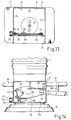
- FIGS 13 and 14 illustrate a fourth embodiment of a vacuum lift device.
- the hovering control valve 60 is slidably arranged on the inner face of the side wall 8a so that it is able to partially close the second atmospheric opening 29.
- a threaded rod 64 having an operation portion 63 and rotatably supported by support members 61, 62 is arranged on the side of the hovering control valve 60, and the threaded portion of the threaded rod 64 is screwed into a threaded bore 65 of the hovering control valve 60.
- the hovering control valve 60 moves in the axial direction of the threaded rod 64, and thereby, the opening area of the second atmospheric opening 29 is controlled.
- FIGS 15 and 16 illustrate a fifth embodiment of a vacuum lift device.
- a hovering control valve 67 pivotally supported by a support pin 66 is arranged inside of the second atmospheric opening 29 and, in addition, a threaded rod 69 equipped with an operation portion 68 is screwed into a threaded bore 70.
- An end member 71 is mounted on the tip portion of the threaded rod 69 so that it can rotate about the axis of the threaded rod 69, and this end member 71 is connected to the tip portion of the hovering control valve 67 via link members 72.
- the hovering control valve 67 is rotated about the support pin 66, and thereby, the flow area of air flowing from the second atmospheric opening 29 is controlled.
- FIGS 17 and 18 illustrate a sixth embodiment of a vacuum lift device.
- a hovering control valve 74 pivotally supported by a support pin 73 is arranged inside of the second atmospheric opening 29, and a link member 75 is pivotally connected to the tip portion of the hovering control valve 74.
- the threaded tip portion of a threaded rod 77 equipped with an operation portion 76 is screwed into a threaded bore 78 of the link member 75.
- the hovering control valve 74 is rotated about the support pin 73, and thereby, the flow area of air flowing from the second atmospheric opening 29 is controlled.
Landscapes
- Engineering & Computer Science (AREA)
- Mechanical Engineering (AREA)
- Life Sciences & Earth Sciences (AREA)
- Geology (AREA)
- Structural Engineering (AREA)
- Load-Engaging Elements For Cranes (AREA)
- Manipulator (AREA)
Abstract
Description
- The present invention relates to a vacuum lift device.
- A known vacuum lift device (JP-U-62-25344 or US-A-4 412 775) comprises a vacuum operated type lift tube which is able to expand and contract in an upward and downward direction, and a lift tube expansion control valve controlling the level of vacuum in the lift tube by controlling the opening area of the atmospheric opening of the lift tube to cause the lift tube to expand and contract in an upward and downward direction. In this vacuum lift device, for example, an object to be lifted is initially sucked and held by the lower end portion of the lift tube, and then the object is lifted by contracting the lift tube by operating the lift tube expansion control valve. Then, the object thus lifted is maintained at a desired height by operating the lift tube expansion control valve. Then, the object is caused to move to another place in a state where the object is maintained at a desired height. Then, the object is lowered and placed there.
- As mentioned above, a contraction control for lifting the object, a contraction and expansion stopping control for maintaining the object at a desired height and an expansion control for lowering the object are required for the lift tube. In the known device, these three controls are carried out by using only the lift tube expansion control valve.
- In such a vacuum lift device, the lift tube expansion control valve is completely closed when the level of vacuum in the lift tube is to be made maximum, and the lift tube expansion control valve is fully opened when the level of vacuum in the lift tube is to be made minimum. In this case, the quicker the level of vacuum can be lowered the larger the opening area of the atmospheric opening, obtained when the lift tube expansion control valve is fully opened, is made. Accordingly, the opening area of the atmospheric opening, obtained when the lift tube expansion control valve is fully open, is normally made relatively large. Namely, to quickly expand and contract the lift tube, the control range of the opening area by the lift tube expansion control valve is normally made considerably wide, and therefore, if the lift tube expansion control valve is slightly displaced, the opening area of the atmospheric opening changes considerably.
- However, to maintain the object at a desired height, the level of vacuum in the lift tube must be maintained at a constant level corresponding to the weight of the object. Namely, in this case, if the level of vacuum in the vacuum lift becomes slightly higher than this constant level, the lift tube contracts and, if the level of vacuum in the vacuum lift becomes slightly lower than this constant level, the lift tube expands. That is, to maintain the object at a desired height, the precise control of the opening area of the atmospheric opening is required.
- However, in the known vacuum lift device, as mentioned above, if the lift tube expansion control valve is slightly displaced, the opening area of the atmospheric opening changes considerably, and thus it is difficult to carry out the precise control of the opening area of the atmospheric opening by the lift tube expansion control valve. Accordingly, a problem arises in that, if the opening area of the atmospheric opening is controlled by the lift tube expansion control valve so as to maintain the object at a desired height as in this known vacuum lift device, it is difficult to properly maintain the object at a desired height.
- An object of the present invention is to provide a vacuum lift device capable of property maintaining an object lifted by the vacuum lift to a desired hight.
- To solve the above problem, according to the present invention, in a vacuum lifting device comprising a vacuum operated type lift tube which is able to expand and contract in an upward and downward direction, and a lift tube expansion control valve controlling the level of vacuum in the lift tube by controlling the opening area of the atmospheric opening of the lift tube to cause the lift tube to expand and contract in an upward and downward direction, a hovering control valve controlling the flow area between the outside space and the interior of the lift tube to maintain an object lifted by the lift tube at a desired height is provided separately from the lift tube expansion control valve.
- The expansion and contraction control of the lift tube is carried out by the lift tube expansion control valve which is capable of greatly changing the opening area of the atmospheric opening, and the expansion and contraction stopping control of the lift tube for maintaining the object at a desired height is carried out by the hovering control valve which is capable of carrying out the precise control of the flow area between the outside space and the interior of the lift tube.
- Preferably the two atmospheric openings can be completely closed by the control valve. Further the vacuum lift device comprises spring means for maintaining the control valve at a stable position in which the first atmospheric opening is closed by the lift tube control valve and in which the second atmospheric opening is open when said lift tube control valve is in a free state.
- In another embodiment of the vacuum lift device the lift tube has a flat side wall on which the first atmospheric opening and the second atmospheric opening are formed, and the first atmospheric opening is spaced from the second atmospheric opening via a band-like side wall portion, the lift tube control valve being pivotally supported by a pivot on the lift tube and having a valve plate which is slidable on the flat side wall, a lower edge of the valve plate being positioned in the band-like side wall portion when the lift tube control valve is in the free state. The lift tube control valve has a spring retainer on the atmospheric openings side with respect to the pivot, and the spring means comprises a tension spring extending from the spring retainer in a direction opposite to the pivot, one end of the tension spring being supported by the spring retainer, the other end of the tension spring being supported by the lift tube. The lift tube control valve has a spring retainer on the atmospheric openings side with respect to the pivot, and the spring means comprises a spring rod extending from the spring retainer toward the pivot side, one end of the spring rod being supported by the spring retainer, the other end of the spring rod being fixed to the lift tube. The spring retainer comprises a pair of spaced support pins, and the one end of the spring rod is inserted between the support pins. Or the spring retainer comprises a support pin having a slot formed thereon, and the one end of the spring rod is inserted into the slot. Or the spring rod has a wound portion at an intermediate portion thereof, and the wound portion is fitted around the pivot.
- The lift tube control valve has a roller roling on the side wall and rotatably supported by an end portion of the lift tube control valve, which is located furthest from the pivot, to slightly float the lift tube control valve from the side wall.
- The atmospheric opening comprises a first atmospheric opening and a second atmospheric opening, and the hovering control means controls a flow area of an air flowing within the second atmospheric opening. The hovering control means comprises an air flow passage formed between the interior of the lift tube and the second atmospheric opening, and a rotary valve having a threaded portion which projects into and retracts from the air flow passage. The hovering control means directly cooperates with the second atmospheric opening to control the flow area of an air flowing within the second atmospheric opening. The hovering control means comprises a slide valve which is able to control an opening area of the second atmospheric opening. The hovering control means comprises a manually operated rotary operation portion arranged outside of the lift tube, and a mechanism for changing the rotation of the operation portion to the sliding movement of the slide valve.
- Or the hovering control means comprises a valve plate pivotally supported by the lift tube and arranged to cover the second atmospheric opening. The hovering control means comprises a manually operated rotary operation portion arranged outside of the lift tube, and a mechanism for changing the rotation of the operation portion to the pivotal movement of the valve plate.
- Since the opening area of the atmospheric opening can be greatly changed by the lift tube expansion control valve, it is possible to quickly contract and expand the lift tube. In addition, since the level of vacuum in the lift tube can be precisely controlled by the hovering control valve, it is possible to properly maintain the object at a desired height.
- Preferably the control valve is a pivotable valve plate slideable in the flow areas of the opening and the opening. At this embodiment the valve plate is pivotable mounted on a support shaft and is fixed to a tension spring with its projecting end. In a further improvement the tension spring is mounted substantially in a radial direction with reference to the support shaft of the valve plate.
- At another embodiment the valve plate is pivotally mounted on a support shaft and is held in a resting position by means of a leave spring extending substantially parallel to the longitudinal axis of the valve plate. Thereby the end of the leave spring mounted to the valve plate is held between to opposed rollers.
- Another embodiment shows that the valve plate is pivotally mounted on a support shaft and a spiral spring is mounted on this shaft, wherein one arm of this spiral spring is fixed to the valve plate and the other arm is fixed to the suction controll apparatus, such that the control valve is held in a resting position by means of the spiral spring.
- The present invention may be more fully understood from the description of preferred embodiments of the invention set forth below, together with the accompanying drawings and the subclaims. In the drawings
- Fig. 1
- is a general view of a vacuum lift device;
- Fig. 2
- is a cross-sectional side view of the suction control apparatus;
- Fig. 3
- is a plan view of the suction control apparatus;
- Fig. 4
- is a side view of the suction control apparatus;
- Fig. 5
- is a cross-sectional plan view taken along the line V-V in Fig. 4;
- Fig. 6
- is a side view of the suction control device with the spring retainer and the tension spring being removed;
- Fig. 7
- is a cross-sectional plan view taken along the line VII-VII in Fig. 4;
- Fig. 8
- is a cross-sectional side view taken along the line VIII-VIII in Fig. 7;
- Fig. 9
- is a side view of the suction control apparatus of a second embodiment;
- Fig. 10
- is a cross-sectional plan view of the suction control apparatus shown in Fig. 9;
- Fig. 11
- is a side view of the suction control apparatus of a third embodiment;
- Fig. 12
- is a cross-sectional plan view of the suction control apparatus shown in Fig. 11;
- Fig. 13
- is a cross-sectional plan view of the suction control apparatus of a fourth embodiment;
- Fig. 14
- is a side view of the suction control apparatus shown in Fig. 13;
- Fig. 15
- is a cross-sectional plan view of the suction control apparatus of a fifth embodiment;
- Fig. 16
- is a side view of the suction control apparatus shown in Fig. 15;
- Fig. 17
- is a cross-sectional plan view of the suction control apparatus of a sixth embodiment; and
- Fig. 18
- is a side view of the suction control apparatus shown in Fig. 17.
- Referring to Figure 1, a vacuum lift device comprises a
lift tube 1 made of a flexible material and expandable in the axial direction thereof, i.e., in an upward and downward direction, acylindrical casing 2 attached to the upper end portion of thelift tube 1, and asuction control apparatus 3 attached to the lower end portion of thelift tube 1. Thecylindrical casing 2 is hung on asupport member 4 fixed to a support beam or supported by the support beam so that it is able to move in the horizontal direction. Thesuction control apparatus 3 has at its lower end asuction pad 6 for sucking and holding anobject 5 to be lifted. The interior of thelift tube 1 is connected to the suction pump (not shown) via a conduit 7, and air in thelift tube 1 is continuously sucked by this suction pump. Accordingly, vacuum is normally produced in thelift tube 1. - Referring to Figures 2 through 5, the
suction control apparatus 3 comprises fourside walls bottom wall 9, aflange portion 10 extending inward from the upper ends of theside walls cylindrical portion 11 fixed onto theflange portion 10. The lower end portion of thelift tube 1 is fixed to the outer circumferential wall of thecylindrical portion 11 in an air tight manner. Accordingly, theinterior chamber 13 of thesuction control apparatus 3, which is surrounded by theside walls cylindrical portion 11 and thebottom wall 9, is in communication with the interior of thelift tube 1, and accordingly, vacuum is produced normally in theinterior chamber 13. -
Grip portions side walls opening 16 having a circular shape is formed on thebottom wall 9 and covered by a pair ofdisc plates opening 16. Thesedisc plates rod 19 which extends upward in theinterior chamber 13. The upper portion of therod 19 is supported byrod guide members 20 fixed to theflange portion 10 so that therod 19 is able to move in the axial direction thereof. Therod 19 is biased downward by acompression spring 21 which is inserted around therod 19, and thus, a pair of thedisc plates bottom wall 9 due to the spacing force of thecompression spring 21. Accordingly, theopening 16 is normally closed by a pair of thedisc plates - The pair of the
disc plates rod 19 so that they are able to relatively rotate about therod 19, and thesedisc plates pin 23 fixed to thedisc plate 18 and projecting downward through aslot 22 formed on thedisc plate 17. A plurality of throughholes disc plates holes disc plates - As can be seen from Figs. 4 and 5, a
frame 26 having a rectangular shape projects in a transverse direction from the outer peripheral edge of theside wall 8a, and thus the outer side face of theside wall 8a is such that it is surrounded by theframe 26. A firstatmospheric opening 28 having a large area and a secondatmospheric opening 29 having a small area, which openings are spaced via a band-likeside wall portion 27, are formed on theside wall 8a, and a lift tubeexpansion control valve 30 for controlling the opening areas of theseatmospheric openings frame 26. This lift tubeexpansion control valve 30 comprises aflat valve plate 31 movable along the outer face of theside wall 8a, and alever 32 supporting thevalve plate 31. Thelever 32 is rotatably mounted on asupport shaft 34 via a radial bearing 33. In addition, thislever 32 is supported by anut 36 via athrust bearing 35. Thelever 32 extends through theframe 26 and projects outward therefrom, and anoperation arm 37 having a U shape is fixed to the projecting portion of thelever 32. The end portion of theoperation arm 37 is supported on theside wall 8c via apivot pin 38 which is arranged coaxially with thesupport shaft 34. In addition, theoperation arm 37 has anotheroperation arm 39 extending upward therefrom. Thelever 32 and thevalve plate 31 are rotated about thesupport shaft 34 by operating one of theoperation arms - A
spring retainer 40 projecting outward is fixed to the inner end portion of thelever 32, and anotherspring retainer 41 is fixed to theframe 26 located on an opposite side of thesupport shaft 34 with respect to thespring retainer 40. Atension spring 42 is arranged between thesespring retainers lever 32 is normally maintained at a position such that thespring retainers support shaft 34 are located on a straight line due to the spring force of thetension spring 42, as illustrated in Fig. 4. The position of thespring retainer 41 is determined so that the lower edge of thevalve plate 31 is located half way on the height of the band-likeside wall portion 27 when thespring retainers support shaft 34 are located on the straight line. In addition, the firstatmospheric opening 28 is formed at a position such that it is completely covered by thevalve plate 31 when thespring retainers support shaft 34 are located on the straight line. If thevalve plate 31 is caused to rotate in a clock wise direction against the spring force of thetension spring 42 by operating theoperation arms atmospheric opening 28 is caused to be open to the outside space. Conversely, if thevalve plate 31 is caused to rotate in a counter-clockwise direction against the spring force of thetension spring 42 by operating theoperation arms atmospheric opening 29 is also covered by thevalve plate 31 in addition to the firstatmospheric opening 28. The secondatmospheric opening 29 is formed at a position such that it can be completely covered by thevalve plate 31 when thevalve plate 31 is rotated in a counter-clockwise direction. - Figure 6 illustrates the case where the
spring retainer 41 and thetension spring 42 are removed. Referring to Figs. 4 through 6, aroller support plate 44 is fixed to thevalve plate 31 viaspacers 45, and a pair ofrollers 43 each rolling on the outer face of theside wall 8a are rotatably supported by theroller support plate 44. Thevalve plate 31 is slightly floated from the outer wall of theside wall 8a by therollers 43. Since thevalve plate 31 is slightly floated from the outer face of theside wall 8a as mentioned above; the inner tip end of thevalve plate 31 is supported on the outer face of theside wall 8a via therollers 43; and thelever 32 is supported by thesupport shaft 34 via the radial bearing 33 and thethrust bearing 35, it is possible to rotate the lift tubeexpansion control valve 30 with an extremely small operation power. - Referring to Figures 7 and 8, a
block 46 is arranged on the inner face of theside wall 8a so as to cover the secondatmospheric opening 29, and a connectingbore 47 interconnecting the secondatmospheric opening 29 to theinterior chamber 13 is formed in theblock 46. A hoveringcontrol valve 48 which is able to project into and retract from the connectingbore 47 is arranged in the connectingbore 47. In the embodiment illustrated in Figs. 7 and 8, the hoveringcontrol valve 48 has a bolt-like shape. Namely, inner threads engaging with the outer threads of the hoveringcontrol valve 48 are formed in theblock 46 and, if the hoveringcontrol valve 48 is rotated, the hoveringcontrol valve 48 is caused to move in the axial direction thereof. The connecting bore 47 has a height which is almost the same as the reduced diameter portion of the inner threads formed in theblock 46, and accordingly, if the tip portion of the hoveringcontrol valve 48 projects into the connectingbore 47, the flow area of the connectingbore 47 is reduced by an amount corresponding to the projecting part of the hoveringcontrol valve 48. Therefore, it is possible to control the flow area of the connectingbore 47 by rotating the hoveringcontrol valve 48. The hoveringcontrol valve 48 projects outward from theside wall 8d, and anoperation portion 49 is formed on the projecting tip portion of the hoveringcontrol valve 48. Acompression spring 50 is inserted between theoperation portion 49 and theside wall 8d to prevent the position of the hoveringcontrol valve 48 from deviating from a regular position. - When the
lift tube 1 is to be expanded to suck an object, the lift tubeexpansion control valve 30 is rotated in a clockwise direction to cause the firstatmospheric opening 28 to be open to the outside space. If the firstatmospheric opening 28 is open to the outside space, since a large amount of air flows into theinterior chamber 13 from the firstatmospheric opening 28, the level of vacuum in thelift tube 1 rapidly becomes low, and thus thelift tube 1 is expanded due to the weight of thesuction control apparatus 3. After this, when thesuction pad 6 is seated on theobject 5, the lift tubeexpansion control valve 30 is made to be in a free state, i.e., the lift tubeexpansion control valve 30 is returned to the position illustrated in Fig. 4, and thus the firstatmospheric opening 28 is covered by the lift tubeexpansion control valve 30. As a result, the level of vacuum in thelift tube 1 becomes high again. - When the
suction pad 6 is seated on theobject 5, air in thesuction pad 6 is sucked into theinterior chamber 13 via the throughholes disc plates suction pad 6, theobject 5 is sucked and held by thesuction pad 6. In this case, where theobject 5 is made of material in which air easily penetrates, since air penetrates theobject 5 and is fed into thesuction pad 6, the level of vacuum in thesuction pad 6 does not become sufficiently high, resulting in that theobject 5 can not be sucked by thesuction pad 6. - In this case, an adopter 51 illustrated by the broken line in Fig. 2 is screwed into the lower end of the
rod 19. If the adopter 51 is attached to therod 19, when thesuction pad 6 is seated on theobject 5, the adopter 51 and therod 19 are caused to move upward against the spring force of thecompression spring 21 by theobject 5. As a result, since thedisc plates suction pad 6 and theinterior chamber 13 are in communication with each other via a large clearance formed between thebottom wall 9 and the periphery of thedisc plates suction pad 6 via theobject 5, a great vacuum is produced in thesuction pad 6, and thus, theobject 5 can be sucked and held by thesuction pad 6. Note that, when thesuction pad 5 is seated on theobject 5, if the lift tubeexpansion control valve 30 is operated to temporarily cover the secondatmospheric opening 29 so that the level of vacuum in theinterior chamber 13 temporarily becomes high, theobject 5 can be instantaneously sucked and held by thesuction pad 6. - Then, if both the first
atmospheric opening 28 and the secondatmospheric opening 29 are covered by the lift tubeexpansion control valve 30 by rotating the lift tubeexpansion control valve 30 in a counter clockwise direction, the level of vacuum in thelift tube 1 rapidly becomes high. As a result, thelift tube 1 contracts, and theobject 5 is lifted by thelift tube 1. Where theobject 5 which has been lifted is to be lowered, the firstatmospheric opening 28 is caused to be open to the outside space by rotating the lift tubeexpansion control valve 30 in a clockwise direction to lower the level of vacuum in thelift tube 1. When theobject 5 is to be taken off from thesuction pad 6, the opening area of the firstatmospheric opening 28 is further increased to further lower the level of vacuum in thesuction pad 6. - Next, a control for maintaining the
suction control apparatus 3 at a desired height, i.e., a hovering control will be described. This hovering control comprises controls of two types, i.e., a hovering control for maintaining thesuction control apparatus 3 at a desired height in state where theobject 5 is lifted, and a hovering control for maintaining thesuction control apparatus 3 at a desired height in a no-load state wherein theobject 5 is not lifted. First, the former hovering control will be described. - When the hovering control is carried out, the
operation arms expansion control valve 30 is in the position illustrated in Fig. 4. Accordingly, at this time, the outside air is continuously fed into theinterior chamber 13 via the secondatmospheric opening 29. To maintain thesuction control device 3 and theobject 3 at a desired position, the upward force acting on thelift tube 1 by vacuum must be balanced with the downward force caused by the weight of thesuction control device 3 and theobject 5, and therefore, at this time, the level of vacuum to be produced in thelift tube 1 changes in accordance with the weight of theobject 5. In addition, at this time, the level of vacuum to be produced in thelift tube 1 also changes in accordance with whether or not air penetrates theobject 5. Namely, the level of vacuum to be produced in thelift tube 1 changes in accordance with theobject 5. - To maintain the
suction control apparatus 3 and theobject 5 at a desired height, initially, thelift tube 1 is slightly contracted in a state where theobject 5 is sucked and held by thesuction pad 6. Then, the operator's hand is released from theoperation arms operation arms control valve 48 is adjusted so that thelift tube 1 neither contracts nor expands. The hoveringcontrol valve 48 makes it possible to precisely control the opening area of the connectingbore 47, and thus, it is possible to control the opening area of the connectingbore 47 so that thelift tube 1 completely ceases to contract and expand. Once the adjustment of the hoveringcontrol valve 48 is completed, if the operator's hand is released from theoperation arms lift tube 1 is completely stopped as long as the same kind of theobject 5 is handled, and thus thesuction control apparatus 3 and theobject 5 are maintained at a desired height. - As illustrated in Fig. 4, where the lift tube
expansion control valve 30 is maintained at a stable position illustrated in Fig. 4 due to the spring force of thetension spring 42, when the operator's hand is released from theoperation arms expansion control valve 30 is returned to the stable position, the lift tubeexpansion control valve 30 is not always returned to the exactly same stable position, but slightly deviates from the regular stable position every time the lift tubeexpansion control valve 30 is returned to the stable position. However, since the lift tubeexpansion control valve 30 is arranged so that the lower edge of the lift tubeexpansion control valve 30 is positioned approximately at the middle of the band-likeside wall portion 27 when the lift tubeexpansion control valve 30 is in the stable position, even if the lift tubeexpansion control valve 30 slightly deviates from the regular stable position when the lift tubeexpansion control valve 30 is returned to the stable position, the firstatmospheric opening 28 is completed covered by the lift tubeexpansion control valve 30, and the entirety of the secondatmospheric opening 29 is open to the outside space. Accordingly, since the position of the lift tubeexpansion control valve 30, which is taken when the lift tubeexpansion control valve 30 is returned to the stable position, does not have any influence on the level of vacuum in thelift tube 1, if the operator's hand is released from theoperation arms suction control apparatus 3 and theobject 5 are properly maintained at a desired height. - Conversely, the
object 5 is not sucked and held by thesuction pad 6, and thus, to maintain only thesuction control apparatus 3 at a desired height, the level of vacuum in thelift tube 1 must be lowered as compared with the case where both thesuction control apparatus 3 and theobject 5 are maintained at a desired height. In this case, the level of vacuum in thelift tube 1 is adjusted by relatively rotating thedisc plates holes - Figures 9 and 10 illustrate a second embodiment of a vacuum lift device. In this second embodiment, a
support plate 53 equipped with asupport pin 52 is fixed to theside wall 8a, and one of the ends of a straightly extendingspring rod 54 is supported by thesupport pin 52. A pair of spaced support pins 55, 56 are mounted on the lift tubeexpansion control valve 30, and the tip portion of thespring rod 54 is inserted between the support pins 55, 56. When theoperation arms expansion control valve 30 is rotated about thesupport shaft 34 against the spring force of thespring rod 54. Conversely, when no external force acts on theoperation arms expansion control valve 30 is positioned about half way on the height of the band-likeside wall portion 27. - Figures 11 and 12 illustrate a third embodiment of a vacuum lift device. In this third embodiment, the
spring rod 54 has awound portion 57 in which thespring rod 54 is wound in a coil shape, and thiswound portion 57 is inserted around thesupport shaft 34. One of the ends of thespring rod 54 is fixed to thesupport pin 52, and the other end of thespring rod 54 is inserted into theslot 59 of thesupport pin 58 firmly mounted on the lift tubeexpansion control valve 30. Also in this third embodiment, when theoperation arms expansion control valve 30 is rotated about thesupport shaft 34 against the spring force of thespring rod 54 and, when no external force acts on theoperation arms expansion control valve 30 is positioned about half way on the height of the band-likeside wall portion 27. - Figures 13 and 14 illustrate a fourth embodiment of a vacuum lift device. In this fourth embodiment, the hovering
control valve 60 is slidably arranged on the inner face of theside wall 8a so that it is able to partially close the secondatmospheric opening 29. A threadedrod 64 having anoperation portion 63 and rotatably supported bysupport members control valve 60, and the threaded portion of the threadedrod 64 is screwed into a threadedbore 65 of the hoveringcontrol valve 60. When theoperation portion 63 is rotated, the hoveringcontrol valve 60 moves in the axial direction of the threadedrod 64, and thereby, the opening area of the secondatmospheric opening 29 is controlled. - Figures 15 and 16 illustrate a fifth embodiment of a vacuum lift device. In this fifth embodiment, a hovering
control valve 67 pivotally supported by asupport pin 66 is arranged inside of the secondatmospheric opening 29 and, in addition, a threadedrod 69 equipped with anoperation portion 68 is screwed into a threadedbore 70. Anend member 71 is mounted on the tip portion of the threadedrod 69 so that it can rotate about the axis of the threadedrod 69, and thisend member 71 is connected to the tip portion of the hoveringcontrol valve 67 vialink members 72. When theoperation portion 68 is rotated, the hoveringcontrol valve 67 is rotated about thesupport pin 66, and thereby, the flow area of air flowing from the secondatmospheric opening 29 is controlled. - Figures 17 and 18 illustrate a sixth embodiment of a vacuum lift device. In this sixth embodiment, a hovering
control valve 74 pivotally supported by asupport pin 73 is arranged inside of the secondatmospheric opening 29, and alink member 75 is pivotally connected to the tip portion of the hoveringcontrol valve 74. The threaded tip portion of a threadedrod 77 equipped with anoperation portion 76 is screwed into a threadedbore 78 of thelink member 75. When theoperation portion 76 is rotated, the hoveringcontrol valve 74 is rotated about thesupport pin 73, and thereby, the flow area of air flowing from the secondatmospheric opening 29 is controlled.
Claims (10)
- A vacuum lift device comprising a vacuum operated type lift tube (1) which is able to expand and contract in an upward and downward direction, and a lift tube expansion control valve (30) controlling the level of vacuum in the lift tube (1) by controlling the opening area of the atmospheric opening of the lift tube (1) to cause the lift tube (1) to expand and contract in an upward and downward direction, characterised in that a hovering control valve (48) controlling the flow area between the outside space and the interior of the lift tube (1) to maintain an object (5) lifted by the lift tube (1) at a desired height is provided separately from said lift tube expansion control valve (30).
- A vacuum lift device according to claim 1, wherein said atmospheric opening comprises a first atmospheric opening and as second atmospheric opening, and opening areas of both said first atmospheric opening and said second atmospheric opening (28 and 29) can be controlled by said control valve (30) and/or their flow areas are changeable independently.
- A vacuum lift device according to claim 1 or 2, wherein the control valve (48) is a threaded bolt screwable in the flow area of the opening (29).
- A vacuum lift device according to claim 1 or 2, wherein the control valve (60) is a valve plate slideable in the flow area of the opening (29).
- A vacuum lift device according to claim 1 or 2, wherein the control valve (67) is pivotally supported to open or close the flow area of the opening (29).
- A vacuum lift device according to claim 5, wherein the valve (67) is pivotable in the direction of the opening (29).
- A vacuum lift device according to claim 5 or 6, wherein valve (67) is driven by means of an elbow lever.
- A vacuum lift device according to one of claims 4 to 7, wherein the control valve (48, 60 or 67) is driven by means of a screw mechanism, such as a driving spindle.
- A vacuum lift device according to any of the preceeding claims, wherein the control valve (30) is held in a preferable adjustable resting position by means of a tension spring (42), a spring rod (54), a wound spring rod (54) or the like.
- A vacuum lift device according to any of the preceeding claims, wherein the control valve (48) closes the opening (28) and maintains the opening (29) completely open in its resting position.
Applications Claiming Priority (4)
| Application Number | Priority Date | Filing Date | Title |
|---|---|---|---|
| JP265099/92 | 1992-10-02 | ||
| JP26509992 | 1992-10-02 | ||
| JP5209484A JP2826045B2 (en) | 1992-10-02 | 1993-08-24 | Vacuum lift device |
| JP209484/93 | 1993-08-24 |
Publications (2)
| Publication Number | Publication Date |
|---|---|
| EP0590554A1 EP0590554A1 (en) | 1994-04-06 |
| EP0590554B1 true EP0590554B1 (en) | 1996-03-27 |
Family
ID=26517482
Family Applications (1)
| Application Number | Title | Priority Date | Filing Date |
|---|---|---|---|
| EP93115517A Expired - Lifetime EP0590554B1 (en) | 1992-10-02 | 1993-09-25 | Vacuum lift device |
Country Status (5)
| Country | Link |
|---|---|
| US (1) | US5431469A (en) |
| EP (1) | EP0590554B1 (en) |
| JP (1) | JP2826045B2 (en) |
| AT (1) | ATE136004T1 (en) |
| DE (1) | DE69301992T2 (en) |
Families Citing this family (27)
| Publication number | Priority date | Publication date | Assignee | Title |
|---|---|---|---|---|
| JPH07315796A (en) * | 1994-05-27 | 1995-12-05 | Towa Metsukusu Kk | Load handling device |
| SE506243C2 (en) * | 1996-03-29 | 1997-11-24 | Initio Ab | Vacuum lifting device where the suction capacity of the vacuum source is controlled |
| DE19614479C1 (en) * | 1996-04-12 | 1997-07-24 | Schmalz J Gmbh | Vacuum-operated manipulator |
| DE19744190C2 (en) * | 1997-09-30 | 2000-08-03 | Schmalz J Gmbh | Vacuum handling device |
| US6102459A (en) * | 1998-03-16 | 2000-08-15 | Pabst; William V. | Vacuum valve |
| DE19817777C1 (en) * | 1998-04-21 | 1999-09-09 | Schmalz J Gmbh | Suction handling head for flat panels |
| DE19817754C1 (en) * | 1998-04-21 | 1999-08-26 | Schmalz J Gmbh | Suction gripper for handling articles |
| DE19928734B4 (en) * | 1998-04-21 | 2007-08-23 | J. Schmalz Kg | Vacuum handling device |
| WO2000023362A1 (en) * | 1998-10-20 | 2000-04-27 | Koninklijke Philips Electronics N.V. | Vacuum cup |
| EP1393355A2 (en) * | 2001-05-18 | 2004-03-03 | Mattson Thermal Products GmbH | Device for receiving plate-shaped objects and device for handling said objects |
| GB0122414D0 (en) * | 2001-09-18 | 2001-11-07 | Sinclair Int Ltd | An improved applicator for labelling apparatus |
| US20060102363A1 (en) * | 2004-11-15 | 2006-05-18 | Michael Tvetene | Sod handler |
| SE530264C2 (en) * | 2006-08-23 | 2008-04-15 | Pronomic Ab | Vacuum lifting device for lifting and handling objects |
| US9303403B2 (en) * | 2009-06-26 | 2016-04-05 | Joel W. Bolin | Composite panels and methods and apparatus for manufacture and installtion thereof |
| US9061868B1 (en) | 2012-07-19 | 2015-06-23 | Wepco., Inc. | Vacuum-assisted carton or box lifter |
| SE536975C2 (en) * | 2013-05-22 | 2014-11-18 | Vaculex Ab | Vacuum tube lifting device and lifting hose and method for controlling a vacuum tube lifting device |
| US9950907B2 (en) | 2013-10-09 | 2018-04-24 | Columbia Insurance Company | Lifting methods, assemblies and systems |
| DE102015202603A1 (en) | 2015-02-12 | 2016-08-18 | J. Schmalz Gmbh | Vacuum generating device and tube lifter with a vacuum generating device |
| DE202016104731U1 (en) | 2016-08-29 | 2016-09-16 | J. Schmalz Gmbh | Vacuum handling device |
| DE102017113305A1 (en) | 2017-06-16 | 2018-12-20 | WIMAG GmbH | Vacuum lifter and suction plate |
| DE202018100403U1 (en) * | 2018-01-24 | 2019-04-25 | J. Schmalz Gmbh | Operating device for a tube lifter and tube lifter |
| DE102018105606A1 (en) * | 2018-03-12 | 2019-09-12 | J. Schmalz Gmbh | Operating device for a tube lifter and tube lifter |
| TWI656082B (en) * | 2018-06-11 | 2019-04-11 | 旭騰股份有限公司 | Electric suction cup |
| JP7180242B2 (en) * | 2018-09-26 | 2022-11-30 | 株式会社島津製作所 | Sample carrier |
| DE102019103251B4 (en) * | 2019-02-11 | 2022-05-25 | Fipa Holding Gmbh | DEVICE FOR CONTROLLING THE FUNCTION OF A VACUUM LIFTING DEVICE AND VACUUM LIFTING DEVICE WITH SUCH CONTROL DEVICE |
| DE102021102572B4 (en) * | 2021-02-04 | 2023-04-27 | J. Schmalz Gmbh | tube lifter |
| DE102023117475B4 (en) * | 2023-07-03 | 2025-05-22 | J.Schmalz Gmbh | Hose lifter with control valve |
Family Cites Families (14)
| Publication number | Priority date | Publication date | Assignee | Title |
|---|---|---|---|---|
| FR1474799A (en) * | 1965-12-30 | 1967-03-31 | Bertin & Cie | Load-carrying suction cup device |
| DE1924293B2 (en) * | 1969-05-13 | 1972-01-27 | Demag Ag, 4100 Duisburg | SUCTION HEAD FOR SOLID BODY |
| CH526461A (en) * | 1971-02-10 | 1972-08-15 | Gis Ag | Vacuum lifting device |
| US4266905A (en) * | 1979-04-20 | 1981-05-12 | Board Of Regents For Education Of The State Of Rhode Island | Apparatus for acquiring workpieces from a storage bin or the like |
| SE446621B (en) * | 1980-02-04 | 1986-09-29 | Sten Andersson | Vacuum lifting device for goods or other objects |
| US4412775A (en) * | 1982-03-10 | 1983-11-01 | Multifold-International, Inc. | Vacuum assisted machine for handling articles |
| US4557659A (en) * | 1982-09-14 | 1985-12-10 | M. Scaglia S.P.A. | Device for supporting and handling loads by means of vacuum operated suction pads |
| US4720227A (en) * | 1984-04-09 | 1988-01-19 | Eberle William J | Methods of and apparatus for stacking battery plates and the like |
| JPS6225344A (en) * | 1985-07-25 | 1987-02-03 | Nec Corp | Digital signal recoding device |
| JPH0547880Y2 (en) * | 1985-07-31 | 1993-12-17 | ||
| DE3618704C1 (en) * | 1986-06-04 | 1990-06-21 | Kurt Dr Schmalz | Lifting device with a suction box |
| GB8828914D0 (en) * | 1988-12-10 | 1989-01-18 | Palamatic Handling Syst | Vacuum lifting apparatus |
| US5035456A (en) * | 1990-03-29 | 1991-07-30 | Robert Messinger | Vacuum control system for lifting systems |
| GB9100056D0 (en) * | 1991-01-03 | 1991-02-20 | Palamatic Handling Syst | Valve arrangement |
-
1993
- 1993-08-24 JP JP5209484A patent/JP2826045B2/en not_active Expired - Lifetime
- 1993-09-25 DE DE69301992T patent/DE69301992T2/en not_active Expired - Lifetime
- 1993-09-25 AT AT93115517T patent/ATE136004T1/en not_active IP Right Cessation
- 1993-09-25 EP EP93115517A patent/EP0590554B1/en not_active Expired - Lifetime
- 1993-09-29 US US08/129,280 patent/US5431469A/en not_active Expired - Fee Related
Also Published As
| Publication number | Publication date |
|---|---|
| JPH06211482A (en) | 1994-08-02 |
| DE69301992T2 (en) | 1996-08-08 |
| ATE136004T1 (en) | 1996-04-15 |
| EP0590554A1 (en) | 1994-04-06 |
| JP2826045B2 (en) | 1998-11-18 |
| DE69301992D1 (en) | 1996-05-02 |
| US5431469A (en) | 1995-07-11 |
Similar Documents
| Publication | Publication Date | Title |
|---|---|---|
| EP0590554A1 (en) | Vacuum lift device | |
| EP0281044B1 (en) | Elevating apparatus | |
| EP0396923A1 (en) | Elevating platform and conveyance method | |
| US3424488A (en) | Modified x-frame lifting apparatus | |
| US4742651A (en) | Control device for the processing pressure on lapping, honing and polishing machines | |
| WO2000045425A1 (en) | Etching system and etching chamber | |
| US5400939A (en) | Machine for breaking glass plate | |
| KR101812072B1 (en) | Conveyor belt and pulley lifting system | |
| JP3121349B2 (en) | Shock valve for vacuum lifting device | |
| US5402543A (en) | Patient support apparatus including stabilizing mechanism | |
| EP3293370B1 (en) | Roller jack for rotatably supporting an inner casing of a turbine | |
| US5649491A (en) | Tilt table | |
| JPH028799A (en) | Screw coupler | |
| KR102189322B1 (en) | Cutting device controlling the precise lifting of the saw blade based on a hydraulic cylinder | |
| EP0513514B1 (en) | Tire curing unit | |
| CN116177137A (en) | Multifunctional grain conveying equipment and use method thereof | |
| CN208530913U (en) | A kind of feel trim actuator of vacuum room cover support force | |
| CN224145982U (en) | Plastic film roll transfer device | |
| CN222906520U (en) | Raw material bin capable of controlling discharging speed | |
| CN216789716U (en) | A easily maintain equipment support for monitored control system | |
| KR20250094167A (en) | Substrate processing apparatus | |
| KR200142418Y1 (en) | Loading device of condenser coater | |
| JP2559310B2 (en) | Brush cleaning equipment | |
| KR200397740Y1 (en) | Mask aligner mounted with air bearing | |
| KR102196755B1 (en) | Maintenance unit of substrate transfer apparatus |
Legal Events
| Date | Code | Title | Description |
|---|---|---|---|
| PUAI | Public reference made under article 153(3) epc to a published international application that has entered the european phase |
Free format text: ORIGINAL CODE: 0009012 |
|
| AK | Designated contracting states |
Kind code of ref document: A1 Designated state(s): AT BE CH DE DK ES FR GB IT LI NL SE |
|
| 17P | Request for examination filed |
Effective date: 19940505 |
|
| 17Q | First examination report despatched |
Effective date: 19950717 |
|
| GRAH | Despatch of communication of intention to grant a patent |
Free format text: ORIGINAL CODE: EPIDOS IGRA |
|
| GRAA | (expected) grant |
Free format text: ORIGINAL CODE: 0009210 |
|
| AK | Designated contracting states |
Kind code of ref document: B1 Designated state(s): AT BE CH DE DK ES FR GB IT LI NL SE |
|
| PG25 | Lapsed in a contracting state [announced via postgrant information from national office to epo] |
Ref country code: IT Free format text: LAPSE BECAUSE OF FAILURE TO SUBMIT A TRANSLATION OF THE DESCRIPTION OR TO PAY THE FEE WITHIN THE PRE;WARNING: LAPSES OF ITALIAN PATENTS WITH EFFECTIVE DATE BEFORE 2007 MAY HAVE OCCURRED AT ANY TIME BEFORE 2007. THE CORRECT EFFECTIVE DATE MAY BE DIFFERENT FROM THE ONE RECORDED.SCRIBED TIME-LIMIT Effective date: 19960327 Ref country code: ES Free format text: THE PATENT HAS BEEN ANNULLED BY A DECISION OF A NATIONAL AUTHORITY Effective date: 19960327 Ref country code: DK Effective date: 19960327 Ref country code: BE Effective date: 19960327 Ref country code: AT Effective date: 19960327 |
|
| REF | Corresponds to: |
Ref document number: 136004 Country of ref document: AT Date of ref document: 19960415 Kind code of ref document: T |
|
| REF | Corresponds to: |
Ref document number: 69301992 Country of ref document: DE Date of ref document: 19960502 |
|
| REG | Reference to a national code |
Ref country code: CH Ref legal event code: NV Representative=s name: ARDIN & CIE S.A. |
|
| ET | Fr: translation filed | ||
| PLBE | No opposition filed within time limit |
Free format text: ORIGINAL CODE: 0009261 |
|
| STAA | Information on the status of an ep patent application or granted ep patent |
Free format text: STATUS: NO OPPOSITION FILED WITHIN TIME LIMIT |
|
| 26N | No opposition filed | ||
| REG | Reference to a national code |
Ref country code: GB Ref legal event code: IF02 |
|
| PGFP | Annual fee paid to national office [announced via postgrant information from national office to epo] |
Ref country code: GB Payment date: 20020902 Year of fee payment: 10 |
|
| PGFP | Annual fee paid to national office [announced via postgrant information from national office to epo] |
Ref country code: NL Payment date: 20020916 Year of fee payment: 10 Ref country code: FR Payment date: 20020916 Year of fee payment: 10 |
|
| PGFP | Annual fee paid to national office [announced via postgrant information from national office to epo] |
Ref country code: CH Payment date: 20020920 Year of fee payment: 10 Ref country code: SE Payment date: 20020920 Year of fee payment: 10 |
|
| PG25 | Lapsed in a contracting state [announced via postgrant information from national office to epo] |
Ref country code: GB Free format text: LAPSE BECAUSE OF NON-PAYMENT OF DUE FEES Effective date: 20030925 |
|
| PG25 | Lapsed in a contracting state [announced via postgrant information from national office to epo] |
Ref country code: SE Free format text: LAPSE BECAUSE OF NON-PAYMENT OF DUE FEES Effective date: 20030926 |
|
| PG25 | Lapsed in a contracting state [announced via postgrant information from national office to epo] |
Ref country code: LI Free format text: LAPSE BECAUSE OF NON-PAYMENT OF DUE FEES Effective date: 20030930 Ref country code: CH Free format text: LAPSE BECAUSE OF NON-PAYMENT OF DUE FEES Effective date: 20030930 |
|
| PG25 | Lapsed in a contracting state [announced via postgrant information from national office to epo] |
Ref country code: NL Free format text: LAPSE BECAUSE OF NON-PAYMENT OF DUE FEES Effective date: 20040401 |
|
| EUG | Se: european patent has lapsed | ||
| GBPC | Gb: european patent ceased through non-payment of renewal fee |
Effective date: 20030925 |
|
| REG | Reference to a national code |
Ref country code: CH Ref legal event code: PL |
|
| PG25 | Lapsed in a contracting state [announced via postgrant information from national office to epo] |
Ref country code: FR Free format text: LAPSE BECAUSE OF NON-PAYMENT OF DUE FEES Effective date: 20040528 |
|
| NLV4 | Nl: lapsed or anulled due to non-payment of the annual fee |
Effective date: 20040401 |
|
| REG | Reference to a national code |
Ref country code: FR Ref legal event code: ST |
|
| PGFP | Annual fee paid to national office [announced via postgrant information from national office to epo] |
Ref country code: DE Payment date: 20121121 Year of fee payment: 20 |
|
| REG | Reference to a national code |
Ref country code: DE Ref legal event code: R071 Ref document number: 69301992 Country of ref document: DE |
|
| REG | Reference to a national code |
Ref country code: DE Ref legal event code: R071 Ref document number: 69301992 Country of ref document: DE |
|
| PG25 | Lapsed in a contracting state [announced via postgrant information from national office to epo] |
Ref country code: DE Free format text: LAPSE BECAUSE OF EXPIRATION OF PROTECTION Effective date: 20130926 |