EP0589800B1 - Plastic lined dual containment piping system and method of leak detection - Google Patents
Plastic lined dual containment piping system and method of leak detection Download PDFInfo
- Publication number
- EP0589800B1 EP0589800B1 EP93402336A EP93402336A EP0589800B1 EP 0589800 B1 EP0589800 B1 EP 0589800B1 EP 93402336 A EP93402336 A EP 93402336A EP 93402336 A EP93402336 A EP 93402336A EP 0589800 B1 EP0589800 B1 EP 0589800B1
- Authority
- EP
- European Patent Office
- Prior art keywords
- fluid
- connector
- plastic
- housing
- pipe segment
- Prior art date
- Legal status (The legal status is an assumption and is not a legal conclusion. Google has not performed a legal analysis and makes no representation as to the accuracy of the status listed.)
- Expired - Lifetime
Links
Images


Classifications
-
- F—MECHANICAL ENGINEERING; LIGHTING; HEATING; WEAPONS; BLASTING
- F16—ENGINEERING ELEMENTS AND UNITS; GENERAL MEASURES FOR PRODUCING AND MAINTAINING EFFECTIVE FUNCTIONING OF MACHINES OR INSTALLATIONS; THERMAL INSULATION IN GENERAL
- F16L—PIPES; JOINTS OR FITTINGS FOR PIPES; SUPPORTS FOR PIPES, CABLES OR PROTECTIVE TUBING; MEANS FOR THERMAL INSULATION IN GENERAL
- F16L39/00—Joints or fittings for double-walled or multi-channel pipes or pipe assemblies
- F16L39/005—Joints or fittings for double-walled or multi-channel pipes or pipe assemblies for concentric pipes
-
- F—MECHANICAL ENGINEERING; LIGHTING; HEATING; WEAPONS; BLASTING
- F16—ENGINEERING ELEMENTS AND UNITS; GENERAL MEASURES FOR PRODUCING AND MAINTAINING EFFECTIVE FUNCTIONING OF MACHINES OR INSTALLATIONS; THERMAL INSULATION IN GENERAL
- F16L—PIPES; JOINTS OR FITTINGS FOR PIPES; SUPPORTS FOR PIPES, CABLES OR PROTECTIVE TUBING; MEANS FOR THERMAL INSULATION IN GENERAL
- F16L23/00—Flanged joints
- F16L23/16—Flanged joints characterised by the sealing means
- F16L23/167—Flanged joints characterised by the sealing means in connection with the appearance or detection of leaks
-
- F—MECHANICAL ENGINEERING; LIGHTING; HEATING; WEAPONS; BLASTING
- F16—ENGINEERING ELEMENTS AND UNITS; GENERAL MEASURES FOR PRODUCING AND MAINTAINING EFFECTIVE FUNCTIONING OF MACHINES OR INSTALLATIONS; THERMAL INSULATION IN GENERAL
- F16L—PIPES; JOINTS OR FITTINGS FOR PIPES; SUPPORTS FOR PIPES, CABLES OR PROTECTIVE TUBING; MEANS FOR THERMAL INSULATION IN GENERAL
- F16L58/00—Protection of pipes or pipe fittings against corrosion or incrustation
- F16L58/02—Protection of pipes or pipe fittings against corrosion or incrustation by means of internal or external coatings
- F16L58/04—Coatings characterised by the materials used
- F16L58/10—Coatings characterised by the materials used by rubber or plastics
- F16L58/1009—Coatings characterised by the materials used by rubber or plastics the coating being placed inside the pipe
-
- Y—GENERAL TAGGING OF NEW TECHNOLOGICAL DEVELOPMENTS; GENERAL TAGGING OF CROSS-SECTIONAL TECHNOLOGIES SPANNING OVER SEVERAL SECTIONS OF THE IPC; TECHNICAL SUBJECTS COVERED BY FORMER USPC CROSS-REFERENCE ART COLLECTIONS [XRACs] AND DIGESTS
- Y10—TECHNICAL SUBJECTS COVERED BY FORMER USPC
- Y10S—TECHNICAL SUBJECTS COVERED BY FORMER USPC CROSS-REFERENCE ART COLLECTIONS [XRACs] AND DIGESTS
- Y10S285/00—Pipe joints or couplings
- Y10S285/91—Gaskets
-
- Y—GENERAL TAGGING OF NEW TECHNOLOGICAL DEVELOPMENTS; GENERAL TAGGING OF CROSS-SECTIONAL TECHNOLOGIES SPANNING OVER SEVERAL SECTIONS OF THE IPC; TECHNICAL SUBJECTS COVERED BY FORMER USPC CROSS-REFERENCE ART COLLECTIONS [XRACs] AND DIGESTS
- Y10—TECHNICAL SUBJECTS COVERED BY FORMER USPC
- Y10T—TECHNICAL SUBJECTS COVERED BY FORMER US CLASSIFICATION
- Y10T29/00—Metal working
- Y10T29/49—Method of mechanical manufacture
- Y10T29/49826—Assembling or joining
- Y10T29/49863—Assembling or joining with prestressing of part
- Y10T29/4987—Elastic joining of parts
- Y10T29/49872—Confining elastic part in socket
Definitions
- the present invention relates to methods and apparatus for dual containment of piped substances.
- the invention more particularly relates to piping systems constructed of flanged concentric pipe segments and having an interior plastic liner to protect the segments from corrosive piped substances.
- the invention permits fluids, which may leak from the inner shell of a concentric or dual-walled pipe segment, to be detected before escape of the fluid into the environment.
- the invention features a connector that provides a secure and reliable seal between connected pipe segments and enables leak detection monitoring to be conducted at such connection points.
- the invention also features a novel concentric-type pipe segment design having an annulus, a flange which presents an exterior axial flanged face, and an aperture communicating the annulus with the exterior flange face. The aperture is adapted to transmit fluid which has leaked from the inner shell of the pipe segment into communication with a connector which adjoins the exterior flange face.
- a flanged pipe segment for double pipe conduits is known from US-A-1 389 768.
- This type of piping system may include a passage extending through the flange of a pipe segment, whereby leakage between flanges of abutting pipe segments may be flushed from the passage.
- Inner and outer O-ring seals on the flanges may be used to bracket the entrance to the passage along the flange face.
- Hazardous chemical piping systems also exist which employ rigid mating of adjacent components. Connectors are used which essentially transmit the entire bolt torque load from joined flanges of two pipe elements across a single metal ring. Such a system may permit higher bolt torque loads to be used in connecting the elements than other systems. However, the rigid mating of this system is vulnerable to vibration-induced fatigue and failure over time.
- the present invention features a piping system constructed of flanged concentric pipe segments having inner and outer shells and preferably lined with plastic or other non-corrosive material along their interior.
- An annulus is defined between the inner and outer shells of the pipe segments.
- an aperture is provided which communicates the annulus with the external axial flange face of the segment's flange.
- a dual containment connector is also described which is adapted to be placed between adjacent concentric pipe segments.
- the connector has at least one port along its outer circumference to permit operable connection with fluid detection devices such as are known in the art.
- the dual containment connector includes annular resilient sealing members and plastic flanges to produce a secure and reliable seal between connected pipe segments.
- the connector further comprises a housing preferably constructed of durable and fire resistant material such as steel.
- the invention provides for improved detection and prevention of leakage by providing an annular containment passageway which captures fluid escaping from the pipe's interior and allows detection before its escape into the environment.
- the annular containment passageway is formed by the annulus of at least one concentric pipe segment, at least one aperture communicating the annulus with the flange face, and an annular fluid opening within the connector.
- the annular fluid opening is adapted to engage the pipe segment's aperture, receive fluid from the aperture, and communicate it to the connector's fluid detection port.
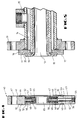
- FIGURE 1 shows a longitudinal partial cross-section of an exemplary concentric pipe segment of the present invention.
- FIGURE 2 is an end phantom detail of a flanged end of an exemplary pipe segment.
- FIGURE 3 is a side phantom detail of a flanged end of an exemplary pipe segment.
- FIGURE 4 is a side view cross-section of an exemplary connector of the present invention.
- FIGURE 5 is a side view cross-section of a flanged end of an exemplary pipe segment adapted to engage the exemplary connector of FIGURE 4.
- FIGURE 6 is a cross-sectional detail, partially in phantom, showing a connection of two pipe segments and a connector.
- Pipe segments of the present invention include conventional straight runs of piping as well as curved sections and fittings such as tees, elbows, reducers and other conventional and unconventional piping designs.
- FIG. 1 shows exemplary pipe segments 10, 30, and 35 which illustrate three of the various pipe segment configurations.
- Each illustrated segment comprises inner shell 11 and outer shell 12, each having a first and a second end.
- Both shells 11 and 12 are preferably formed of rigid, durable material such as steel or ductile cast iron.
- the segments are termed concentric in that the inner and outer shells have generally the same axial center along their lengths, the outer shell 12 having a diameter greater than that of the inner shell 11.
- Inner shell 11's inner surface defines a fluid pathway through the length of the pipe segment.
- Shells 11 and 12 are joined at their first and second ends such that a flange 16 is formed.
- Annulus 14 is defined between the inner surface of outer shell 12 and the outer surface of inner shell 11.
- the outer shell 12 of the pipe segment can include one or more connection ports 15 which are adapted to permit connection of fluid detection devices of types known in the art.
- plastic liner 13 which is typically formed of corrosion-resistant resins of types known in the art.
- plastic liner 13 comprises polytetrafluoroethylene (PTFE). Liners may also be used which are made from perfluoro alkoxyalkane (PFA), perfluoro ethylene-propylene (FEP), polyvinylidene fluoride (PVDF) and polypropylene (PP).
- PFA perfluoro alkoxyalkane
- FEP perfluoro ethylene-propylene
- PVDF polyvinylidene fluoride
- PP polypropylene
- FIG. 1 A system exemplified by that shown in FIG. 1 allows dual containment of piped substances. These substances are primarily intended to be contained within the central portion of inner shell 11 and inner plastic liner 13. In the event that liner 13 and inner shell 11 are breached, outer shell 12 provides a secondary means of containment.
- each pipe segment terminates at its ends to form a flange.
- the flanges formed at the ends of the pipe segments is further illustrated in FIGS. 2 and 3 showing flange 16 of pipe segment 10.
- inner and outer shells 11 and 12 join at their ends to form annulus 14 and an exterior flange face 17.
- Plastic liner 13 is flared at its ends along flange face 17 to provide a plastic-liner flange face 18 over a portion of flange face 17.
- the segment may be fitted with one or more lap flanges 19 to permit the segment to be fixedly connected to an adjoining segment.
- At least one aperture 20 is provided which communicates annulus 14 with flange face 17.
- the outside diameter of the plastic-liner flange face 18 is such that aperture 20 is not blocked by the plastic-liner flange.
- aperture 20 is positioned in flange face 17 such that aperture 20 will be within the inside diameter surface of annular sealing members positioned between adjacent pipe segments. Similar configurations for aperture 20 can be seen in segments 30 and 35 in FIG. 1.
- dual containment connector 40 comprises a generally annular housing 41 preferably formed of a durable, fire-resistant material such as cast iron, steel or another metal to protect the connector from external hazards such as fire or impacts.
- Housing 41 defines a central fluid pathway 65 through housing 41 to faciltate fluid flow from one adjoining pipe segment to another adjoining pipe segment.
- Housing 41 comprises an outer housing section 60 and an inner housing section 61.
- Inner housing section 61 generally includes that portion of the housing 41 which will be lined with plastic liner 45 or adjoin a plastic-lined portion of pipe segments during construction of a piping system.
- Outer housing section 60 generally corresponds to the area of the housing lying radially outside the plastic-lined sections.
- Outer housing section 60 may include holes 42 to accommodate connection bolts or pins used to connect adjoining pipe segments. As is illustrated in FIGS. 4 and 6, axial sides of connector 40 present first and second housing faces 62 and 63 which are adapted for cooperating engagement with complementary flange faces 17 of adjoining pipe segments to be connected. Plastic liner 45 lines the central fluid pathway 65 of connector 40.
- Housing 41 is fitted with first and second annular resilient sealing members 43 and 44 which are concentrically arranged upon first and second housing faces 62 and 63 and which are adapted to sealingly engage complementary flange faces 17 of adjoining concentric pipe segments to be connected.
- Sealing members 43 and 44 each present radially an inside diameter surface 70 and outside diameter surface 71.
- sealing members 43 and 44 have a spring bias to urge seals against flange faces 17 of pipe segments to be connected.
- sealing members 43 and 44 comprise spiral-wound type gaskets of a type known in the art whose cross-section resembles a series of radially aligned leaf springs which can be axially compressed during a connection of adjoining pipe segments.
- a commercially available annular resilient sealing member of this type is the Flexitallic® spiral-wound gasket with Flexicarb filler available from Flexitallic, Inc., Deer Park, TX 77536.
- the sealing members 43 and 44 can be spring-biased in other ways as well, both mechanically and hydraulically.
- Plastic liner 45 is flared at its axial ends to form first and second plastic flanges 46 and 47 upon either axial side of connector 40 which have an outside diameter which is less than the inside diameter surface of annular resilient sealing members 43 and 44.
- Plastic flanges 46 and 47 each present an interior housing face which axially faces connector 40 and an exterior plastic flange face which faces outwardly from connector 40 and is adapted to sealingly engage complementary plastic flange faces 18 of adjoining pipe segments to be connected.
- connector 40 provides for an inner seal wherein the exterior plastic flange faces of plastic flanges 46 and 47 are resiliently outwardly biased to seal against an adjoining segment's plastic lined flange faces 18 when the segments are connected to provide a secure and reliable seal.
- Rigid facings 48 and 49 and spring members 50 and 51 further ensure the seal by urging plastic flanges 46 and 47 against plastic-liner flange faces 18 while the segments are connected.
- Spring members 50 and 51 preferably comprise an annular spring member commonly referred to as a wave spring or wave spring washer. Acceptable commercially available wave springs for this application include those such as manufactured by Spring Engineers of 9740 Tanner Road, Houston, Texas 77041.
- spring members 50 and 51 are axially compressed creating both inner and outer fluid-tight seals against pipe segments being joined.
- the specific recommended bolt-torque loads used in constructing piping systems with the inventive components may vary among particular systems. Generally, however, the bolt torque loads used should be sufficient to ensure axial compression of the spring members and annular resilient sealing members without being so great as to permanently deform them or remove their spring-like characteristics.
- housing 41 is adapted to communicate fluid from either axial side of housing 41 toward a connection port 53 through annular fluid openings 52 when the pipe segments are fixedly connected by, for instance, bolt 56 (see FIG. 6).
- fluid communication is even possible from one axial side of housing 41 to the other if fluid flows from one annular fluid opening to the other across the cavity in housing 41 formed by the connection port 53.
- Annular fluid openings 52 are defined within housing 41 on either side of connector 40.
- the annular openings 52 are in fluid communication with connection port 53 and are adapted to recieve fluid from an axially external source, such as the aperture 20 of an adjoining pipe segment, and transmit said fluid toward the connection port 53.
- the radially outward boundaries of annular fluid openings 52 are generally formed by the inside diameter surface 70 of sealing members 43 and 44 during connection of connector 40 with an adjoining pipe segment.
- FIG. 6 illustrates an exemplary technique for defining the annular fluid openings 52 wherein the openings are generally defined along their outer periphery by outer housing section 60 and the inside diameter surface 70 of annular resilient sealing members 43 and 44.
- the exemplary openings 52 are further defined along their inner periphery by the outer portions of inner housing section 61, rigid facings 48 and 49, spring members 50 and 51 and plastic flanges 46 and 47.
- Connection port 53 is shown which is in fluid communication with annular openings 52.
- connection port 53 comprises a shaft 54 to receive fluid from opening 52 and communicate it to the exterior periphery of housing 41.
- Threaded connection 55 in housing 41 permits operable connection of fluid detection or monitoring devices to connector 40 thereby permitting leakage into annulus 14 and transmitted toward the connector 40 to be detected. Exemplary connections of this type are shown in FIGS. 1 and 6.
- the invention provides connected pipe segments with an annular containment passageway formed by the annulus 14 of at least one pipe segment, aperture 20, and annular fluid opening 52 of at least one connector 40.
- the establishment of an annular containment passageway permits true dual containment since reliable secondary containment may be made available at all points along a piping system, including the flanged connection points.
- Construction of a piping system in accordance with the present invention also permits improved fire safety by providing an outer seal which does not present plastic portions which may be subject to melting or degradation from fire.
- Leakage from the inner shell 11 of at least one pipe segment of the piping system may be detected and monitored from the annular containment passageway as well.
- the annular containment passageway may include any number of connected pipe segments and connectors thereby offering numerous connection ports for leak detection at the connectors. Such leak detection points may be supplemented at connection ports 15 at points along the lengths of the segments as well.
- a suitable fluid detection device for use with the piping system is a detector for the particular substance flowing through the piping system. Fluid detection and leak monitoring devices known to be useful in common application include the hazardous gas monitor alarm available from Mitchell Instrument Co., San Marcos, CA 92069.
Landscapes
- Engineering & Computer Science (AREA)
- General Engineering & Computer Science (AREA)
- Mechanical Engineering (AREA)
- Examining Or Testing Airtightness (AREA)
- Rigid Pipes And Flexible Pipes (AREA)
- Pipeline Systems (AREA)
- Flanged Joints, Insulating Joints, And Other Joints (AREA)
- Quick-Acting Or Multi-Walled Pipe Joints (AREA)
Abstract
Description
- The present invention relates to methods and apparatus for dual containment of piped substances. The invention more particularly relates to piping systems constructed of flanged concentric pipe segments and having an interior plastic liner to protect the segments from corrosive piped substances. The invention permits fluids, which may leak from the inner shell of a concentric or dual-walled pipe segment, to be detected before escape of the fluid into the environment. The invention features a connector that provides a secure and reliable seal between connected pipe segments and enables leak detection monitoring to be conducted at such connection points. The invention also features a novel concentric-type pipe segment design having an annulus, a flange which presents an exterior axial flanged face, and an aperture communicating the annulus with the exterior flange face. The aperture is adapted to transmit fluid which has leaked from the inner shell of the pipe segment into communication with a connector which adjoins the exterior flange face.
- A flanged pipe segment for double pipe conduits is known from US-A-1 389 768.
- Many facilities which handle hazardous or caustic chemicals cannot permit even tiny amounts of piped substances to escape without risking significant health or environmental consequences. Accordingly, a number of apparatuses and techniques have been suggested for containing and detecting leaks in piping systems. Some of these suggestions have involved the use of concentric pipe segments. One such suggestion, for instance as disclosed in US-A-5 141 256, features a piping system of flanged concentric pipe segments in which the segments have an interspace defined between the inner and outer segments. Leak detection fittings are positioned along outer pipe segments which permit monitoring of escaped material into the interspace. This type of piping system may include a passage extending through the flange of a pipe segment, whereby leakage between flanges of abutting pipe segments may be flushed from the passage. Inner and outer O-ring seals on the flanges may be used to bracket the entrance to the passage along the flange face.
- Hazardous chemical piping systems also exist which employ rigid mating of adjacent components. Connectors are used which essentially transmit the entire bolt torque load from joined flanges of two pipe elements across a single metal ring. Such a system may permit higher bolt torque loads to be used in connecting the elements than other systems. However, the rigid mating of this system is vulnerable to vibration-induced fatigue and failure over time.
- Although such systems facilitate control of leaks from piping system segments, they do not facilitate active monitoring of leaks at flanged connection points. In fact, it is at connection points that leakage is oftentimes most likely to occur. The escaping fluid can also breach an outer O-ring seal and thereby result in fluid reaching the environment before it can be detected. This is a distinct possibility when the fluid is especially corrosive. O-ring seals, as well as rigid matings, at connection points also tend to fail or weaken when subjected to vibration, repeated temperature changes, impacts, fire, or other hazards.
- In another background aspect it is noted that, while alternative piping systems exist which offer dual containment layers along the length of the pipe segments, these systems provide only a single acceptable fluid seal at leakage-prone flanged connection points. The absence of a second reliable seal against leaks belies such a system's claim of providing true dual containment. Clearly, systems that provide true dual containment and facilitate meaningful leak detection are desirable.
- These problems are overcome by the features of
claims - The present invention features a piping system constructed of flanged concentric pipe segments having inner and outer shells and preferably lined with plastic or other non-corrosive material along their interior. An annulus is defined between the inner and outer shells of the pipe segments. At either end of the pipe segment, an aperture is provided which communicates the annulus with the external axial flange face of the segment's flange.
- A dual containment connector is also described which is adapted to be placed between adjacent concentric pipe segments. The connector has at least one port along its outer circumference to permit operable connection with fluid detection devices such as are known in the art. The dual containment connector includes annular resilient sealing members and plastic flanges to produce a secure and reliable seal between connected pipe segments. The connector further comprises a housing preferably constructed of durable and fire resistant material such as steel.
- The invention provides for improved detection and prevention of leakage by providing an annular containment passageway which captures fluid escaping from the pipe's interior and allows detection before its escape into the environment. The annular containment passageway is formed by the annulus of at least one concentric pipe segment, at least one aperture communicating the annulus with the flange face, and an annular fluid opening within the connector. The annular fluid opening is adapted to engage the pipe segment's aperture, receive fluid from the aperture, and communicate it to the connector's fluid detection port.
- FIGURE 1 shows a longitudinal partial cross-section of an exemplary concentric pipe segment of the present invention.
- FIGURE 2 is an end phantom detail of a flanged end of an exemplary pipe segment.
- FIGURE 3 is a side phantom detail of a flanged end of an exemplary pipe segment.
- FIGURE 4 is a side view cross-section of an exemplary connector of the present invention.
- FIGURE 5 is a side view cross-section of a flanged end of an exemplary pipe segment adapted to engage the exemplary connector of FIGURE 4.
- FIGURE 6 is a cross-sectional detail, partially in phantom, showing a connection of two pipe segments and a connector.
- Pipe segments of the present invention include conventional straight runs of piping as well as curved sections and fittings such as tees, elbows, reducers and other conventional and unconventional piping designs. FIG. 1 shows
exemplary pipe segments inner shell 11 andouter shell 12, each having a first and a second end. Bothshells outer shell 12 having a diameter greater than that of theinner shell 11.Inner shell 11's inner surface defines a fluid pathway through the length of the pipe segment.Shells flange 16 is formed.Annulus 14 is defined between the inner surface ofouter shell 12 and the outer surface ofinner shell 11. Theouter shell 12 of the pipe segment can include one ormore connection ports 15 which are adapted to permit connection of fluid detection devices of types known in the art. - The interior of
inner shell 11 is lined with an innerplastic liner 13 which is typically formed of corrosion-resistant resins of types known in the art. In a preferred embodiment,plastic liner 13 comprises polytetrafluoroethylene (PTFE). Liners may also be used which are made from perfluoro alkoxyalkane (PFA), perfluoro ethylene-propylene (FEP), polyvinylidene fluoride (PVDF) and polypropylene (PP). - A system exemplified by that shown in FIG. 1 allows dual containment of piped substances. These substances are primarily intended to be contained within the central portion of
inner shell 11 and innerplastic liner 13. In the event thatliner 13 andinner shell 11 are breached,outer shell 12 provides a secondary means of containment. - As indicated, each pipe segment terminates at its ends to form a flange. The flanges formed at the ends of the pipe segments is further illustrated in FIGS. 2 and 3 showing
flange 16 ofpipe segment 10. As is further indicated, inner andouter shells annulus 14 and anexterior flange face 17.Plastic liner 13 is flared at its ends alongflange face 17 to provide a plastic-liner flange face 18 over a portion offlange face 17. In an embodiment best shown in FIG. 5, the segment may be fitted with one ormore lap flanges 19 to permit the segment to be fixedly connected to an adjoining segment. At least oneaperture 20 is provided which communicatesannulus 14 withflange face 17. As illustrated, the outside diameter of the plastic-liner flange face 18 is such thataperture 20 is not blocked by the plastic-liner flange. Moreover,aperture 20 is positioned inflange face 17 such thataperture 20 will be within the inside diameter surface of annular sealing members positioned between adjacent pipe segments. Similar configurations foraperture 20 can be seen insegments - Referring now to FIG. 4,
dual containment connector 40 comprises a generallyannular housing 41 preferably formed of a durable, fire-resistant material such as cast iron, steel or another metal to protect the connector from external hazards such as fire or impacts.Housing 41 defines acentral fluid pathway 65 throughhousing 41 to faciltate fluid flow from one adjoining pipe segment to another adjoining pipe segment.Housing 41 comprises anouter housing section 60 and aninner housing section 61.Inner housing section 61 generally includes that portion of thehousing 41 which will be lined withplastic liner 45 or adjoin a plastic-lined portion of pipe segments during construction of a piping system.Outer housing section 60 generally corresponds to the area of the housing lying radially outside the plastic-lined sections.Outer housing section 60 may includeholes 42 to accommodate connection bolts or pins used to connect adjoining pipe segments. As is illustrated in FIGS. 4 and 6, axial sides ofconnector 40 present first and second housing faces 62 and 63 which are adapted for cooperating engagement with complementary flange faces 17 of adjoining pipe segments to be connected.Plastic liner 45 lines thecentral fluid pathway 65 ofconnector 40. -
Housing 41 is fitted with first and second annularresilient sealing members Sealing members inside diameter surface 70 and outsidediameter surface 71. Preferably, sealingmembers members members -
Plastic liner 45 is flared at its axial ends to form first and secondplastic flanges connector 40 which have an outside diameter which is less than the inside diameter surface of annularresilient sealing members Plastic flanges connector 40 and an exterior plastic flange face which faces outwardly fromconnector 40 and is adapted to sealingly engage complementary plastic flange faces 18 of adjoining pipe segments to be connected. - Referring to FIGS. 4-6,
connector 40 provides for an inner seal wherein the exterior plastic flange faces ofplastic flanges Rigid facings spring members plastic flanges Spring members - Under bolt-torque compression loads,
spring members members exemplary connector 40, are axially compressed creating both inner and outer fluid-tight seals against pipe segments being joined. The specific recommended bolt-torque loads used in constructing piping systems with the inventive components may vary among particular systems. Generally, however, the bolt torque loads used should be sufficient to ensure axial compression of the spring members and annular resilient sealing members without being so great as to permanently deform them or remove their spring-like characteristics. - An outer seal is created between either of sealing
members flange face 17 to which each sealing member is mated. An inner seal is created between either ofplastic flanges liner flange face 18 to which each plastic flange is mated. Since both the inner and outer seals incorporate spring-bias means for sealing, theconnector 40 is not rigidly mated to the pipe elements on either side of it. As a result, piping systems constructed in accordance with the present invention are better suited to resist vibration-induced fatigue and failure at connection joints than piping systems constructed by a rigid mating technique. - Referring to FIG. 6, a particularly preferred embodiment is shown in which
housing 41 is adapted to communicate fluid from either axial side ofhousing 41 toward aconnection port 53 throughannular fluid openings 52 when the pipe segments are fixedly connected by, for instance, bolt 56 (see FIG. 6). As best seen in FIG. 6, fluid communication is even possible from one axial side ofhousing 41 to the other if fluid flows from one annular fluid opening to the other across the cavity inhousing 41 formed by theconnection port 53. - Annular
fluid openings 52 are defined withinhousing 41 on either side ofconnector 40. Theannular openings 52 are in fluid communication withconnection port 53 and are adapted to recieve fluid from an axially external source, such as theaperture 20 of an adjoining pipe segment, and transmit said fluid toward theconnection port 53. The radially outward boundaries ofannular fluid openings 52 are generally formed by theinside diameter surface 70 of sealingmembers connector 40 with an adjoining pipe segment. FIG. 6 illustrates an exemplary technique for defining theannular fluid openings 52 wherein the openings are generally defined along their outer periphery byouter housing section 60 and theinside diameter surface 70 of annularresilient sealing members exemplary openings 52 are further defined along their inner periphery by the outer portions ofinner housing section 61,rigid facings spring members plastic flanges -
Connection port 53 is shown which is in fluid communication withannular openings 52. In one embodiment,connection port 53 comprises ashaft 54 to receive fluid from opening 52 and communicate it to the exterior periphery ofhousing 41. Threadedconnection 55 inhousing 41 permits operable connection of fluid detection or monitoring devices toconnector 40 thereby permitting leakage intoannulus 14 and transmitted toward theconnector 40 to be detected. Exemplary connections of this type are shown in FIGS. 1 and 6. - In operation, the invention provides connected pipe segments with an annular containment passageway formed by the
annulus 14 of at least one pipe segment,aperture 20, andannular fluid opening 52 of at least oneconnector 40. The establishment of an annular containment passageway permits true dual containment since reliable secondary containment may be made available at all points along a piping system, including the flanged connection points. Construction of a piping system in accordance with the present invention also permits improved fire safety by providing an outer seal which does not present plastic portions which may be subject to melting or degradation from fire. - Leakage from the
inner shell 11 of at least one pipe segment of the piping system may be detected and monitored from the annular containment passageway as well. The annular containment passageway may include any number of connected pipe segments and connectors thereby offering numerous connection ports for leak detection at the connectors. Such leak detection points may be supplemented atconnection ports 15 at points along the lengths of the segments as well. A suitable fluid detection device for use with the piping system is a detector for the particular substance flowing through the piping system. Fluid detection and leak monitoring devices known to be useful in common application include the hazardous gas monitor alarm available from Mitchell Instrument Co., San Marcos, CA 92069. - While the invention has been described with respect to certain preferred embodiments, it should be understood that the inventive concepts disclosed herein are intented to be limited only by the following claims.
Claims (11)
- A pipe segment comprising :an inner shell (11) of a first diameter having a first end and a second end and an internal surface defining a fluid pathway through said pipe segment, an outer shell (12) of a second diameter greater than said first diameter having a first end and a second end, said inner and outer shells having generally the same axial center, said inner and outer shells defining an annulus (14) therebetween,said inner and outer shells are joined to form a flange (16) at said first and second ends of said pipe segment, said flanges presenting an exterior axial flange face (17),an aperture (20) communicates the annulus with the flange face, characterized in that :
a plastic liner (13) lines the interior of said inner shell, said plastic liner being flared at its ends along said flange faces to provide a plastic flange face (18) over at least a portion of said flange face (17). - The pipe segment of claim 1 further comprising one or more connection ports (15) along the length of said outer shell (12) said connection ports being adapted to communicate said annulus (14) with the exterior of said pipe segment and to permit connection of fluid detection devices.
- A pipe segment connector, comprising :a connector housing (41) having first and second faces (62,63) adapted for cooperating engagement with complementary flange faces of adjoining pipe segments to be connected, said connector housing further comprising a central fluid pathway (65) through said through said connector housing for facilitating fluid flow from one adjoining pipe segment to another adjoining pipe segment,first and second annular resilient sealing members (43,44) concentrically arranged on said first and second housing faces (62,63) around said central fluid pathway, said sealing members having an outside diameter surface (71) and an inside diameter surface (70) and being adapted to sealingly engage complementary flange faces (17) of adjoining pipe segments to be connected, a port (53) formed in the exterior of said housing and adapted for attachment to a fluid detection device,characterized in that it comprises :a plastic liner (45) lining said central fluid pathway (65), said plastic liner being flared at its ends to form first and second plastic flanges (46,47), having an exterior flange face and an interior housing face, said plastic flanges having an outside diameter measuring less than said inside diameter surface of said annular resilient sealing members, said exterior plastic flange faces being adapted to sealingly engage complementary plastic flange faces (18) of adjoining pipe segments to be connected, andmeans (48, 49 ; 50,51) for resiliently outwardly biasing said plastic flanges.
- The connector of claim 3 wherein the connector comprises one or more annular fluid openings (52) within said housing, said annular fluid openings being in fluid communication with said port (53) and adapted to receive fluid from an axially external source and transmit said fluid toward said port.
- The connector of claim 3 wherein the connector comprises an inner seal whereby said plastic flanges are outwardly resiliently biased using one or more spring members (50,51) to provide sealing against plastic-liner flange faces (18) of connected concentric pipe segments.
- The connector of claim 3 wherein said annular resilient members (43,44) are spring-biased to urge sealing against flange faces (17) of connected concentric pipe segments.
- The connector of claim 3 wherein said housing (41) is made of fire-resistant material.
- The connector of claim 3 wherein said port (53) comprises a threaded connection (55) within said housing to permit operable connection of fluid detection devices with said connector.
- A piping system for permitting dual containment and detection of leaks of piped substances, said piping system comprising at least one pipe segment as claimed in claim 1 or claim 2 and at least one connector as claimed in any one of claims 3 to 8.
- A method for detecting leaks of piped substances from a piping system comprising the steps of :a. using a piping system as claimed in claim 9.b. operably connecting a fluid detection device to the port (53) within the housing (41) of at least one connector (40) of said piping system to assist in detection of a leak of fluid from the inner shell (11) of at least one said pipe segments (10,30,35) into the annulus (14) of said pipe segment, andc. permitting said leak of fluid to be detected by said fluid detection means by allowing fluid within said annulus to be communicated through one or more said apertures (20) into said annular fluid opening of one or more said connectors and through said port within said connector's housing toward said fluid detection means.
- A method of monitoring the containment of piped substances, comprising :a. detecting leaks of piped substances from the piping system by the method of claim 10 using a fluid detection device,b. monitoring said fluid detection device.
Applications Claiming Priority (2)
| Application Number | Priority Date | Filing Date | Title |
|---|---|---|---|
| US07/951,215 US5277455A (en) | 1992-09-25 | 1992-09-25 | Plastic lined dual containment piping system |
| US951215 | 1992-09-25 |
Publications (2)
| Publication Number | Publication Date |
|---|---|
| EP0589800A1 EP0589800A1 (en) | 1994-03-30 |
| EP0589800B1 true EP0589800B1 (en) | 1997-06-11 |
Family
ID=25491430
Family Applications (1)
| Application Number | Title | Priority Date | Filing Date |
|---|---|---|---|
| EP93402336A Expired - Lifetime EP0589800B1 (en) | 1992-09-25 | 1993-09-24 | Plastic lined dual containment piping system and method of leak detection |
Country Status (8)
| Country | Link |
|---|---|
| US (1) | US5277455A (en) |
| EP (1) | EP0589800B1 (en) |
| JP (1) | JPH06235492A (en) |
| AT (1) | ATE154422T1 (en) |
| DE (1) | DE69311480T2 (en) |
| DK (1) | DK0589800T3 (en) |
| ES (1) | ES2105168T3 (en) |
| GR (1) | GR3024680T3 (en) |
Cited By (1)
| Publication number | Priority date | Publication date | Assignee | Title |
|---|---|---|---|---|
| EP4217643A4 (en) * | 2020-09-24 | 2024-10-09 | Trinity Bay Equipment Holdings, LLC | PIPE BREACH DETECTION SYSTEMS AND METHODS FOR BORE AND ANNULAR GAP MONITORING |
Families Citing this family (42)
| Publication number | Priority date | Publication date | Assignee | Title |
|---|---|---|---|---|
| US5564715A (en) * | 1993-10-15 | 1996-10-15 | Corrosion Control Corp. | Tandem seal device for flow line applications |
| US5390532A (en) * | 1993-10-18 | 1995-02-21 | Anthony; Mark | Test apparatus for a fluid dispensing system |
| CA2176464C (en) * | 1994-09-15 | 2000-12-05 | Michael C. Webb | Pipe coupling assembly, system and method |
| US5573282A (en) * | 1995-02-16 | 1996-11-12 | United Pipeline System, Usa, Inc. | Low turbulence joint for lined slurry pipeline |
| NL1000066C2 (en) * | 1995-04-05 | 1996-10-08 | Richard Meino De Vries | Double-walled pipe system. |
| US5713524A (en) * | 1995-12-21 | 1998-02-03 | Performance Plastics Products, Inc. | Plastic lined fire protection system |
| IT1284334B1 (en) * | 1996-01-23 | 1998-05-18 | Fiat Ricerche | FUEL CONTAINMENT AND COLLECTION STRUCTURE FOR A HIGH PRESSURE FUEL ENGINE INJECTION SYSTEM |
| US5851109A (en) * | 1997-01-22 | 1998-12-22 | Warren Rupp, Inc. | Spacer and shim assembly for fluid powered diaphragm pumps |
| GB2324845A (en) * | 1997-05-02 | 1998-11-04 | Castrol Ltd | Pipeline joint for double-skinned pipes |
| DE19804329A1 (en) * | 1998-02-04 | 1999-08-05 | Knecht Filterwerke Gmbh | Liquid filter |
| SE511673C2 (en) | 1998-03-11 | 1999-11-08 | Kungsoers Plast Ab | Welding sleeve for connecting plastic double pipe lines |
| IT244388Y1 (en) | 1998-11-23 | 2002-03-11 | Nupi S P A | FITTINGS FOR DOUBLE WALL PIPES |
| GB0013718D0 (en) * | 2000-06-07 | 2000-07-26 | Coflexip | Lined pipe annulus vent |
| DE10044144B4 (en) * | 2000-09-06 | 2006-04-13 | Klenk Gmbh | Connecting device for connecting a fluid line with a second connection device |
| AU2002222133A1 (en) * | 2000-12-12 | 2002-06-24 | Lattice Intellectual Property Limited | Joining of lined pipes |
| US6565127B2 (en) * | 2001-03-08 | 2003-05-20 | Environ Products, Inc. | Pipe coupling device and assembly |
| US6886388B1 (en) * | 2002-04-24 | 2005-05-03 | Mcgill M. Daniel | Contiguous double containment underground storage tank fueling system and methods for detecting leaks therein |
| US6848720B2 (en) * | 2002-08-09 | 2005-02-01 | The Boeing Company | Shrouded fluid-conducting apparatus |
| US20050052019A1 (en) * | 2003-09-10 | 2005-03-10 | Flangeman Marketing, Inc. | Vented rotating flange assembly for plastic lined pipe |
| DE102005051766B4 (en) * | 2005-10-27 | 2009-02-26 | Esser-Werke Gmbh & Co. Kg | Pipe bend and method for producing a pipe bend |
| US7954858B2 (en) * | 2007-01-31 | 2011-06-07 | Thomas & Betts International, Inc. | Conduit body with low friction inner surface layer |
| US8430377B2 (en) * | 2008-03-26 | 2013-04-30 | Parker-Hannifin Corporation | Valve |
| ES2331225B1 (en) * | 2008-04-25 | 2010-09-29 | Eads Construcciones Aeronauticas, S.A. | DOUBLE WALL CONDUCT SYSTEM. |
| US20110186305A1 (en) * | 2010-01-29 | 2011-08-04 | Optimum Production Technologies Inc. | Gas-blanketed piping connections |
| FI124086B (en) | 2011-02-09 | 2014-03-14 | Wärtsilä Finland Oy | Pipe coupling and fuel injection system |
| WO2013086191A1 (en) * | 2011-12-07 | 2013-06-13 | Polyflow Llc | Pipe system with annulus utilization and monitoring |
| US9279531B2 (en) * | 2012-12-17 | 2016-03-08 | United Technologies Corporation | Composite ducts and methods |
| US9494261B2 (en) | 2013-02-11 | 2016-11-15 | Taiwan Semiconductor Manufacturing Company, Ltd. | Chemical dispense system with reduced contamination |
| DE102013108729A1 (en) * | 2013-08-12 | 2015-02-12 | Kempchen Dichtungstechnik Gmbh | Sealing ring and seal arrangement with sealing ring |
| GB201507718D0 (en) | 2015-05-06 | 2015-06-17 | Ge Oil And Gas Uk Ltd | Termination of a flexible pipe |
| GB201507720D0 (en) * | 2015-05-06 | 2015-06-17 | Ge Oil And Gas Uk Ltd | Access provision |
| EP3246609B1 (en) * | 2016-05-20 | 2020-09-09 | Airbus Operations GmbH | Shrouded pipe |
| CN106151772A (en) * | 2016-09-29 | 2016-11-23 | 江苏省绿岛管阀件有限公司 | A kind of novel protected pipe |
| CN106195527A (en) * | 2016-09-29 | 2016-12-07 | 江苏省绿岛管阀件有限公司 | A kind of protection pipe |
| NL2024894B1 (en) * | 2020-02-13 | 2021-09-15 | Ddc Eng B V | Hose |
| US20220018481A1 (en) * | 2020-07-15 | 2022-01-20 | Core Linepipe Inc. | Compression Ring Apparatus and Method for Sealing a Pipe Liner |
| EP3971458B1 (en) * | 2020-09-22 | 2025-02-05 | The Boeing Company | Dual-walled fluid transportation systems and related methods |
| EP4163529A1 (en) * | 2021-10-11 | 2023-04-12 | MAN Energy Solutions Sverige AB | A process fluid conveying component |
| EP4508337A1 (en) * | 2022-07-15 | 2025-02-19 | Weir Pump And Valve Solutions, Inc | Jacketed pipe pump |
| KR102953178B1 (en) * | 2023-02-06 | 2026-04-17 | 에이치디현대중공업 주식회사 | Liquid fuel supply system and a ship equipped with the same |
| US12422067B1 (en) * | 2023-07-31 | 2025-09-23 | Michael Gulyansky | Methods structures devices assemblies systems and functionally associated machine executable instructions for industrial processing of material |
| US12276578B1 (en) * | 2023-10-06 | 2025-04-15 | Hp Leak Detection Llc | High pressure gas fitting leak detection systems and related methods |
Family Cites Families (31)
| Publication number | Priority date | Publication date | Assignee | Title |
|---|---|---|---|---|
| CA678400A (en) * | 1964-01-21 | Victaulic Company Of America | Pipe joints and the gasketing thereof | |
| CA726589A (en) * | 1966-01-25 | Textube | Light wall pipe having thickened ends for coupling purposes | |
| US724675A (en) * | 1902-08-29 | 1903-04-07 | William M Ferry | Fluid-conducting pipe. |
| US1389768A (en) * | 1919-05-09 | 1921-09-06 | Guyton And Cumfer Mfg Company | Flanged coupling for double-pipe conduits |
| US3141685A (en) * | 1960-10-11 | 1964-07-21 | Gray Tool Co | Coupling with leak detecting means and sealing ring therefor |
| US3317221A (en) * | 1963-08-29 | 1967-05-02 | Birwelco Ltd | Pipe joints |
| US3301277A (en) * | 1963-10-18 | 1967-01-31 | Phillips Petroleum Co | Plastic-lined conduit |
| US3335758A (en) * | 1964-09-22 | 1967-08-15 | Tfe Company | Plastic-lined conduit |
| US3284107A (en) * | 1965-08-13 | 1966-11-08 | Dow Chemical Co | Pipe joint |
| US3615984A (en) * | 1968-04-26 | 1971-10-26 | Dow Chemical Co | Method of repairing a damaged vitreous coated nozzle |
| US3593391A (en) * | 1969-07-17 | 1971-07-20 | Rice Engineering & Operating I | Apparatus for lining a pipe |
| GB1385780A (en) * | 1972-05-19 | 1975-02-26 | Mott L H | Methods of forming seals between two elements |
| DE2607505C3 (en) * | 1976-02-25 | 1980-06-19 | Wilhelm 4150 Krefeld Schulz | Flange connection |
| US4146050A (en) * | 1977-08-22 | 1979-03-27 | Peabody Dore' Corporation | Plastic lined sample valve |
| DE2744674A1 (en) * | 1977-10-04 | 1979-04-05 | Wilhelm Schulz | Sealed flanged pipe coupling - has sealing gasket with ring located between inner pipe and coupling holes or slots in flanges |
| DE2757219A1 (en) * | 1977-12-22 | 1979-07-05 | Hermanns Gebr Kremo Werke | Coupling for double wall pipeline - has flanges and split halves forming hollow connection joined by welding |
| US4288105A (en) * | 1979-02-21 | 1981-09-08 | Resistoflex Corporation | Pipe union with both pre-load dependent and independent seals |
| US4365404A (en) * | 1979-04-20 | 1982-12-28 | The Dow Chemical Company | Making jacketed lined pipe |
| US4384736A (en) * | 1981-01-12 | 1983-05-24 | International Minerals & Chemical Corp. | Pressure gage attachment fitting for tubular conduit system |
| US4795174A (en) * | 1982-02-25 | 1989-01-03 | The Dow Chemical Company | High temperature-high pressure gasket assembly |
| US4537425A (en) * | 1982-05-11 | 1985-08-27 | Umc Industries, Inc. | High integrity flange connection arrangement |
| US4691740A (en) * | 1983-03-15 | 1987-09-08 | Phillips Petroleum Company | Pipeline lining |
| ATE37437T1 (en) * | 1984-02-20 | 1988-10-15 | Fischer Ag Georg | FLANGE CONNECTION FOR FIBER REINFORCED PLASTIC PIPE PARTS. |
| US4667505A (en) * | 1985-05-08 | 1987-05-26 | Sharp Bruce R | Split fittings and pipeline systems using same |
| DE3605944A1 (en) * | 1986-02-25 | 1987-08-27 | Kempchen & Co Gmbh | Seal for sealing between the connecting lugs of lengths of pipeline |
| JPH0652111B2 (en) * | 1988-04-27 | 1994-07-06 | 工業技術院長 | Blister prevention method in fluororesin lined steel pipe |
| US5149142A (en) * | 1988-09-30 | 1992-09-22 | The Dow Chemical Company | Vent collar for plastic lined pipe |
| US5171041A (en) * | 1990-04-24 | 1992-12-15 | Dowell Schlumberger Incorporated | Reinforced flanges on plastic pipe |
| US5166475A (en) * | 1991-05-07 | 1992-11-24 | The Dow Chemical Company | Pipe flange connections having improved conductivity thereacross |
| US5141256A (en) * | 1991-06-26 | 1992-08-25 | Double Containment Systems | Double containment pipe assembly access housing |
| US5224738A (en) * | 1992-03-27 | 1993-07-06 | Jun Taga | Double piping structure |
-
1992
- 1992-09-25 US US07/951,215 patent/US5277455A/en not_active Expired - Lifetime
-
1993
- 1993-09-22 JP JP5236681A patent/JPH06235492A/en active Pending
- 1993-09-24 DK DK93402336.7T patent/DK0589800T3/en active
- 1993-09-24 AT AT93402336T patent/ATE154422T1/en not_active IP Right Cessation
- 1993-09-24 DE DE69311480T patent/DE69311480T2/en not_active Expired - Fee Related
- 1993-09-24 EP EP93402336A patent/EP0589800B1/en not_active Expired - Lifetime
- 1993-09-24 ES ES93402336T patent/ES2105168T3/en not_active Expired - Lifetime
-
1997
- 1997-09-10 GR GR970402326T patent/GR3024680T3/en unknown
Cited By (1)
| Publication number | Priority date | Publication date | Assignee | Title |
|---|---|---|---|---|
| EP4217643A4 (en) * | 2020-09-24 | 2024-10-09 | Trinity Bay Equipment Holdings, LLC | PIPE BREACH DETECTION SYSTEMS AND METHODS FOR BORE AND ANNULAR GAP MONITORING |
Also Published As
| Publication number | Publication date |
|---|---|
| GR3024680T3 (en) | 1997-12-31 |
| DE69311480T2 (en) | 1998-01-22 |
| DE69311480D1 (en) | 1997-07-17 |
| ES2105168T3 (en) | 1997-10-16 |
| JPH06235492A (en) | 1994-08-23 |
| US5277455A (en) | 1994-01-11 |
| DK0589800T3 (en) | 1998-01-05 |
| ATE154422T1 (en) | 1997-06-15 |
| EP0589800A1 (en) | 1994-03-30 |
Similar Documents
| Publication | Publication Date | Title |
|---|---|---|
| US5277455A (en) | Plastic lined dual containment piping system | |
| EP0907858B1 (en) | Joints | |
| US5746454A (en) | Pipe coupling assembly | |
| US5197766A (en) | Fluid-carrying tube coupling assembly with internal seal and drain arrangement | |
| US5564715A (en) | Tandem seal device for flow line applications | |
| US4288105A (en) | Pipe union with both pre-load dependent and independent seals | |
| EP1123494B1 (en) | Apparatus for isolating or testing a pipe segment | |
| US4573527A (en) | Heat exchanger closure connection | |
| US5427386A (en) | Protective seal for use in fluid flow lines and method therefor | |
| US5040828A (en) | Tapping sleeve | |
| CA2520160C (en) | Jacketed pipe flange and method | |
| US20040145123A1 (en) | Device for a pipe flange seal | |
| RU2652856C2 (en) | Fitting for use with metal tubing | |
| KR102541108B1 (en) | flange assembly | |
| WO2003027561A1 (en) | An arrangement for monitoring and/or testing of flange joints | |
| US4889370A (en) | Pipe repair assembly | |
| US20020170596A1 (en) | Fluid flow management system | |
| US7740287B2 (en) | Flexible joint for cryogenic pipe | |
| EP0964196A1 (en) | Water-tight, fire-resistant bulkhead passages or bridges | |
| US7987874B2 (en) | Hose system for high pressure hydraulic system | |
| EP0183510A1 (en) | A fitting for clamping a pipe | |
| EP4179284A1 (en) | Gasket assembly | |
| GB2324845A (en) | Pipeline joint for double-skinned pipes | |
| US5297583A (en) | Apparatus for limiting a leak in the event of a rupture in pipework | |
| CN214274819U (en) | Metal seal ring gasket with leakage detection function |
Legal Events
| Date | Code | Title | Description |
|---|---|---|---|
| PUAI | Public reference made under article 153(3) epc to a published international application that has entered the european phase |
Free format text: ORIGINAL CODE: 0009012 |
|
| AK | Designated contracting states |
Kind code of ref document: A1 Designated state(s): AT BE CH DE DK ES FR GB GR IE IT LI LU MC NL PT SE |
|
| 17P | Request for examination filed |
Effective date: 19940929 |
|
| RAP1 | Party data changed (applicant data changed or rights of an application transferred) |
Owner name: COMPAGNIE PLASTIC OMNIUM |
|
| 17Q | First examination report despatched |
Effective date: 19951127 |
|
| GRAG | Despatch of communication of intention to grant |
Free format text: ORIGINAL CODE: EPIDOS AGRA |
|
| GRAH | Despatch of communication of intention to grant a patent |
Free format text: ORIGINAL CODE: EPIDOS IGRA |
|
| GRAH | Despatch of communication of intention to grant a patent |
Free format text: ORIGINAL CODE: EPIDOS IGRA |
|
| GRAA | (expected) grant |
Free format text: ORIGINAL CODE: 0009210 |
|
| AK | Designated contracting states |
Kind code of ref document: B1 Designated state(s): AT BE CH DE DK ES FR GB GR IE IT LI LU MC NL PT SE |
|
| REF | Corresponds to: |
Ref document number: 154422 Country of ref document: AT Date of ref document: 19970615 Kind code of ref document: T |
|
| REG | Reference to a national code |
Ref country code: CH Ref legal event code: EP |
|
| REF | Corresponds to: |
Ref document number: 69311480 Country of ref document: DE Date of ref document: 19970717 |
|
| ITF | It: translation for a ep patent filed | ||
| ET | Fr: translation filed | ||
| REG | Reference to a national code |
Ref country code: ES Ref legal event code: FG2A Ref document number: 2105168 Country of ref document: ES Kind code of ref document: T3 |
|
| REG | Reference to a national code |
Ref country code: CH Ref legal event code: NV Representative=s name: KIRKER & CIE SA Ref country code: GR Ref legal event code: FG4A Free format text: 3024680 |
|
| REG | Reference to a national code |
Ref country code: PT Ref legal event code: SC4A Free format text: AVAILABILITY OF NATIONAL TRANSLATION Effective date: 19970911 |
|
| REG | Reference to a national code |
Ref country code: DK Ref legal event code: T3 |
|
| PLBE | No opposition filed within time limit |
Free format text: ORIGINAL CODE: 0009261 |
|
| STAA | Information on the status of an ep patent application or granted ep patent |
Free format text: STATUS: NO OPPOSITION FILED WITHIN TIME LIMIT |
|
| 26N | No opposition filed | ||
| PGFP | Annual fee paid to national office [announced via postgrant information from national office to epo] |
Ref country code: IE Payment date: 20000920 Year of fee payment: 8 Ref country code: PT Payment date: 20000920 Year of fee payment: 8 Ref country code: GR Payment date: 20000920 Year of fee payment: 8 Ref country code: GB Payment date: 20000920 Year of fee payment: 8 |
|
| PGFP | Annual fee paid to national office [announced via postgrant information from national office to epo] |
Ref country code: SE Payment date: 20000922 Year of fee payment: 8 Ref country code: ES Payment date: 20000922 Year of fee payment: 8 Ref country code: AT Payment date: 20000922 Year of fee payment: 8 |
|
| PGFP | Annual fee paid to national office [announced via postgrant information from national office to epo] |
Ref country code: MC Payment date: 20000927 Year of fee payment: 8 |
|
| PGFP | Annual fee paid to national office [announced via postgrant information from national office to epo] |
Ref country code: LU Payment date: 20000929 Year of fee payment: 8 Ref country code: DK Payment date: 20000929 Year of fee payment: 8 Ref country code: DE Payment date: 20000929 Year of fee payment: 8 |
|
| PGFP | Annual fee paid to national office [announced via postgrant information from national office to epo] |
Ref country code: NL Payment date: 20000930 Year of fee payment: 8 |
|
| PGFP | Annual fee paid to national office [announced via postgrant information from national office to epo] |
Ref country code: FR Payment date: 20001031 Year of fee payment: 8 |
|
| PGFP | Annual fee paid to national office [announced via postgrant information from national office to epo] |
Ref country code: BE Payment date: 20001120 Year of fee payment: 8 |
|
| PGFP | Annual fee paid to national office [announced via postgrant information from national office to epo] |
Ref country code: CH Payment date: 20001211 Year of fee payment: 8 |
|
| PG25 | Lapsed in a contracting state [announced via postgrant information from national office to epo] |
Ref country code: MC Free format text: LAPSE BECAUSE OF NON-PAYMENT OF DUE FEES Effective date: 20010924 Ref country code: LU Free format text: LAPSE BECAUSE OF NON-PAYMENT OF DUE FEES Effective date: 20010924 Ref country code: IE Free format text: LAPSE BECAUSE OF NON-PAYMENT OF DUE FEES Effective date: 20010924 Ref country code: GB Free format text: LAPSE BECAUSE OF NON-PAYMENT OF DUE FEES Effective date: 20010924 Ref country code: DK Free format text: LAPSE BECAUSE OF NON-PAYMENT OF DUE FEES Effective date: 20010924 Ref country code: AT Free format text: LAPSE BECAUSE OF NON-PAYMENT OF DUE FEES Effective date: 20010924 |
|
| PG25 | Lapsed in a contracting state [announced via postgrant information from national office to epo] |
Ref country code: SE Free format text: LAPSE BECAUSE OF NON-PAYMENT OF DUE FEES Effective date: 20010925 Ref country code: ES Free format text: LAPSE BECAUSE OF NON-PAYMENT OF DUE FEES Effective date: 20010925 |
|
| PG25 | Lapsed in a contracting state [announced via postgrant information from national office to epo] |
Ref country code: LI Free format text: LAPSE BECAUSE OF NON-PAYMENT OF DUE FEES Effective date: 20010930 Ref country code: GR Free format text: LAPSE BECAUSE OF NON-PAYMENT OF DUE FEES Effective date: 20010930 Ref country code: CH Free format text: LAPSE BECAUSE OF NON-PAYMENT OF DUE FEES Effective date: 20010930 Ref country code: BE Free format text: LAPSE BECAUSE OF NON-PAYMENT OF DUE FEES Effective date: 20010930 |
|
| REG | Reference to a national code |
Ref country code: GB Ref legal event code: IF02 |
|
| BERE | Be: lapsed |
Owner name: CIE PLASTIC OMNIUM Effective date: 20010930 |
|
| PG25 | Lapsed in a contracting state [announced via postgrant information from national office to epo] |
Ref country code: PT Free format text: LAPSE BECAUSE OF NON-PAYMENT OF DUE FEES Effective date: 20020331 |
|
| PG25 | Lapsed in a contracting state [announced via postgrant information from national office to epo] |
Ref country code: NL Free format text: LAPSE BECAUSE OF NON-PAYMENT OF DUE FEES Effective date: 20020401 |
|
| PG25 | Lapsed in a contracting state [announced via postgrant information from national office to epo] |
Ref country code: DE Free format text: LAPSE BECAUSE OF NON-PAYMENT OF DUE FEES Effective date: 20020501 |
|
| EUG | Se: european patent has lapsed |
Ref document number: 93402336.7 |
|
| GBPC | Gb: european patent ceased through non-payment of renewal fee |
Effective date: 20010924 |
|
| REG | Reference to a national code |
Ref country code: CH Ref legal event code: PL |
|
| PG25 | Lapsed in a contracting state [announced via postgrant information from national office to epo] |
Ref country code: FR Free format text: LAPSE BECAUSE OF NON-PAYMENT OF DUE FEES Effective date: 20020531 |
|
| NLV4 | Nl: lapsed or anulled due to non-payment of the annual fee |
Effective date: 20020401 |
|
| REG | Reference to a national code |
Ref country code: DK Ref legal event code: EBP |
|
| REG | Reference to a national code |
Ref country code: FR Ref legal event code: ST |
|
| REG | Reference to a national code |
Ref country code: IE Ref legal event code: MM4A |
|
| REG | Reference to a national code |
Ref country code: PT Ref legal event code: MM4A Free format text: LAPSE DUE TO NON-PAYMENT OF FEES Effective date: 20020331 |
|
| NLV4 | Nl: lapsed or anulled due to non-payment of the annual fee |
Effective date: 20020401 |
|
| REG | Reference to a national code |
Ref country code: ES Ref legal event code: FD2A Effective date: 20021011 |
|
| PG25 | Lapsed in a contracting state [announced via postgrant information from national office to epo] |
Ref country code: IT Free format text: LAPSE BECAUSE OF NON-PAYMENT OF DUE FEES;WARNING: LAPSES OF ITALIAN PATENTS WITH EFFECTIVE DATE BEFORE 2007 MAY HAVE OCCURRED AT ANY TIME BEFORE 2007. THE CORRECT EFFECTIVE DATE MAY BE DIFFERENT FROM THE ONE RECORDED. Effective date: 20050924 |