EP0589606A2 - Elektronenstrahlerzeugungsvorrichtungen - Google Patents
Elektronenstrahlerzeugungsvorrichtungen Download PDFInfo
- Publication number
- EP0589606A2 EP0589606A2 EP93307233A EP93307233A EP0589606A2 EP 0589606 A2 EP0589606 A2 EP 0589606A2 EP 93307233 A EP93307233 A EP 93307233A EP 93307233 A EP93307233 A EP 93307233A EP 0589606 A2 EP0589606 A2 EP 0589606A2
- Authority
- EP
- European Patent Office
- Prior art keywords
- arrangement
- ceramic body
- electrode assembly
- electron gun
- anode
- Prior art date
- Legal status (The legal status is an assumption and is not a legal conclusion. Google has not performed a legal analysis and makes no representation as to the accuracy of the status listed.)
- Withdrawn
Links
Images

Classifications
-
- H—ELECTRICITY
- H01—ELECTRIC ELEMENTS
- H01J—ELECTRIC DISCHARGE TUBES OR DISCHARGE LAMPS
- H01J23/00—Details of transit-time tubes of the types covered by group H01J25/00
- H01J23/02—Electrodes; Magnetic control means; Screens
- H01J23/06—Electron or ion guns
- H01J23/065—Electron or ion guns producing a solid cylindrical beam
-
- H—ELECTRICITY
- H01—ELECTRIC ELEMENTS
- H01J—ELECTRIC DISCHARGE TUBES OR DISCHARGE LAMPS
- H01J3/00—Details of electron-optical or ion-optical arrangements common to two or more basic types of discharge tubes or lamps
- H01J3/02—Electron guns
- H01J3/027—Construction of the gun or parts thereof
Definitions
- This invention relates to electron gun arrangements and more particularly, but not exclusively, to electron gun arrangements suitable for use in travelling wave tubes.
- Figure 1 is a half-sectional view taken along the longitudinal axis x-x of the arrangement.
- the arrangement is substantially cylindrically symmetrical about its longitudinal axis x-x and includes a cathode 1 having a curved front surface 2 from which, in operation, electrons are emitted when the cathode 1 is heated to its operating temperature.
- Two mesh grids 3 and 4 are located in front of the emitting surface 2 and are followed by a focusing electrode 5 and finally an anode 6.
- the electrode assembly is located within a vacuum-tight envelope which consists of a plurality of ceramic cylindrical sections 7, 8, 9, 10 and 11 arranged in a stack with interposed annular metal rings 12, 13, 14, 15, 16 and 17.
- One of the end rings 12 is electrically connected to the anode 6, permitting a voltage to be externally applied to it.
- the rings 13 to 16 permit external electrical connection to be made to the cathode 1, its heater and the remaining electrodes 3, 4 and 5.
- the anode 6 is maintained at earth potential and the voltages applied to the other electrodes via the rings 13 to 16 are in the region of -15kV, the voltage on the second mesh electrode 4 being variable to produce modulation of the electron beam.
- the outer surface of the vacuum envelope is coated in a layer 18 of electrically insulating rubber material to prevent arcing between the end ring 12 and the middle rings 13 to 16.
- the other end ring 17 remote from the anode end of the arrangement is brazed to a metal end plate 19 and is also kept at earth potential, the rubber layer 18 preventing tracking over the outer surface of the envelope between this and the centrally located rings 13 to 16.
- the electron gun arrangement illustrated in Figure 1 is combined with a slow wave structure and a collector to form a travelling wave tube device, the three elements being fixed to a base plate to give a rigid construction.
- the electron gun arrangement is clamped to the base plate by a bracket bolted around it.
- the present invention seeks to provide an improved electron gun arrangement and more particularly one which is suitable for travelling wave tube applications, although it is envisaged that it could be advantageously used in other devices.
- an electron gun arrangement comprising a substantially cylindrical ceramic body surrounding an electrode assembly and forming at least part of a gas-tight envelope, electrical connection to at least one electrode of the assembly being made via a conductive path extending through the ceramic body substantially parallel to its longitudinal axis.
- the electrode assembly may consist simply of a cathode and an anode but typically there are also intervening grids and electrodes for controlling the shape and/or density of the resultant electron beam.
- the term "cylindrical” should be taken to include bodies having a square annular cross section, and other shapes in addition to those which are circularly annular. However, electrical and mechanical characteristics tend to be optimized in circularly symmetrical devices.
- connections may be made to electrodes of the assembly which are physically robust and remain in their correct alignment.
- the surrounding ceramic material offers good electrical insulation and allows the conventionally provided encasing rubber to be dispensed with, enabling the outer dimensions of the electron gun to be reduced. This is advantageous for those applications where accommodation space for the arrangement is limited.
- the inventors have realised that this reduction in diameter may be made without increasing the overall length of the arrangement, and indeed it may permit the length of the gun to be reduced compared to that of previously used designs working under similar operating conditions and voltages.
- the conductive path is defined by an aperture.
- the walls of the aperture may be metallised and /or the aperture may be filled with conductive material.
- the aperture may also include a radially extensive portion, for example to make a connection to the electrode or to a support for an electrode.
- electrical connection to the assembly is made at an end of the ceramic body via a plane transverse to its longitudinal axis. It is thus possible to separate the connections external to the envelope to parts of the electrode assembly between which there is a large voltage difference by a sufficiently great distance that arcing between them does not occur.
- the anode may be maintained at earth potential and its external connection taken from the arrangement in a radial direction, in a similar fashion to that of previous designs, whereas connections to the remaining electrodes, including the cathode, can each be made externally in a substantially longitudinal direction, these electrodes being typically at a voltage of -15kV
- the gun arrangement may be more easily, securely and less bulkily fixed in position when it is incorporated into a device utilizing an electron beam.
- the electron gun arrangement is typically mounted on a base plate to which a slow wave structure and collector are also mounted. This gives a rigid coupling between them and enables the whole device to be more easily handled and positioned in a larger item of equipment.
- the arrangement has been fixed to the base plate by a bracket clamped over it and secured by bolts to the base plate.
- the base plate may be of a curved configuration to conform to the outer surface of the ceramic body.
- the envelope may include a gaseous filling but typically, is a vacuum envelope.
- the electrical connection made at the end of the body is to the cathode and one or more grids.
- the ceramic body is of a symmetrical configuration, having a transverse section which is circularly annular.
- irregular, non-symmetrical configurations could be used.
- the ceramic body includes an end portion which is substantially transverse to its longitudinal axis.
- the body may then surround the electrode assembly in a circumferential direction and also form an end wall on the side of the cathode opposite to the face from which electrons are emitted. Connections to electrodes are then made in a longitudinal direction via apertures in the transverse end wall of the ceramic body.
- an end wall defining the volume in which the electrode assembly is contained may be constituted by a separate ceramic disc fixed to the elongate ceramic body or by a wall of a different material.
- the end wall is integral with the longitudinally extending body as this reduces the number of items to be assembled during manufacture.
- the ceramic body is unitary and forms a single component.
- it could constituted by two or more sections fitted together.
- assembly is facilitated, being both quicker because of fewer parts need to be handled and furthermore enabling jigging of the electrode assembly within the body and other parts to be more precisely carried out.
- the outer diameter of the ceramic body may be used as a reference in the assembly process and, as such ceramic tubes may be manufactured with great accuracy, it enables correct positioning of the remaining components to be achieved.
- the internal diameter of the ceramic body varies along its length so as to define steps or ridges.
- steps or ridges enable electrodes and their supports to be nested one within another whilst maintaining the desired longitudinal and radial spatial separations.
- Supports for the electrodes may be precisely located relative to one another by accurately machining the ceramic body to the required internal configuration.
- Such an internal configuration affords the supports a large surface area onto which they are mounted, giving a rigid robust structure.
- the transverse areas of the steps may be normal to the longitudinal axis but alternatively they may be oblique to the axis.
- one or more electrodes of the electrode assembly are supported by substantially tubular supports to give support around the whole electrode circumference.
- the electrode assembly where electrical connection is made to the electrode assembly at an end of the ceramic body, it includes a layer of electrically insulating material around the connection or connections. High voltages may then be applied to the connections whilst isolating them form users of the equipment to ensure safety.
- the ceramic body is configured such that its length in a longitudinal axial direction is greater at its circumference than at a central part of the envelope, where external connections to the electrode assembly are located.
- the path length between the anode and other electrode connections may be increased compared to what would be the case if the body were of uniform length across its entire width.
- the amount of overlap provided by the extended portion of the body at its circumference is chosen depending on the amount of voltage it is required to hold off.
- the ceramic may be convoluted or grooved so as to improve voltage hold off characteristics if necessary.
- a travelling wave tube device includes an electron gun arrangement in accordance with the invention, a slow wave structure and a collector, the electron gun arrangement being fixed to a base plate to which the slow wave structure and collector are fixed.
- the electron gun arrangement is mounted in position by brazing, the outer surface of the ceramic body being metallised.
- means for producing a magnetic field is located around the ceramic body to produce a magnetic field in the region of the electrode assembly.
- a magnet in this location.
- the end magnet of the slow wave structure tends to produce a non-uniform field in the electron gun region, affecting the operating efficiency of the device.
- the diameter of the electron gun arrangement may be smaller than that of previous devices and hence a magnet may be employed without the arrangement occupying an unacceptably large volume. This enables the magnetic characteristics of the device to be controlled over a larger part of the electron beam path.
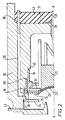
- an electron gun arrangement includes a generally circularly cylindrical ceramic body 20 which partly defines a vacuum envelope and encloses a volume within which is located an electron gun assembly consisting of a thermionic cathode 21, mesh grids 22 and 23, a focusing electrode 24 and an anode 25.
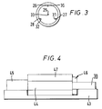
- the ceramic body 20 has four longitudinally extending apertures therethrough, the first three of which 26, 27 and 28 are located around the periphery of the body 20, as shown in Figure 3, and the fourth aperture 29 being located along the longitudinal axis X-X of the electron gun arrangement. Connections are made to parts of the electrode assembly via the apertures.
- Each of the apertures 26 to 29 includes a pin 30, 31, 32 and 33 respectively which is extensive of the aperture and via which external connection is made to the electrode assembly.
- the mesh electrodes 22 and 23 are mounted on annular metallic rings 33 and 34 which are supported by cylindrical metal segments 35 and 36 respectively.
- the electrode 24 is constituted by an annular ring which is also mounted on a generally cylindrical conductive member 37.
- the three cylindrical members 35, 36 and 37 are fixed to inner surfaces of the ceramic body 20.
- the interior of the body 20 is configured to define three circumferential ridges 38, 39 and 40 and the exterior surfaces of the cylindrical segments 35 to 37 are attached to the longitudinal surfaces between the circumferential ridges.
- the anode 25 is brazed to an end ring 41 at the left hand end of the ceramic body 20 as shown.
- the right hand end of the ceramic body 20 is extensive over a longer axial direction at its outer circumference than its inner portion. This increases the path length along the body 20 between the anode connection 25 and the pins 30 to 33 extensive from the apertures 26 to 29.
- a layer 42 of electrically insulating rubber material surrounds the pins 30 to 33 to provide electrical insulation.
- FIG. 4 schematically illustrates a travelling wave tube device in accordance with the invention.
- the outer surface of the ceramic body 20 is metallised and brazed to a base plate 43 to fix it into position.
- the electron gun arrangement is located at the right hand side as shown and is connected to a slow wave structure 44 which in turn is connected to a collector 45.
- the other two components making up the device are also mounted on the base plate 43, which has a curved upper surface to receive the outer surfaces of the various sections.
- a magnet 46 which in this case is formed by permanent magnetic material but which could be an electromagnet, is located at the left hand side of the electron gun arrangement as shown.
- the magnet surrounds the outer circumference of the ceramic body 20 and is arranged to produce a magnetic field in the region of the gun between the cathode 21 and the anode 25.
- the slow wave structure also includes a plurality of magnets 47 stacked along its length. As the gun arrangement is compact, having a relatively small diameter compared to previous arrangements, the addition of the magnet 46 does not appreciably add to the overall diameter occupied by the travelling wave tube.
Landscapes
- Microwave Tubes (AREA)
Applications Claiming Priority (2)
| Application Number | Priority Date | Filing Date | Title |
|---|---|---|---|
| GB9220226 | 1992-09-24 | ||
| GB929220226A GB9220226D0 (en) | 1992-09-24 | 1992-09-24 | Electron gun assemblies |
Publications (2)
| Publication Number | Publication Date |
|---|---|
| EP0589606A2 true EP0589606A2 (de) | 1994-03-30 |
| EP0589606A3 EP0589606A3 (de) | 1995-02-01 |
Family
ID=10722462
Family Applications (1)
| Application Number | Title | Priority Date | Filing Date |
|---|---|---|---|
| EP93307233A Withdrawn EP0589606A3 (de) | 1992-09-24 | 1993-09-14 | Elektronenstrahlerzeugungsvorrichtungen. |
Country Status (2)
| Country | Link |
|---|---|
| EP (1) | EP0589606A3 (de) |
| GB (1) | GB9220226D0 (de) |
Cited By (10)
| Publication number | Priority date | Publication date | Assignee | Title |
|---|---|---|---|---|
| WO1998054744A1 (en) * | 1996-04-20 | 1998-12-03 | Eev Limited | Electron gun with a diamond grid |
| WO2001004924A1 (en) * | 1999-07-09 | 2001-01-18 | Advanced Electron Beams, Inc. | Electron beam accelerator |
| US6407492B1 (en) | 1997-01-02 | 2002-06-18 | Advanced Electron Beams, Inc. | Electron beam accelerator |
| JP5835822B1 (ja) * | 2014-06-30 | 2015-12-24 | Necネットワーク・センサ株式会社 | 高周波回路システム |
| US10603035B2 (en) | 2017-05-02 | 2020-03-31 | Covidien Lp | Surgical loading unit including an articulating end effector |
| US11241228B2 (en) | 2019-04-05 | 2022-02-08 | Covidien Lp | Surgical instrument including an adapter assembly and an articulating surgical loading unit |
| US11324502B2 (en) | 2017-05-02 | 2022-05-10 | Covidien Lp | Surgical loading unit including an articulating end effector |
| US11504117B2 (en) | 2020-04-02 | 2022-11-22 | Covidien Lp | Hand-held surgical instruments |
| US11510669B2 (en) | 2020-09-29 | 2022-11-29 | Covidien Lp | Hand-held surgical instruments |
| US11737747B2 (en) | 2019-12-17 | 2023-08-29 | Covidien Lp | Hand-held surgical instruments |
Family Cites Families (5)
| Publication number | Priority date | Publication date | Assignee | Title |
|---|---|---|---|---|
| BE564301A (de) * | 1957-02-13 | 1900-01-01 | ||
| GB1161877A (en) * | 1965-11-03 | 1969-08-20 | Emi Ltd | Improvements relating to Electron Discharged Devices, especially Klystrons. |
| JPS56141139A (en) * | 1980-04-07 | 1981-11-04 | Toshiba Corp | Electrode support insulator |
| JPS5819838A (ja) * | 1981-07-29 | 1983-02-05 | Nec Corp | 電流制御形ヘリツクス進行波管 |
| FR2641899A1 (fr) * | 1989-01-17 | 1990-07-20 | Thomson Tubes Electroniques | Canon a electrons muni d'un dispositif actif produisant un champ magnetique au voisinage de la cathode |
-
1992
- 1992-09-24 GB GB929220226A patent/GB9220226D0/en active Pending
-
1993
- 1993-09-14 EP EP93307233A patent/EP0589606A3/de not_active Withdrawn
Cited By (15)
| Publication number | Priority date | Publication date | Assignee | Title |
|---|---|---|---|---|
| WO1998054744A1 (en) * | 1996-04-20 | 1998-12-03 | Eev Limited | Electron gun with a diamond grid |
| US6407492B1 (en) | 1997-01-02 | 2002-06-18 | Advanced Electron Beams, Inc. | Electron beam accelerator |
| WO2001004924A1 (en) * | 1999-07-09 | 2001-01-18 | Advanced Electron Beams, Inc. | Electron beam accelerator |
| JP5835822B1 (ja) * | 2014-06-30 | 2015-12-24 | Necネットワーク・センサ株式会社 | 高周波回路システム |
| WO2016002183A1 (ja) * | 2014-06-30 | 2016-01-07 | Necネットワーク・センサ株式会社 | 進行波管及び高周波回路システム |
| US10068738B2 (en) | 2014-06-30 | 2018-09-04 | Nec Network And Sensor Systems, Ltd. | Traveling wave tube and high-frequency circuit system |
| US10603035B2 (en) | 2017-05-02 | 2020-03-31 | Covidien Lp | Surgical loading unit including an articulating end effector |
| US11324502B2 (en) | 2017-05-02 | 2022-05-10 | Covidien Lp | Surgical loading unit including an articulating end effector |
| US11723660B2 (en) | 2017-05-02 | 2023-08-15 | Covidien Lp | Surgical loading unit including an articulating end effector |
| US11241228B2 (en) | 2019-04-05 | 2022-02-08 | Covidien Lp | Surgical instrument including an adapter assembly and an articulating surgical loading unit |
| US11925348B2 (en) | 2019-04-05 | 2024-03-12 | Covidien Lp | Surgical instrument including an adapter assembly and an articulating surgical loading unit |
| US11737747B2 (en) | 2019-12-17 | 2023-08-29 | Covidien Lp | Hand-held surgical instruments |
| US12268387B2 (en) | 2019-12-17 | 2025-04-08 | Covidien Lp | Hand-held surgical instruments |
| US11504117B2 (en) | 2020-04-02 | 2022-11-22 | Covidien Lp | Hand-held surgical instruments |
| US11510669B2 (en) | 2020-09-29 | 2022-11-29 | Covidien Lp | Hand-held surgical instruments |
Also Published As
| Publication number | Publication date |
|---|---|
| EP0589606A3 (de) | 1995-02-01 |
| GB9220226D0 (en) | 1992-11-04 |
Similar Documents
| Publication | Publication Date | Title |
|---|---|---|
| US6747412B2 (en) | Traveling wave tube and method of manufacture | |
| US6147447A (en) | Electronic gun for multibeam electron tube and multibeam electron tube with the electron gun | |
| RU2084042C1 (ru) | Клистрод | |
| EP0203805B1 (de) | Elektronenkanone | |
| US2942128A (en) | Electrodes for electron gun unit | |
| GB2182805A (en) | Vacuum interrupter | |
| US3979634A (en) | Travelling-wave tube with an improved electron gun | |
| GB2271020A (en) | Electron gun arrangements | |
| US3227913A (en) | Beam tube and circuitry therefor | |
| US3538368A (en) | Electron gun structure employing a unitary cylinder housing | |
| US3971965A (en) | Internally-focused traveling wave tube | |
| US3132275A (en) | Electron gun and cathode heater assembly therefor | |
| US3255377A (en) | Reverse magnetron with cathode support structure | |
| JPH0155539B2 (de) | ||
| US2943227A (en) | Electron gun support | |
| US5942847A (en) | Cathode ray tube | |
| CN114412739B (zh) | 一种大功率霍尔推力器磁路组件 | |
| US4680500A (en) | Integral grid/cathode for vacuum tubes | |
| US2707757A (en) | Electron discharge device | |
| CA2159253C (en) | Linear electron beam tube | |
| US3277328A (en) | Support means for cathode ray tube gun structure | |
| US3300678A (en) | Traveling wave tube with plural pole piece assemblies defining a vacuum sealed tube body and particular collector structure | |
| EP0144317B2 (de) | Gitterstruktur für gewisse, in mehreren betriebsweisen steuerbare elektronenstrahlerzeuger | |
| US5017827A (en) | Compactly built electron tube and fabrication method thereof | |
| US5990621A (en) | Electron beam tubes including ceramic material for realizing rf chokes |
Legal Events
| Date | Code | Title | Description |
|---|---|---|---|
| PUAI | Public reference made under article 153(3) epc to a published international application that has entered the european phase |
Free format text: ORIGINAL CODE: 0009012 |
|
| AK | Designated contracting states |
Kind code of ref document: A2 Designated state(s): DE FR GB SE |
|
| PUAL | Search report despatched |
Free format text: ORIGINAL CODE: 0009013 |
|
| AK | Designated contracting states |
Kind code of ref document: A3 Designated state(s): DE FR GB SE |
|
| STAA | Information on the status of an ep patent application or granted ep patent |
Free format text: STATUS: THE APPLICATION IS DEEMED TO BE WITHDRAWN |
|
| 18D | Application deemed to be withdrawn |
Effective date: 19950802 |