EP0589558B1 - Stereoscopic display method and display apparatus - Google Patents
Stereoscopic display method and display apparatus Download PDFInfo
- Publication number
- EP0589558B1 EP0589558B1 EP93306161A EP93306161A EP0589558B1 EP 0589558 B1 EP0589558 B1 EP 0589558B1 EP 93306161 A EP93306161 A EP 93306161A EP 93306161 A EP93306161 A EP 93306161A EP 0589558 B1 EP0589558 B1 EP 0589558B1
- Authority
- EP
- European Patent Office
- Prior art keywords
- hologram
- image
- individual
- dimensional
- different
- Prior art date
- Legal status (The legal status is an assumption and is not a legal conclusion. Google has not performed a legal analysis and makes no representation as to the accuracy of the status listed.)
- Expired - Lifetime
Links
- 238000000034 method Methods 0.000 title claims description 82
- 230000015572 biosynthetic process Effects 0.000 claims description 81
- 238000009826 distribution Methods 0.000 claims description 48
- 239000004973 liquid crystal related substance Substances 0.000 claims description 46
- 230000033458 reproduction Effects 0.000 claims description 43
- 239000002131 composite material Substances 0.000 claims description 33
- 230000003287 optical effect Effects 0.000 claims description 23
- 239000000470 constituent Substances 0.000 claims description 20
- 230000008569 process Effects 0.000 claims description 18
- 238000005286 illumination Methods 0.000 claims description 8
- 230000005484 gravity Effects 0.000 claims description 4
- 230000001678 irradiating effect Effects 0.000 claims description 4
- 230000009467 reduction Effects 0.000 claims description 2
- 238000010586 diagram Methods 0.000 description 35
- 230000008859 change Effects 0.000 description 6
- 230000003595 spectral effect Effects 0.000 description 6
- 239000000758 substrate Substances 0.000 description 6
- 239000011521 glass Substances 0.000 description 5
- 238000005070 sampling Methods 0.000 description 5
- 210000002858 crystal cell Anatomy 0.000 description 4
- 230000004907 flux Effects 0.000 description 3
- 239000004065 semiconductor Substances 0.000 description 3
- 230000005540 biological transmission Effects 0.000 description 2
- 238000006243 chemical reaction Methods 0.000 description 2
- 238000010276 construction Methods 0.000 description 2
- 238000006073 displacement reaction Methods 0.000 description 2
- 238000004519 manufacturing process Methods 0.000 description 2
- 230000002093 peripheral effect Effects 0.000 description 2
- 238000003786 synthesis reaction Methods 0.000 description 2
- 230000004308 accommodation Effects 0.000 description 1
- 230000001427 coherent effect Effects 0.000 description 1
- 230000003247 decreasing effect Effects 0.000 description 1
- 230000001934 delay Effects 0.000 description 1
- 238000001514 detection method Methods 0.000 description 1
- 230000000694 effects Effects 0.000 description 1
- 239000000835 fiber Substances 0.000 description 1
- 230000014509 gene expression Effects 0.000 description 1
- 229910052736 halogen Inorganic materials 0.000 description 1
- 150000002367 halogens Chemical class 0.000 description 1
- 239000011159 matrix material Substances 0.000 description 1
- 239000013307 optical fiber Substances 0.000 description 1
- 230000010287 polarization Effects 0.000 description 1
- 230000000644 propagated effect Effects 0.000 description 1
- 230000000717 retained effect Effects 0.000 description 1
- 238000000926 separation method Methods 0.000 description 1
- 230000003068 static effect Effects 0.000 description 1
- 230000002194 synthesizing effect Effects 0.000 description 1
- 230000000007 visual effect Effects 0.000 description 1
Images


Classifications
-
- G—PHYSICS
- G03—PHOTOGRAPHY; CINEMATOGRAPHY; ANALOGOUS TECHNIQUES USING WAVES OTHER THAN OPTICAL WAVES; ELECTROGRAPHY; HOLOGRAPHY
- G03H—HOLOGRAPHIC PROCESSES OR APPARATUS
- G03H1/00—Holographic processes or apparatus using light, infrared or ultraviolet waves for obtaining holograms or for obtaining an image from them; Details peculiar thereto
- G03H1/26—Processes or apparatus specially adapted to produce multiple sub- holograms or to obtain images from them, e.g. multicolour technique
- G03H1/268—Holographic stereogram
-
- G—PHYSICS
- G03—PHOTOGRAPHY; CINEMATOGRAPHY; ANALOGOUS TECHNIQUES USING WAVES OTHER THAN OPTICAL WAVES; ELECTROGRAPHY; HOLOGRAPHY
- G03H—HOLOGRAPHIC PROCESSES OR APPARATUS
- G03H1/00—Holographic processes or apparatus using light, infrared or ultraviolet waves for obtaining holograms or for obtaining an image from them; Details peculiar thereto
- G03H1/04—Processes or apparatus for producing holograms
- G03H1/08—Synthesising holograms, i.e. holograms synthesized from objects or objects from holograms
-
- G—PHYSICS
- G03—PHOTOGRAPHY; CINEMATOGRAPHY; ANALOGOUS TECHNIQUES USING WAVES OTHER THAN OPTICAL WAVES; ELECTROGRAPHY; HOLOGRAPHY
- G03H—HOLOGRAPHIC PROCESSES OR APPARATUS
- G03H1/00—Holographic processes or apparatus using light, infrared or ultraviolet waves for obtaining holograms or for obtaining an image from them; Details peculiar thereto
- G03H1/26—Processes or apparatus specially adapted to produce multiple sub- holograms or to obtain images from them, e.g. multicolour technique
- G03H1/28—Processes or apparatus specially adapted to produce multiple sub- holograms or to obtain images from them, e.g. multicolour technique superimposed holograms only
-
- G—PHYSICS
- G03—PHOTOGRAPHY; CINEMATOGRAPHY; ANALOGOUS TECHNIQUES USING WAVES OTHER THAN OPTICAL WAVES; ELECTROGRAPHY; HOLOGRAPHY
- G03H—HOLOGRAPHIC PROCESSES OR APPARATUS
- G03H1/00—Holographic processes or apparatus using light, infrared or ultraviolet waves for obtaining holograms or for obtaining an image from them; Details peculiar thereto
- G03H1/04—Processes or apparatus for producing holograms
- G03H1/0402—Recording geometries or arrangements
- G03H1/0406—Image plane or focused image holograms, i.e. an image of the object or holobject is formed on, in or across the recording plane
-
- G—PHYSICS
- G03—PHOTOGRAPHY; CINEMATOGRAPHY; ANALOGOUS TECHNIQUES USING WAVES OTHER THAN OPTICAL WAVES; ELECTROGRAPHY; HOLOGRAPHY
- G03H—HOLOGRAPHIC PROCESSES OR APPARATUS
- G03H1/00—Holographic processes or apparatus using light, infrared or ultraviolet waves for obtaining holograms or for obtaining an image from them; Details peculiar thereto
- G03H1/04—Processes or apparatus for producing holograms
- G03H1/0402—Recording geometries or arrangements
- G03H1/0408—Total internal reflection [TIR] holograms, e.g. edge lit or substrate mode holograms
-
- G—PHYSICS
- G03—PHOTOGRAPHY; CINEMATOGRAPHY; ANALOGOUS TECHNIQUES USING WAVES OTHER THAN OPTICAL WAVES; ELECTROGRAPHY; HOLOGRAPHY
- G03H—HOLOGRAPHIC PROCESSES OR APPARATUS
- G03H1/00—Holographic processes or apparatus using light, infrared or ultraviolet waves for obtaining holograms or for obtaining an image from them; Details peculiar thereto
- G03H1/04—Processes or apparatus for producing holograms
- G03H1/08—Synthesising holograms, i.e. holograms synthesized from objects or objects from holograms
- G03H1/0808—Methods of numerical synthesis, e.g. coherent ray tracing [CRT], diffraction specific
-
- G—PHYSICS
- G03—PHOTOGRAPHY; CINEMATOGRAPHY; ANALOGOUS TECHNIQUES USING WAVES OTHER THAN OPTICAL WAVES; ELECTROGRAPHY; HOLOGRAPHY
- G03H—HOLOGRAPHIC PROCESSES OR APPARATUS
- G03H1/00—Holographic processes or apparatus using light, infrared or ultraviolet waves for obtaining holograms or for obtaining an image from them; Details peculiar thereto
- G03H1/22—Processes or apparatus for obtaining an optical image from holograms
- G03H1/2294—Addressing the hologram to an active spatial light modulator
-
- G—PHYSICS
- G03—PHOTOGRAPHY; CINEMATOGRAPHY; ANALOGOUS TECHNIQUES USING WAVES OTHER THAN OPTICAL WAVES; ELECTROGRAPHY; HOLOGRAPHY
- G03H—HOLOGRAPHIC PROCESSES OR APPARATUS
- G03H2210/00—Object characteristics
- G03H2210/30—3D object
- G03H2210/33—3D/2D, i.e. the object is formed of stratified 2D planes, e.g. tomographic data
-
- G—PHYSICS
- G03—PHOTOGRAPHY; CINEMATOGRAPHY; ANALOGOUS TECHNIQUES USING WAVES OTHER THAN OPTICAL WAVES; ELECTROGRAPHY; HOLOGRAPHY
- G03H—HOLOGRAPHIC PROCESSES OR APPARATUS
- G03H2210/00—Object characteristics
- G03H2210/30—3D object
- G03H2210/36—Occluded features resolved due to parallax selectivity
-
- G—PHYSICS
- G03—PHOTOGRAPHY; CINEMATOGRAPHY; ANALOGOUS TECHNIQUES USING WAVES OTHER THAN OPTICAL WAVES; ELECTROGRAPHY; HOLOGRAPHY
- G03H—HOLOGRAPHIC PROCESSES OR APPARATUS
- G03H2210/00—Object characteristics
- G03H2210/40—Synthetic representation, i.e. digital or optical object decomposition
- G03H2210/45—Representation of the decomposed object
- G03H2210/452—Representation of the decomposed object into points
-
- G—PHYSICS
- G03—PHOTOGRAPHY; CINEMATOGRAPHY; ANALOGOUS TECHNIQUES USING WAVES OTHER THAN OPTICAL WAVES; ELECTROGRAPHY; HOLOGRAPHY
- G03H—HOLOGRAPHIC PROCESSES OR APPARATUS
- G03H2225/00—Active addressable light modulator
- G03H2225/20—Nature, e.g. e-beam addressed
- G03H2225/25—Optically addressed SLM [OA-SLM]
-
- G—PHYSICS
- G03—PHOTOGRAPHY; CINEMATOGRAPHY; ANALOGOUS TECHNIQUES USING WAVES OTHER THAN OPTICAL WAVES; ELECTROGRAPHY; HOLOGRAPHY
- G03H—HOLOGRAPHIC PROCESSES OR APPARATUS
- G03H2225/00—Active addressable light modulator
- G03H2225/30—Modulation
- G03H2225/32—Phase only
-
- Y—GENERAL TAGGING OF NEW TECHNOLOGICAL DEVELOPMENTS; GENERAL TAGGING OF CROSS-SECTIONAL TECHNOLOGIES SPANNING OVER SEVERAL SECTIONS OF THE IPC; TECHNICAL SUBJECTS COVERED BY FORMER USPC CROSS-REFERENCE ART COLLECTIONS [XRACs] AND DIGESTS
- Y10—TECHNICAL SUBJECTS COVERED BY FORMER USPC
- Y10S—TECHNICAL SUBJECTS COVERED BY FORMER USPC CROSS-REFERENCE ART COLLECTIONS [XRACs] AND DIGESTS
- Y10S359/00—Optical: systems and elements
- Y10S359/90—Methods
Definitions
- the present invention relates to the production of holograms for use in producing stereoscopic displays.
- a stereoscopic display is a display for enabling depth or thickness of a three-dimensional object to be easily visually appreciated.
- Stereoscopic display is useful for the display of a structural object designed by CAD, or the like, and for the display of a medical image or the like.
- a three-dimensional image is also more impressive than a two-dimensional display, and this makes stereoscopic displays desirable for amusement in an amusement park, a cinema, or the like.
- a hologram can be used.
- holographic projection an observer can see a three-dimensional image without using special glasses.
- an object image is recorded by using light interference.
- Colour holograms giving an impression of depth have already been produced for static images.
- computer graphics CG
- a virtual object having a three-dimensional structure is formed by CAD or the like.
- Computer generated composite holograms can be used, to reconstruct an image of a three-dimensional object, as described in an article by Toyohiko Yatagai in Applied Optics, Volume 15, No. 11, pages 2722 to 2728 (Nov. 1976).
- a sequence of perspective projections of the three-dimensional object to be displayed is calculated and corresponding holograms are generated by a computer and arranged in sequence to synthesize a composite hologram.
- a conventional hologram is recorded onto a film-like medium and it takes time to develop the image. Such delay may be inconvenient in a stereoscopic display system. Further, the contents of such a display cannot be rewritten.
- a method of producing a composite hologram for use in displaying a stereoscopic image of a three-dimensional subject located in an object space extending away from a hologram formation surface comprising:
- an apparatus for producing a composite hologram for use in displaying a stereoscopic image of a three-dimensional subject located in an object space extending away from a hologram formation surface which apparatus comprises:
- An embodiment of the present invention can be used to display a holographic image, for example a moving image, which can be viewed over long periods with little fatigue, the image being rewritten in a real-time manner.
- Three-dimensional coordinate data for use in an embodiment of the invention can for example be formed from two-dimensional image input data obtained by photographing an object with a CCD camera or the like.
- Embodiments of the invention can provide for hologram formation by multiple exposure of a recording medium to a plurality of two-dimensional images.
- three-dimensional information to be expressed is divided in the depth direction, a plurality of three-dimensional zones, or regions, are set, zone data indicative of the three-dimensional information of the object to be displayed is formed for each zone and a plurality of depth image data sets comprising the two-dimensional image data is formed for each zone.
- the zones in the depth direction can be set such that one zone is set separately for each object to be expressed or such that one object is divided into a plurality of portions, each portion being assigned to a different zone.
- a projection plane which is parallel with the hologram forming surface is set in each region, and projection data of an object or objects as seen from the hologram formation surface, projected onto the two-dimensional plane, is produced as two-dimensional depth image data.
- phase is calculated on the basis of two-dimensional pixels of which the depth image is constructed, so as to form a phase distribution constituting a segment hologram at the hologram formation surface.
- the phase distributions obtained for each of the plurality of depth images are added to each segment hologram at the same position, thereby obtaining a phase distribution at the hologram forming surface of a synthesized depth image.
- the spatial phase distribution of a hologram is calculated from a plurality of two-dimensional depth images and the phase distribution obtained is expressed, i.e. reproduced in physical form, by means for spatially modulating the amplitude or phase of reproduction light.
- Rewritable stereoscopic display can be performed by optical wavefront conversion of a reproduction light beam.
- a plurality of depth images can be recorded in a multiplex manner on a recording medium by light interference exposure, to form each of the segment holograms.
- the segment holograms obtained are arranged and recorded on a hologram dry plate to form the composite hologram.
- Conventional holographic display techniques can then be applied to reproduce the holographic image from the recording medium.
- each segment hologram is based on a plurality of two-dimensional depth images, relating respectively to different depths of the object space, serves to reduce the difference between the distances at which an observer perceives an image to be located on the basis of eye parallax, on the one hand, and on the basis of eye focus (i.e. accommodation) on the other hand. Fatigue from viewing the holographic display can thus be decreased and, at the same time, a more natural three-dimensional representation is obtainable.
- an embodiment of the present invention can enable a more natural stereoscopic display to be realized, as compared with conventional holographic stereograms.
- a CAD system can be used to electronically form holograms from virtual objects, so that stereoscopic images can be rewritten and displayed in a short time.
- colour stereoscopic displays can also be readily achieved.
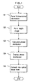
- Fig. 1 illustrates a stereoscopic display method in which:
- step S1 three-dimensional coordinate data constituting image information representing a subject consisting of an object or objects to be displayed, is formed from three-dimensional image data by a CAD system, or from two-dimensional data obtained by photographing the objects with a CCD camera or the like.
- step S2 a plurality of depth images are formed by deriving 2-dimensional information from the three-dimensional image information.
- the space containing the objects to be displayed, as seen from a hologram formation surface is divided up in the depth direction into a plurality of different spatial zones.
- Depth image data, as projected onto a projection plane set in each zone, each such plane being parallel to the hologram forming surface, is then formed.
- step S3 a phase distribution at the hologram formation surface is calculated from the plurality of depth images.
- step S4 the calculated phase distribution is reproduced physically so as to be expressed at the hologram formation surface. Irradiation of that surface with reproduction light then causes a three-dimensional image to be displayed as a result of optical wavefront conversion according to the expressed phase distribution.
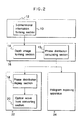
- FIG. 2 shows the construction of an apparatus for performing the stereoscopic display method illustrated in Fig. 1.
- a three-dimensional image information forming section 10 is realized by, for example, a CAD system 12.
- Three-dimensional image data representing objects to be displayed is formed by the three-dimensional image information forming section 10 and is given to a depth image forming section 14, which derives therefrom a plurality of two-dimensional images located at different positions in the depth direction.
- the images formed by the depth image forming section 14 are given to a phase distribution calculating section 15, which calculates a corresponding phase distribution at the hologram formation surface.
- the depth image forming section 14 and the phase distribution calculating section 15 are realized by a computer 16.
- the results of the calculation performed by the phase distribution calculating section 15 are given to a phase distribution display section 18.
- a three-dimensional image is displayed by an optical wavefront converting section 20.
- the phase distribution display section 18 and the optical wavefront converting section 20 form a hologram display apparatus 22.
- a plurality of two-dimensional image data sets, formed by the depth image forming section 14 for respective different positions in the depth direction, are given to a hologram exposing apparatus 24 and are used as a basis for recording holograms on a hologram dry plate, serving as a recording medium, by multiple exposure.
- a hologram can thus be formed as a fixed record.
- An expressing format of three-dimensional image data in computer graphics can be used in the formation of the three-dimensional image information of an object to be stereoscopically displayed.
- an object 26 having three-dimensional structure may be separated into a set of planes 28 as shown in Fig. 3. Lists of contours or vertices of the planes are linked, thereby forming three-dimensional image data.
- the object 26 may be expressed by a set of basic shapes 30-1, 30-2 and 30-3.
- the object 26 is expressed by using logic arithmetic operating expressions 32 defining the combination of basic shapes 30-1 to 30-3.
- Such expressing formats of the three-dimensional image data shown in Figs. 3 and 4 are widely used in the field of computer graphics.
- the three-dimensional image data can be produced from CAD data by using a CAD system as shown in Fig. 2.
- Fig. 5 shows in more detail the Fig. 1 step of forming depth images.
- step S1 of Fig. 5 the three-dimensional image data is divided into sets corresponding to a plurality of different spatial zones (regions) in the depth direction.
- step S2 of Fig. 5 three-dimensional image data is formed for each zone (region).
- step S3 of Fig. 5 two-dimensional depth image data is formed for each zone.
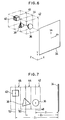
- Fig. 6 shows the depthwise division of an object space in which three objects 36, 38 and 40 are arranged, spaced apart from one another in the depth direction, each of these objects having a three-dimensional structure to be displayed.
- a hologram formation surface 34 is set at an arbitrary position relative to the objects 36, 38 and 40. Spatial zones 42, 44 and 46 are set, spanning respective different ranges of distance from the surface 34 and respectively containing the objects 36, 38 and 40. These zones are arranged in sequence in the depth direction that is perpendicular to the hologram formation surface 34.
- a lateral direction of the hologram formation surface 34 is taken as an X axis, a vertical direction as a Y axis, and the depth direction as a Z axis in the object space.
- a two-dimensional coordinate system of independent two-dimensional coordinates X h and Y h is set for the hologram formation surface 34.
- Fig. 7 shows a side elevational view of Fig. 6.
- the object 36 belongs to the zone 42 lying nearest to the hologram formation surface 34.
- the object 38 belongs to the adjacent zone 44.
- the object 40 belongs to the zone 46 lying furthest from the hologram formation surface 34.
- Figures 6 and 7 show a case in which it is possible to allocate separate objects into respective separate, non-overlapping, depth zones. In many cases, however, objects will overlap in the depth direction.
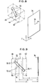
- Fig. 8 shows zonal divisions for a single object 70 which is extensive in the depth direction.
- the zones 42, 44 and 46 are chosen so as to subdivide the object 70 into three portions in the depth direction.
- Fig. 9 shows a side view of the zonal divisions of Fig. 8.
- each three-dimensional image data set is produced as a zonal data set which expresses the content of one zone. That is, in Figs. 6 and 7, after completion of the zonal division, independent three-dimensional image data is obtained for each object 36, 38 and 40. In Figs. 8 and 9, after completion of the division, three-dimensional image data sets indicative respectively of three object parts, constituted by the divided cylindrical portions 70-1, 70-2 and 70-3, are obtained.
- Fig. 10 shows the general depth division of three-dimensional image data.
- objects 90, 92, 94, 96 and 98 are arrayed in the depth direction in relation to the hologram formation surface 34.
- Individual depth zones 80, 82 and 84 are set respectively for the objects 90, 92 and 94.
- a single background zone 86, furthest from the hologram formation surface 34, extends to infinity so as to contain the objects 96 and 98 spaced at distances greater than or equal to a predetermined distance from the hologram formation surface 34.
- two-dimensional projection data is formed for each zone.
- projection planes 48, 50 and 52 are shown set for use respectively in forming the two-dimensional projection data sets for the three zones. These planes lie parallel to the hologram formation surface 34 and pass through the respective geometrical centres of gravity of the objects 36, 38 and 40.
- a plurality of two-dimensional image data sets are formed, representing perspective images of the objects 36, 38 and 40, as viewed from a plurality of different viewpoints on the hologram formation surface 34, projected onto their corresponding projection planes 48, 50 and 52, the distances from the planes 48, 50 and 52 to the hologram forming surface 34 having been previously obtained as Z 1 , Z 2 and Z 3 respectively.
- projection planes 72, 74 and 76 are set in a similar manner, these planes lying parallel to the hologram formation surface 34 and passing through the geometrical centres of gravity of the respective cylindrical object portions 70-1, 70-2, and 70-3 in the zones 42, 44, and 46.
- the distances Z 1 , Z 2 and Z 3 in the depth direction are precalculated.
- projection planes 100, 102 and 104 are set in a similar manner with respect to the zones 80, 82 and 84, at the positions of the relevant centres of gravity which are calculated as being at distances Z 1 , Z 2 and Z 3 respectively.
- a projection plane 106 is set for the background zone 86, at a distance Z 4 in the depth direction from the hologram formation surface 34.
- the two-dimensional projection data of all of the objects in the background zone 86 (in this case the objects 96 and 98) is formed in relation to their images as projected onto the plane 106.
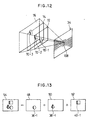
- Fig. 11 shows the principles of forming the two-dimensional depth images for the Fig. 6 arrangement.
- the hologram formation surface 34 is divided up into small areal segments in a matrix-like manner, thereby forming segment hologram areas 108 as minimum units of a composite hologram to be realized.
- the size of each of the segment hologram areas 108 is set to about 1 mm or less in each of the vertical and horizontal directions. For the sake of simplicity, the segment hologram areas are shown larger than they would be in practice.
- Two-dimensional pixel information is formed as two-dimensional image data, related to the planes 48, 50 and 52, for each of the segment hologram areas 108 used in turn as a point from which to view the objects 36, 38 and 40 in the respective zones.
- the three-dimensional pixel data representing the object 36 is converted into plane pixel data representing that object as seen, projected onto the plane 48, from the viewpoint of the central segment hologram area 108 of the hologram formation surface 34.
- Fig. 13 shows two-dimensional image data 36-1, 38-1 and 40-1 related respectively to the planes 48, 50 and 52 and obtained by setting as a viewpoint the central segment hologram area 108 in Fig. 11. By superimposing those data, a synthesized complete two-dimensional depth image data set 54 can be obtained.
- Fig. 14 shows the two-dimensional image data sets 70-1, 70-2 and 70-3 corresponding respectively to the planes 72, 74 and 76 of Fig. 12 when the viewpoint is set to the central segment hologram 108.
- a synthesized complete two-dimensional depth image 78 in this case two-dimensional image data 70-10 of a continuous cylindrical body, can be obtained.
- the method whereby two-dimensional images of an object viewed from a plurality of different directions are formed on the basis of the three-dimensional data as mentioned above can be realized by using the three-dimensional display technique in conventional computer graphics.
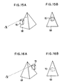
- processing of hidden lines or hidden areas is also included so that the side surface which is seen is changed in accordance with the direction of observation.
- a 'hidden area' process is executed whereby the part of the plane of the object 68 obscured by the object 70 is not displayed, the resulting image being as shown in Fig. 15B.
- the 'hidden area' process results in the object 70 not being displayed at all since it is fully obscured by the object 68, as indicated schematically in Fig. 16B.
- the change in direction of observation of an object when viewed from one of the segment hologram areas 108, as compared with the direction when viewed from an adjacent segment hologram area 108, can be in a range from about 0.3 degree to 1 degree.
- successive viewpoints may be set by changing the direction of observation in each case by a predetermined angle within a range from about 0.3 to 1 degree in both of the horizontal and vertical directions, using the centre of the hologram formation surface 34 as a starting point, and two-dimensional image data for each zone can be calculated for each viewpoint position determined in this way.
- a single laser beam is divided into two beams, one of which serves as a reference light beam and the other of which is used to irradiate an object. Some of the light of the latter beam is scattered back by the object to provide an object light flux.
- a spatial light modulation device such as a liquid crystal device or the like, which can change the amplitude and phase of light incident thereon, can be used.
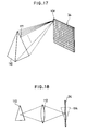
- An image of the object can be reproduced for viewing by irradiating the hologram with a wavefront equivalent to that of the reference light beam.
- the exposure intensity I H of equation (1) only the third term of the right-hand side contributes to the reproduction of the object light.
- the first term on the right-hand side of equation (2) denotes that the wavefront from the object was reproduced.
- the second term on the right-hand side indicates a conjugate wave of the object light. From the above description, it will be understood that it is sufficient to calculate only the third term of the right-hand side of the equation (1) in the calculation of the phase distribution of a hologram.
- the image of the object 110 is formed as a real image 114 at the position of the hologram formation surface 34 by an image forming lens 112. Therefore, as shown in Fig. 19, for example, light from a sampling point 115 of the real image 114 reaches only the portion 117 of the hologram formation surface 34, which portion is determined by a virtual opening 116. The region over which equations (3) and (4) need to be calculated is thus limited.
- each two-dimensional pixel of each of the two-dimensional depth image data sets obtained respectively from the objects 36, 38 and 40 in the three defined zones is taken as a sampling point and the equations (3) and (4) are calculated.
- Exposure intensities (I Hi ) 1 , (I Hi ) 2 and (I Hi ) 3 for the hologram are obtained for the respective zones.
- the phase distribution of one segment hologram 108 is then calculated as the sum of these exposure intensities obtained for the different zones. This is expressed by the following general equation with respect to zone numbers 1 to n.
- I HI (I Hi ) 1 + (I Hi ) 2 + ... + (I Hi ) n
- the size of a three-dimensional image displayed may be adjusted by the following method.
- Fig. 20 shows the hologram formation surface 34 and a two-dimensional depth image display surface (projection plane) 118 which are separated by a predetermined distance.
- An image 120 is shown projected onto the image display surface 118.
- the image 120 is shown as an upward arrow.
- a centre line 122 is shown extending in the Z-axis direction and passing through an origin point O on the image display surface 118 and a point P 0 on the hologram formation surface 34.
- the point P 0 corresponds to one segment hologram.
- a point P i corresponding to another segment hologram is shown above the point P 0 .
- the phase distribution at the point P 0 is obtained from all of the sampling points of the image 120 on the basis of the equations (3) and (4).
- the phase distribution at the point P i can be obtained from all of the sampling points of the image 120.
- the image 120 appears different when seen from P 0 as compared with P i , the difference being due only to parallax.
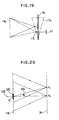
- the point P i is displayed about the origin O, relative to P 0 , by only an angle ⁇ i . If the image 120 is to be enlarged (or reduced), it is enlarged (or reduced) on the depth image display surface 118 around the origin O as a centre, and the phases at the points P 0 and P i are calculated on the basis of the result of the enlargement (or reduction).
- Fig. 21 shows a situation in which the image 120 of Fig. 20 is enlarged by a factor of two to obtain an image 120-1.
- the angle between the lines from the origin O to the points P 0 and P i respectively is ⁇ i , being unchanged.
- No contradiction occurs in the continuity of the parallax between the image seen from the point P 0 and the image seen from the point P i .
- the origin O of the image 120 is set to a sharp edge portion on the object such that it can be always seen at the same position even when the viewpoint position is changed on the hologram formation surface 34.
- Adjustment of the distance, from the hologram formation surface, at which a three-dimensional image is to be displayed can be achieved by the following method.
- Fig. 22 illustrates a change in the distance of a depth image display surface (projection plane), used to display an image 120-1, from the hologram formation surface 34.
- the image 120-1 on the depth image display surface 118-1 located at a distance L in the depth direction from the hologram formation surface 34, is processed for the different points P 0 and P i on the hologram formation surface 34.
- the angular displacement of the point P i from the point P 0 is just an angle ⁇ i .
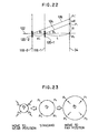
- Fig. 23 shows changes of four calculation points P 1 to P 4 distributed around the central phase distribution calculation point (segment hologram) P 0 .
- a case in which the image display surface is moved away from the hologram formation surface 34 is shown at the right-hand side of Figure 23, while the left-hand side shows a case in which the image display surface is moved nearer.
- the peripheral calculation points P 1 to P 4 approach one another more closely.
- the peripheral calculation points P 1 to P 4 are displaced radially outwardly and the distances between the calculation points increase.
- a two-dimensional depth image as seen from a position between the adjacent calculation points can be obtained by image interpolation.
- the phase distribution relating to the interpolation calculation point is calculated from the interpolation image, thereby maintaining the continuity of the reconstructed three-dimensional image in the case where the display surface was moved further away from the hologram formation surface.
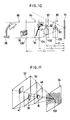
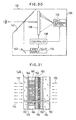
- Fig. 24 shows a hologram display apparatus for expressing the calculated phase distribution in physical form, as a composite hologram, and for displaying a three-dimensional image by irradiation of the composite hologram with a reproduction light beam.
- a spatial light modulation device 130 for electrically forming the composite hologram is provided at the front of an apparatus main body 128.
- a hood 132 is also provided to shield the zeroth order light transmitted through the device 130.
- Fig. 25 shows internal structure of the Fig. 24 apparatus.
- a laser light source 134 which functions as a point light source, a collimating mirror 136 and a controller 138 are disposed in the main body of the apparatus.
- the controller 138 gives the calculated phase distribution to the spatial light modulation device 130.
- a spherical wave originating as a point light source from the laser light source 134 is converted into a parallel reproduction light beam (i.e. collimated) by reflection at the collimating mirror 136 and is directed onto the spatial light modulation device 130, thereby causing a three-dimensional image 135 to be reconstructed.
- the part of the collimated light beam which passes directly through the spatial light modulation device 130 as a zeroth order component is blocked by the hood 132.
- the laser light source 134 is a small semiconductor laser with a spectral bandwidth of a few nanometres or less, which is capable of reconstructing a clear three-dimensional image. Any wavelength in the visible range can be used. It is, however, necessary to consider the wavelength of the light source, used for reconstruction, when calculating the hologram phase distribution. For example, it is possible to use a semiconductor laser which emits a red light beam whose wavelength is of the order of 600 nm, or one which emits a green light beam whose wavelength is of the order of 500 nm, or one which emits a blue light beam whose wavelength is of the order of 400 nm.
- the hologram is relatively insensitive to the colour distribution over the spectral bandwidth of the reproduction light. Therefore, a clear reproduction image can be obtained even when the spectral bandwidth of the source is relatively broad.
- a spherical wave is directly emitted from the laser light source 134 in Fig. 25, it is also possible to construct the apparatus in such a manner that a laser beam is passed through an objective lens and a pin hole, or such that a laser beam is transmitted through an optical fibre to provide light which disperses from an output end of the fibre.
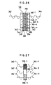
- Fig. 26 shows a spatial light modulation device 130, for use in an embodiment of the present invention, in which a liquid crystal display of the transmitting type is used.
- An input surface is provided by one side of a glass substrate 340, on the other side of which a uniform transparent electrode 344 is disposed.
- Branched transparent electrodes 346-1 to 346-n form display segments and are arranged on an inner face of a glass substrate 342 at an output side of the device.
- Liquid crystal orientation films 352 and 354 are provided inwardly of the transparent electrodes 344 and 346-1 to 346-n but separated therefrom respectively by insulating layers 348 and 350.
- a layer of liquid crystal 360 is disposed between the orientation films 352 and 354, so that the device constitutes a liquid crystal display panel.
- a voltage corresponding to the appropriate calculated phase information is applied to each liquid crystal cell in a manner determined by signals applied to the electrodes 346-1 to 346-n.
- the refractive index of the liquid crystal cell for the transmitting direction of a reproduction light beam 362 is thus locally modulated in accordance with the control voltages applied.
- Fig. 27 shows details of the phase modulation with respect to three of the pixels of the liquid crystal display as an example.
- Reproduction light beams 362-1 to 362-3 of the same phase enter from the left side into pixels 366-1 to 366-3.
- These pixels are driven in accordance with respective different phase states (so as to have different refractive indices) so that relative phase deviations exist between the outgoing light beams 364-1 to 364-3 as a result of their different optical path-lengths in the respective liquid crystal pixels 366-1 to 366-3.
- any phase in a range from 0 to 2 ⁇ can be expressed, which range corresponds to an optical distance of a full wavelength.
- the desired phase distribution can be expressed approximately within a practical range.
- the thickness d of the liquid crystal layer is selected so as to satisfy conditions such that the product An x d, of the thickness d and the maximum refractive index change ⁇ n which can be induced by the applied voltage, is equal to one wavelength ⁇ of the reproduction light.
- Fig. 28 shows another stereoscopic display apparatus, for use in an embodiment of the invention, in which a reflecting-type spatial light modulation device 130 is used.
- the device 130 is provided in the main body 128 of the apparatus and electronically expresses (i.e. forms a physical reproduction of) a hologram having the phase distribution calculated by the controller 138.
- a reproduction light beam from the laser light source 134 is reflected by a mirror 140 and is further reflected by a half mirror 142 so as to enter the reflecting type spatial light modulation device 130.
- Modulated light from the modulation device 130 passes through the half mirror 142, thereby displaying a three-dimensional image.
- the reproduction light first enters a reflection-type liquid crystal display 144 at one side of the device, is reflected by a reflecting surface 146 at the opposite side, traverses the display 144 once more, and is then emitted from the device. Since reproduction light passes through the liquid crystal display twice in such a reflection-type modulation device (as compared with only once in a transmission-type liquid crystal modulation device) the thickness of the liquid crystal layer needed to obtain a given phase change can be reduced by one half. It should be noted that in this embodiment a liquid crystal of the homogeneous orientation type is used so that its polarization is preserved.
- Fig. 30 shows another embodiment of a stereoscopic display apparatus.
- the information of the calculated phase distribution is optically written and reproduced.
- a spatial light modulation device 148 in which phase distribution information can be written optically by a laser beam from a light scanning section 145, is provided in the main body 128 of the apparatus.
- the controller 138 controls the modulation device 148 so that it provides the same conditions as in the reflection-type device 130 shown in Fig. 29.
- the laser beam from the laser light source 134 is reflected by the mirror 140 and the half mirror 142 and is incident on the left side of the spatial light modulation device 148 as a reproduction light beam.
- the image is then displayed via projection through the half mirror 142 to the observer.
- Fig. 31 shows internal structure of the optically writable spatial light modulation device 148 of Fig. 30.
- a transparent electrode 154, a photoconductive layer 156 and a light shielding layer 158 are arranged on one side of a glass substrate 150, the other side of which receives a writing light beam 170.
- a dielectric mirror 160 is provided inwardly of the light shielding layer 158.
- a glass substrate 152 is provided, on the side of the device which is opposite to that of the substrate 150, for receiving and re-emitting a reproduction light beam 172.
- a transparent electrode 155 is provided on the substrate 150.
- a liquid crystal layer 165 is arranged between insulating films 164 and 162 provided respectively on the transparent electrode 155 and the dielectric mirror 160.
- the spatial light modulation device 148 of Fig. 31 when the writing light beam 170 is first incident on the photoconductive layer 156, the resistance value of that layer drops where the light intensity is large. Since the resistance value of the photoconductive layer 156 changes, while the driving voltage is kept constant, the voltage which is applied across the corresponding part of the liquid crystal panel 165 through the dielectric mirror 160 changes locally by an amount corresponding to the resistance value change. When the voltage which is applied across part of the liquid crystal changes, as mentioned above, the refractive index changes locally. When the incident reproduction light beam 172 is reflected by the dielectric mirror 160 and is returned, the reproduction light becomes a modulation light beam 174 carrying phase modulation information.
- Fig. 32 shows another stereoscopic display apparatus for use in an embodiment of the invention.
- a reproduction light beam 180 enters the spatial light modulation device 130, which uses a transmission-type liquid crystal display or the like to express the calculated phase distribution, and is modulated thereby.
- the modulated light beam from the spatial light modulation device 130 is enlarged by a projection optical system 176 and is projected onto a hologram screen 178, thereby enabling a three-dimensional image to be observed over the visual field 182 corresponding to an angular visibility range ⁇ .
- Fig. 33 shows another embodiment of a stereoscopic display apparatus.
- a hood for preventing the zeroth order light component being displayed can be dispensed with.
- a refracting body for suppressing the emission of the zeroth order light is integrated with the spatial light modulation device 184 in the apparatus main body 128.
- a spherical wave from the laser light source 134 is reflected by the collimating mirror 136 and directed onto the spatial light modulation device 184, integrated with the refracting body, at an angle of incidence equal to or larger than the critical angle for the refracting body.
- the zeroth order light is therefore totally internally reflected, thereby preventing zeroth order light from being emitted.
- a hood to block out the zeroth order light is therefore not required.
- step S1 of Fig. 1 the formation of the depth image in step S2, and the calculation of the phase distribution in step S3, are executed for each spectral component, for example, for R, G and B components.
- Fig. 35 shows an embodiment of a colour stereoscopic display apparatus for producing a two-colour display, the apparatus comprising two of the stereoscopic display apparatuses described above.
- a spatial light modulation device 200 is driven in accordance with the phase distribution calculated with respect to, for example, the R component by a controller 226.
- a spatial light modulation device 202 is driven in accordance with the phase distribution calculated with respect to, for example, the G component.
- Respective reproduction light beams from laser light sources 206 and 208 irradiate the spatial light modulation devices 200 and 202 through shutters 212 and 214 and collimating lenses 216 and 218 respectively, thereby displaying a three-dimensional R component image 228 and a three-dimensional G component image 230.
- the G component image 230 is reflected by a half mirror 220 and is seen by the eyes 224 of the observer.
- the R component image 228 passes through the half mirror 220 and enters the eyes 224. Consequently, the observer can see a synthetic colour three-dimensional image in which the G component image 230 is superimposed on the R component image 228.
- Fig. 36 shows another colour stereoscopic display apparatus for use in an embodiment of the invention.
- the phase distribution is calculated for each of the R, G and B components to enable a synthesized colour image to be displayed.
- Three stereoscopic display apparatuses are used.
- a laser light source 210, a shutter 215 and a collimating lens 219 are provided to act as a display system for the B component.
- An additional spatial light modulation device 204 driven in accordance with the phase distribution calculated with respect to the B component, is also provided.
- a half mirror 222 is added for combining the B component image from the spatial light modulation device 204 with the R and G component images.
- a synthesized three-dimensional colour image, formed from the R, G and B components shown by arrows, can thus be observed by the eyes 224 of the observer.
- Fig. 37 shows a timing chart of driving signals E R , E G and E B for time-divisionally displaying the RGB components by opening or closing the shutters 212, 214, and 215, this being controlled by the controller 226 illustrated in Fig. 36.
- the driving signals E R , E G and E B are generated so as to be repeated at intervals T of 1/30 second and so have relative timing delays of T/3.
- the timing deviation between the two signals E R and E G can be set to T/2.
- Fig. 38 shows a timing chart of another driving method suitable for use with the embodiments of Figs. 35 and 36.
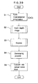
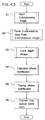
- Fig. 39 shows a method of manufacturing a hologram on a hologram dry plate or the like.
- steps S1 and S2 are fundamentally the same as those of the method of Fig. 1, but subsequent steps differ therefrom.
- step S3 of the present method instead of calculating the phase distribution, as in step S3 of the method of Fig. 1, in step S3 of the present method, the two-dimensional image data of the perspective projections of each object present in a given zone, as viewed from respective different viewpoints corresponding to respective segment hologram areas and projected onto the projection plane defined for the zone concerned, are directly used to generate an interference pattern to which a hologram dry plate or the like is exposed.
- the two-dimensional image data of each perspective projection is loaded in turn on a liquid crystal display or the like.
- Exposure is accomplished by interference between two light beams, one produced by irradiating the liquid crystal display with an illumination light beam and the second being a reference light beam which is arranged to interfere with the illumination light beam subsequent to the latter's modulation by the two-dimensional image data forming the perspective projection then loaded on the liquid crystal display.
- step S4 After completion of the exposure, a developing process is executed in step S4.
- a dry plate hologram dry plate resulting from this process can be placed into a display apparatus and irradiated with a reproduction light beam so that the beam becomes modulated, thereby generating a wavefront determined by the phase distribution recorded on the hologram and serving to display the corresponding stereoscopic image (step S5).
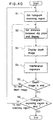
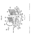
- Fig. 40 shows in more detail the exposure process shown in step S3 of Fig. 39, which step can, for example, be performed using an exposure apparatus as shown in Fig. 41.
- the exposure apparatus shown in Fig. 41 is first described before giving a full explanation of the exposure process depicted in Fig. 40.
- Fig. 41 shows an exposure apparatus comprising an image forming lens 238, a liquid crystal display 232 and a hologram dry plate 234.
- the liquid crystal display 232 is supported by a supporting arm 242 and can be moved in the Z and X directions by a Z-stage 246 and an X-stage 248 respectively, these being mounted on a base plate 235.
- the hologram dry plate 234 is supported by an arm 250 and can be moved in the X and Y directions by a further X-stage 252 and a Y-stage 254 as shown in Fig. 41.
- An image forming lens 238 is provided to converge the illumination light beam 256 so that, after passing through the liquid crystal display 232, it is focussed onto one of a multiplicity of micro segment hologram regions 236 on the hologram dry plate 234.
- step S1 one of the segment hologram regions 236 that are arrayed in matrix form over the hologram dry plate 234 is selected for exposure by aligning it with the optical axis 240 of the image forming lens 238.
- step S2 the distance in the Z direction between the liquid crystal display 232 and the hologram dry plate 234 is set to a distance Z 1 corresponding to the position of the projection plane of the zone to be first processed.
- step S3 the two-dimensional perspective image corresponding to the selected zone and the selected segment hologram region, which image is to be recorded in holographic form onto the selected micro segment hologram region 236, is loaded onto the liquid crystal display 232 and displayed.
- the illumination light 256 which has propagated through the image forming lens 238 and been converged thereby to form a light beam 257, passes through the liquid crystal display 232 on which the appropriate two-dimensional image is loaded and is modulated thereby.
- the thus modulated beam 257 then converges onto the selected segment hologram region 236 where it interferes with a coherent reference light beam 258 which divergently illuminates the hologram dry plate via a beam expander 255.
- step S4 the selected segment hologram region 236 is exposed so as to produce a hologram formed from the interference between the illuminating light 256, which has passed through the appropriately loaded liquid crystal display 232, and the reference light 258.
- step S5 a check is made to establish whether there are further zones for which respective depth images are to be processed for the currently selected segment hologram region 236. If there are, then the process is returned to step S2, with the distance between the liquid crystal display 232 and the hologram dry plate 234 being set to a value Z n corresponding to the position of the projection plane of the next zone to be processed. If there are not, then the exposure of the currently selected segment hologram region 236 is complete and step S6 follows. For example, if there are three zones in the depth direction, as shown in Figs.
- the images corresponding to the zones are displayed in turn with respective distances Z 1 , Z 2 and Z 3 between the liquid crystal display 232 and the hologram dry plate 234, thereby executing three successive interference exposures which are mutually superimposed at the selected hologram region 236.
- step S6 it is established whether all the necessary segment hologram regions 236 have been exposed. If YES the process is complete. If NO then the process is returned to step S1 and a further one of the segment hologram regions is selected for exposure by aligning it with the optical axis 240 of the image forming lens 238. Subsequent steps S2, S3... are repeated until the exposures of all the required regions are finished.
- Fig. 43 shows the steps of this method.
- step S1 two-dimensional image data obtained by photographing an object with a CCD camera or the like are input.
- step S2 this two-dimensional image data is used to form the required three-dimensional image data.
- steps S3 to S6 correspond to steps S2 to S5 respectively of the method of Fig. 2 described above.
- Fig. 44 is illustrative of step S1 of Fig. 43.
- a CCD camera 260 driven by, for example, a television system is installed at a position corresponding to that of the hologram formation surface 34.
- the CCD camera 260 has an image forming lens 262 and an image forming surface 264.
- the CCD camera can be moved in the plane of the hologram forming surface 34 by an XY-stage 266.
- Objects 36, 38 and 40 positioned at different distances from the hologram formation surface 34 are photographed by the CCD camera 260 and the thus obtained two-dimensional images are supplied to a computer 16.
- Fig. 45 is further illustrative of how the two-dimensional images are obtained.
- the resulting images comprise the image information input to the process.
- a separate CCD camera 260 can be installed at each photographing point position, or a single CCD camera 260 can be used which is moved to each such position in turn.
- the centre of the image forming lens 262 is aligned with the relevant photographing point P ij (image input position).
- the optical axis of the image forming lens 262 is set so that it extends in the same direction at each of the photographing points P ij .
- the optical axis of the image forming lens 262 can be set to remain directed to a preselected object point for all the photographing positions.
- the interval between adjacent photographing points P ij is set so that a continuously changing view of the surface of the imaged object is seen when the reconstructed image is viewed by an observer from a succession of different viewpoints, this condition being familiar from conventional holographic stereogram generation.
- two-dimensional images are photographed from only some of the photographing points, skipping intermediate points. Missing two-dimensional images, corresponding to the skipped points, are then generated by computational interpolation performed on the basis of three-dimensional image data computed from the two-dimensional image data sets obtained directly from the photographs.
- Fig. 46 shows details of the two-dimensional image inputting process shown in Fig. 45.
- step S1 the two-dimensional image data are obtained by photographing adjacent two-dimensional images.
- step S2 the photograph camera interval is fetched. The processes in steps S1 and S2 are repeated.
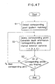
- Fig. 47 shows details of step S2 of Fig. 43 - a process of forming three-dimensional image data from extracted two-dimensional image data.
- respective corresponding points are detected from the two-dimensional image data by pattern matching of the image data obtained for two points.
- Depth information is calculated by using the principle of triangulation for the corresponding points, thereby producing the required three-dimensional data (X, Y, Z) of the corresponding points.
- Step S3 of Fig. 47 ensures that the process in step S2 is executed with respect to all of the corresponding points.
- Fig. 48 shows a hologram forming and image reconstruction method similar to that of Fig. 39 but with the three-dimensional image data formation being accomplished according to step S2 of Fig. 43 as just described.
Landscapes
- Physics & Mathematics (AREA)
- General Physics & Mathematics (AREA)
- Holo Graphy (AREA)
Description
- The present invention relates to the production of holograms for use in producing stereoscopic displays.
- A stereoscopic display is a display for enabling depth or thickness of a three-dimensional object to be easily visually appreciated. Stereoscopic display is useful for the display of a structural object designed by CAD, or the like, and for the display of a medical image or the like. A three-dimensional image is also more impressive than a two-dimensional display, and this makes stereoscopic displays desirable for amusement in an amusement park, a cinema, or the like.
- Various methods of stereoscopic display have been proposed. For example a hologram can be used. With holographic projection an observer can see a three-dimensional image without using special glasses. With holographic methods an object image is recorded by using light interference. Colour holograms giving an impression of depth have already been produced for static images. As another example computer graphics (CG) can allow a three-dimensional impression to be given to an observer. A virtual object having a three-dimensional structure is formed by CAD or the like. When the object is to be displayed on the computer screen as if viewed from a predetermined direction, a two-dimensional perspective image is calculated which takes account of appropriate reflection or shadows due to light. However, with computer graphics, the two-dimensional image does not convey a full stereoscopic impression.
- It is possible to display an image of a three-dimensional object, giving a stereoscopic impression, by using a holographic stereogram system.
Two-dimensional images of an object as viewed from various directions are produced by a computer graphics system, and respective holograms of those images are sequentially recorded as strip-like regions of a composite hologram, each having a microwidth in the horizontal direction and extending completely across the composite hologram in the vertical direction. - Computer generated composite holograms can be used, to reconstruct an image of a three-dimensional object, as described in an article by Toyohiko Yatagai in Applied Optics, Volume 15, No. 11, pages 2722 to 2728 (Nov. 1976). In this method a sequence of perspective projections of the three-dimensional object to be displayed is calculated and corresponding holograms are generated by a computer and arranged in sequence to synthesize a composite hologram.
- With such a conventional holographic stereogram, however, the surface at which the focal point of the observer's eyes is located may not coincide with the image position corresponding to parallax of the observer's eyes. Therefore the image is hard to see and fatigue results. Viewing such a displayed image having a large depth can be particularly burdensome on the eyes.
- A conventional hologram is recorded onto a film-like medium and it takes time to develop the image. Such delay may be inconvenient in a stereoscopic display system. Further, the contents of such a display cannot be rewritten.
- According to a first aspect of the present invention there is provided a method of producing a composite hologram for use in displaying a stereoscopic image of a three-dimensional subject located in an object space extending away from a hologram formation surface, the method comprising:
- a) obtaining three-dimensional coordinate data representing the said subject;
- b) defining a series of different spatial zones in the said object space, which zones span respective different ranges of distance from the hologram formation surface and contain respective different constituent parts of the said subject;
- c) deriving, from the said three-dimensional coordinate data, individual three-dimensional coordinate data sets representing respectively the said different constituent parts;
- d) defining for each of the said zones an individual projection plane;
- e) employing the individual three-dimensional coordinate data sets to compute, for each in turn of a multiplicity of preselected different viewpoints (Pi) arrayed over the said hologram formation surface, individual depth image data sets representing respective two-dimensional perspective images of the said different constituent parts, each as projected from the viewpoint concerned onto the individual projection plane defined for the zone containing the constituent part concerned; and
- f) employing the said depth image data sets in a process of forming a composite hologram made up of a multiplicity of different areal segments containing respective physical reproductions of individual segment holograms, each of which represents a two-dimensional image that is a combination of all the said perspective images pertaining to an individual one of the said different viewpoints (Pi), which reproductions are arrayed similarly to their respective corresponding viewpoints so that the composite hologram can be irradiated with a reproduction light beam to generate the desired stereoscopic image.
- According to a second aspect of the present invention there is provided an apparatus for producing a composite hologram for use in displaying a stereoscopic image of a three-dimensional subject located in an object space extending away from a hologram formation surface, which apparatus comprises:
- a) data-producing means for providing three-dimensional coordinate data representing the said subject;
- b) zone-defining means for defining a series of different spatial zones in the said object space, which zones span respective different ranges of distance from the hologram formation surface and contain respective different constituent parts of the said subject;
- c) data division means for deriving, from the said three-dimensional coordinate data, individual three-dimensional coordinate data sets representing respectively the said different constituent parts;
- d) projection-plane defining means operable to define for each of the said zones an individual projection plane;
- e) image-computing means for employing the said three-dimensional coordinate data sets to compute, for each in turn of a multiplicity of preselected different viewpoints (Pi) arrayed over the said hologram formation surface, individual depth image data sets representing respective two-dimensional perspective images of the said different constituent parts, each as projected from the viewpoint concerned onto the individual projection plane defined for the zone containing the constituent part concerned; and
- f) hologram-forming means for employing the said depth image data sets to form a composite hologram made up of a multiplicity of different areal segments containing respective physical reproductions of individual segment holograms, each of which represents a two-dimensional image that is a combination of all the said perspective images pertaining to an individual one of the said different viewpoints (Pi), which reproductions are arrayed similarly to their respective corresponding viewpoints so that the composite hologram can be irradiated with a reproduction light beam to generate the desired stereoscopic image.
- An embodiment of the present invention can be used to display a holographic image, for example a moving image, which can be viewed over long periods with little fatigue, the image being rewritten in a real-time manner.
- Three-dimensional coordinate data for use in an embodiment of the invention can for example be formed from two-dimensional image input data obtained by photographing an object with a CCD camera or the like.
- Embodiments of the invention can provide for hologram formation by multiple exposure of a recording medium to a plurality of two-dimensional images.
- In an embodiment of the invention, three-dimensional information to be expressed is divided in the depth direction, a plurality of three-dimensional zones, or regions, are set, zone data indicative of the three-dimensional information of the object to be displayed is formed for each zone and a plurality of depth image data sets comprising the two-dimensional image data is formed for each zone. The zones in the depth direction can be set such that one zone is set separately for each object to be expressed or such that one object is divided into a plurality of portions, each portion being assigned to a different zone. A projection plane which is parallel with the hologram forming surface is set in each region, and projection data of an object or objects as seen from the hologram formation surface, projected onto the two-dimensional plane, is produced as two-dimensional depth image data. For each of a multiplicity of segment hologram areas constituted as minimum units obtained by dividing the hologram formation surface into small areal segments, phase is calculated on the basis of two-dimensional pixels of which the depth image is constructed, so as to form a phase distribution constituting a segment hologram at the hologram formation surface. The phase distributions obtained for each of the plurality of depth images are added to each segment hologram at the same position, thereby obtaining a phase distribution at the hologram forming surface of a synthesized depth image.
- According to a further embodiment of the invention, the spatial phase distribution of a hologram is calculated from a plurality of two-dimensional depth images and the phase distribution obtained is expressed, i.e. reproduced in physical form, by means for spatially modulating the amplitude or phase of reproduction light. Rewritable stereoscopic display can be performed by optical wavefront conversion of a reproduction light beam. A plurality of depth images can be recorded in a multiplex manner on a recording medium by light interference exposure, to form each of the segment holograms. The segment holograms obtained are arranged and recorded on a hologram dry plate to form the composite hologram. Conventional holographic display techniques can then be applied to reproduce the holographic image from the recording medium. The fact that each segment hologram is based on a plurality of two-dimensional depth images, relating respectively to different depths of the object space, serves to reduce the difference between the distances at which an observer perceives an image to be located on the basis of eye parallax, on the one hand, and on the basis of eye focus (i.e. accommodation) on the other hand. Fatigue from viewing the holographic display can thus be decreased and, at the same time, a more natural three-dimensional representation is obtainable.
- Thus an embodiment of the present invention can enable a more natural stereoscopic display to be realized, as compared with conventional holographic stereograms. A CAD system can be used to electronically form holograms from virtual objects, so that stereoscopic images can be rewritten and displayed in a short time. Furthermore, colour stereoscopic displays can also be readily achieved.
- For a better understanding of the invention and to show how the same may be carried into effect, reference will now be made, by way of example, to the accompanying drawings, wherein:
- Fig. 1 is a flowchart showing a processing procedure, used to produce a stereoscopic display, in accordance with a first embodiment of the invention;
- Fig. 2 is a block diagram showing the construction of an apparatus for carrying out the procedure shown in Fig. 1;
- Fig. 3 is a diagram illustrating an expressing format of three-dimensional structural data in a CAD system;
- Fig. 4 is a diagram illustrating another expressing format of three-dimensional structural data in a CAD system;
- Fig. 5 is a flowchart showing details of a depth image forming step of Fig. 1;
- Fig. 6 is a perspective diagram showing division of an object space in a depth direction, there being a plurality of objects located in the space concerned;
- Fig. 7 shows diagrammatically a side view of the arrangement of Fig. 6;
- Fig. 8 is a perspective diagram showing division, in the depth direction, of an object space through which a single object extends;
- Fig. 9 shows a side view corresponding to Fig. 8;
- Fig. 10 is a diagram showing in side view a general example of depthwise division of an object space into different spatial zones, and the positions of projection planes which are defined respectively in those zones;
- Fig. 11 is a perspective diagram illustrating formation of two-dimensional projection data for separate objects located at different depths;
- Fig. 12 is a perspective diagram illustrating formation of two-dimensional projection data for a single object extending in the depth direction through a plurality of different depth zones;
- Fig. 13 is a diagram illustrating two-dimensional projection data formed in accordance with Fig. 11;
- Fig. 14 is diagram illustrating two-dimensional projection data formed in accordance with Fig. 12;
- Figs. 15A and 15B are diagrams showing how the positions of two objects relate to the projection data, when two-dimensional projection data is formed;
- Figs. 16A and 16B are diagrams corresponding respectively to Figs. 15A and 15B when the objects therein are rearranged;
- Fig. 17 is a diagram illustrating principles of calculating a phase distribution for a Fresnel-type hologram;
- Fig. 18 is a diagram illustrating formation of an image-type hologram;
- Fig. 19 is a diagram illustrating how a calculation range for a phase distribution is limited in the formation of an image-type hologram;
- Fig. 20 is a diagram showing the optical relationships, between a depth image display surface and a hologram formation surface used when calculating a phase distribution to display an enlarged three-dimensional image;
- Fig. 21 is a diagram illustrating a condition in which an image is enlarged to be twice the size of that in Fig. 20;
- Fig. 22 is a diagram showing the optical relationships between a depth image display surface and a hologram formation surface as a display position of a three-dimensional image is moved;
- Fig. 23 is a diagram showing changes in phase distribution calculation points at a hologram formation surface as an image display position moves;
- Fig. 24 is a diagram showing a perspective view of a stereoscopic display apparatus;
- Fig. 25 is a sectional diagram showing internal features of the apparatus of Fig. 24;
- Fig. 26 is a sectional diagram illustrating the structure of a liquid crystal display, of the transmission type, which may be used as a spatial light modulation device;
- Fig. 27 is a diagram illustrating phase modulation of reproduction light by three liquid crystal cells of Fig. 26;
- Fig. 28 is a schematic diagram of another stereoscopic display apparatus, using a spatial light modulation device of the reflection type;
- Fig. 29 is a more detailed diagram of the reflection-type spatial light modulation device of Fig. 28;
- Fig. 30 is a schematic diagram of a stereoscopic display apparatus using a spatial light modulation device of the optical writing type;
- Fig. 31 is a sectional diagram showing structural details of the optical writing type spatial light modulation device of Fig. 30;
- Fig. 32 is a perspective diagram of a stereoscopic display apparatus using an enlarging system;
- Fig. 33 is a perspective diagram of a stereoscopic display apparatus using a spatial light modulation device and having a refractive hologram for preventing transmission of zeroth order light;
- Fig. 34 is a schematic sectional diagram showing internal features of the apparatus of Fig. 30;
- Fig. 35 is a schematic diagram of a stereoscopic display apparatus for providing a colour stereoscopic display using two colour components (R and G);
- Fig. 36 is a schematic diagram of a stereoscopic display apparatus for providing a colour stereoscopic display using three colour components (R, G and B);
- Fig. 37 is a timing chart relating to time-divisional synthesis and display of the colour components in the apparatus of Fig. 36;
- Fig. 38 is a timing chart relating to positional division and simultaneous synthesis and display of the colour components in the apparatus of Fig. 36;
- Fig. 39 is a flowchart showing steps of a hologram forming method;
- Fig. 40 is a flowchart showing details of an exposure step in Fig. 39;
- Fig. 41 is a perspective diagram of an exposure apparatus used for performing the exposure step of Fig. 40;
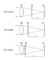
- Figs. 42A to 42C illustrate multiple exposure of two-dimensional images in a plurality of spatial zones for one segment hologram region of a hologram dry plate;
- Fig. 43 is a flowchart showing steps of a method of providing a stereoscopic display in which three-dimensional image data is formed from two-dimensional projection data obtained by photographing an object;
- Fig. 44 is a schematic diagram of apparatus for performing the method of Fig. 43;
- Fig. 45 is a perspective diagram illustrating arrangements for photographing objects;
- Fig. 46 is a flowchart showing details of a two-dimensional image input step of Fig. 43;
- Fig. 47 is a flowchart showing details of a three-dimensional data forming step of Fig. 43; and
- Fig. 48 is a flowchart of a processing procedure for forming a hologram by producing three-dimensional image data from two-dimensional projection data obtained by photographing an object.
- Fig. 1 illustrates a stereoscopic display method in which:
- In step S1, three-dimensional coordinate data constituting image information representing a subject consisting of an object or objects to be displayed, is formed from three-dimensional image data by a CAD system, or from two-dimensional data obtained by photographing the objects with a CCD camera or the like.
- In step S2, a plurality of depth images are formed by deriving 2-dimensional information from the three-dimensional image information. To produce the depth images, the space containing the objects to be displayed, as seen from a hologram formation surface, is divided up in the depth direction into a plurality of different spatial zones. Depth image data, as projected onto a projection plane set in each zone, each such plane being parallel to the hologram forming surface, is then formed.
- In step S3, a phase distribution at the hologram formation surface is calculated from the plurality of depth images.
- In step S4, the calculated phase distribution is reproduced physically so as to be expressed at the hologram formation surface. Irradiation of that surface with reproduction light then causes a three-dimensional image to be displayed as a result of optical wavefront conversion according to the expressed phase distribution.
- Fig. 2 shows the construction of an apparatus for performing the stereoscopic display method illustrated in Fig. 1. A three-dimensional image information forming section 10 is realized by, for example, a
CAD system 12. Three-dimensional image data representing objects to be displayed is formed by the three-dimensional image information forming section 10 and is given to a depthimage forming section 14, which derives therefrom a plurality of two-dimensional images located at different positions in the depth direction. The images formed by the depthimage forming section 14 are given to a phase distribution calculating section 15, which calculates a corresponding phase distribution at the hologram formation surface. The depthimage forming section 14 and the phase distribution calculating section 15 are realized by acomputer 16. The results of the calculation performed by the phase distribution calculating section 15 are given to a phasedistribution display section 18. A three-dimensional image is displayed by an opticalwavefront converting section 20. The phasedistribution display section 18 and the opticalwavefront converting section 20 form ahologram display apparatus 22. Alternatively a plurality of two-dimensional image data sets, formed by the depthimage forming section 14 for respective different positions in the depth direction, are given to ahologram exposing apparatus 24 and are used as a basis for recording holograms on a hologram dry plate, serving as a recording medium, by multiple exposure. A hologram can thus be formed as a fixed record. - Each processing step in Fig. 1 will now be described in more detail.
- The formation of three-dimensional image information is now described.
- An expressing format of three-dimensional image data in computer graphics can be used in the formation of the three-dimensional image information of an object to be stereoscopically displayed. For example, an
object 26 having three-dimensional structure may be separated into a set ofplanes 28 as shown in Fig. 3. Lists of contours or vertices of the planes are linked, thereby forming three-dimensional image data. - Alternatively, as shown in Fig. 4, the
object 26 may be expressed by a set of basic shapes 30-1, 30-2 and 30-3. Theobject 26 is expressed by using logicarithmetic operating expressions 32 defining the combination of basic shapes 30-1 to 30-3. Such expressing formats of the three-dimensional image data shown in Figs. 3 and 4 are widely used in the field of computer graphics. For example, in the present case, the three-dimensional image data can be produced from CAD data by using a CAD system as shown in Fig. 2. - Fig. 5 shows in more detail the Fig. 1 step of forming depth images.
- In step S1 of Fig. 5, the three-dimensional image data is divided into sets corresponding to a plurality of different spatial zones (regions) in the depth direction.
- In step S2 of Fig. 5, three-dimensional image data is formed for each zone (region).
- In step S3 of Fig. 5, two-dimensional depth image data is formed for each zone.
- The depth division of the three-dimensional image data will now be explained.
- Fig. 6 shows the depthwise division of an object space in which three
objects - A
hologram formation surface 34 is set at an arbitrary position relative to theobjects Spatial zones surface 34 and respectively containing theobjects hologram formation surface 34. A lateral direction of thehologram formation surface 34 is taken as an X axis, a vertical direction as a Y axis, and the depth direction as a Z axis in the object space. A two-dimensional coordinate system of independent two-dimensional coordinates Xh and Yh is set for thehologram formation surface 34. - Fig. 7 shows a side elevational view of Fig. 6. The
object 36 belongs to thezone 42 lying nearest to thehologram formation surface 34. Theobject 38 belongs to theadjacent zone 44. Theobject 40 belongs to thezone 46 lying furthest from thehologram formation surface 34. Figures 6 and 7 show a case in which it is possible to allocate separate objects into respective separate, non-overlapping, depth zones. In many cases, however, objects will overlap in the depth direction. - Fig. 8 shows zonal divisions for a
single object 70 which is extensive in the depth direction. In this case, thezones object 70 into three portions in the depth direction. - Fig. 9 shows a side view of the zonal divisions of Fig. 8.
- When the zonal divisions can be performed as shown in Figs. 6 to 9, each three-dimensional image data set is produced as a zonal data set which expresses the content of one zone. That is, in Figs. 6 and 7, after completion of the zonal division, independent three-dimensional image data is obtained for each
object - Fig. 10 shows the general depth division of three-dimensional image data. In this example, objects 90, 92, 94, 96 and 98 are arrayed in the depth direction in relation to the
hologram formation surface 34.Individual depth zones objects single background zone 86, furthest from thehologram formation surface 34, extends to infinity so as to contain theobjects hologram formation surface 34. - The formation of the two-dimensional depth images will now be described.
- When three-dimensional image data corresponding to the depth division has been formed, two-dimensional projection data is formed for each zone. In Fig. 7, projection planes 48, 50 and 52 are shown set for use respectively in forming the two-dimensional projection data sets for the three zones. These planes lie parallel to the
hologram formation surface 34 and pass through the respective geometrical centres of gravity of theobjects objects hologram formation surface 34, projected onto their corresponding projection planes 48, 50 and 52, the distances from theplanes hologram forming surface 34 having been previously obtained as Z1, Z2 and Z3 respectively. - In the case of Fig. 9 projection planes 72, 74 and 76 are set in a similar manner, these planes lying parallel to the
hologram formation surface 34 and passing through the geometrical centres of gravity of the respective cylindrical object portions 70-1, 70-2, and 70-3 in thezones - In the zonal division shown in Fig. 10, projection planes 100, 102 and 104 are set in a similar manner with respect to the
zones projection plane 106 is set for thebackground zone 86, at a distance Z4 in the depth direction from thehologram formation surface 34. The two-dimensional projection data of all of the objects in the background zone 86 (in this case theobjects 96 and 98) is formed in relation to their images as projected onto theplane 106. - Fig. 11 shows the principles of forming the two-dimensional depth images for the Fig. 6 arrangement. First, the
hologram formation surface 34 is divided up into small areal segments in a matrix-like manner, thereby formingsegment hologram areas 108 as minimum units of a composite hologram to be realized. The size of each of thesegment hologram areas 108 is set to about 1 mm or less in each of the vertical and horizontal directions. For the sake of simplicity, the segment hologram areas are shown larger than they would be in practice. Two-dimensional pixel information is formed as two-dimensional image data, related to theplanes segment hologram areas 108 used in turn as a point from which to view theobjects - For example, the three-dimensional pixel data representing the
object 36 is converted into plane pixel data representing that object as seen, projected onto theplane 48, from the viewpoint of the centralsegment hologram area 108 of thehologram formation surface 34. - The computation of such two-dimensional images at different depths is executed in a similar manner for the case in which a
single object 70 as shown in Fig. 8 is divided up between a plurality of zones (see Fig. 12). - Fig. 13 shows two-dimensional image data 36-1, 38-1 and 40-1 related respectively to the
planes segment hologram area 108 in Fig. 11. By superimposing those data, a synthesized complete two-dimensional depth image data set 54 can be obtained. - Fig. 14 shows the two-dimensional image data sets 70-1, 70-2 and 70-3 corresponding respectively to the
planes central segment hologram 108. In this case as well, by superimposing these three two-dimensional image data sets, a synthesized complete two-dimensional depth image 78, in this case two-dimensional image data 70-10 of a continuous cylindrical body, can be obtained. - The method whereby two-dimensional images of an object viewed from a plurality of different directions are formed on the basis of the three-dimensional data as mentioned above can be realized by using the three-dimensional display technique in conventional computer graphics. In this case, processing of hidden lines or hidden areas is also included so that the side surface which is seen is changed in accordance with the direction of observation.
- For example, as shown in Fig. 15A, when the
object 70 is located in front of anobject 68, a 'hidden area' process is executed whereby the part of the plane of theobject 68 obscured by theobject 70 is not displayed, the resulting image being as shown in Fig. 15B. Likewise, as shown in Fig. 16A, when theobject 70 is located behind theobject 68, the 'hidden area' process results in theobject 70 not being displayed at all since it is fully obscured by theobject 68, as indicated schematically in Fig. 16B. - With respect to shadows, when a two-dimensional depth image is formed, since two-dimensional image data is produced by radial projection from an origin constituted by the
segment hologram area 108 selected as a viewpoint, different images produced respectively for three different zones appear continuous upon observation, even when a single object is divided among three zones for display at different distances, as shown in Figs. 11 and 12. - When the size, in each of the vertical and horizontal directions, of the
segment hologram area 108 is 1 mm or less continuity is retained, even when two-dimensional image data is formed by shifting a viewpoint by an increment of a singlesegment hologram area 108 and even when the two-dimensional images displayed at different distances in the depth direction are mutually superimposed. The change in direction of observation of an object when viewed from one of thesegment hologram areas 108, as compared with the direction when viewed from an adjacentsegment hologram area 108, can be in a range from about 0.3 degree to 1 degree. Therefore, instead of moving the viewpoint from one to the next of a plurality ofsegment hologram areas 108 defined at regular intervals over thehologram formation surface 34, successive viewpoints may be set by changing the direction of observation in each case by a predetermined angle within a range from about 0.3 to 1 degree in both of the horizontal and vertical directions, using the centre of thehologram formation surface 34 as a starting point, and two-dimensional image data for each zone can be calculated for each viewpoint position determined in this way. - Calculation of the phase distribution is now described, the basic principles of hologram formation being explained first.
- A single laser beam is divided into two beams, one of which serves as a reference light beam and the other of which is used to irradiate an object. Some of the light of the latter beam is scattered back by the object to provide an object light flux. A hologram can be produced then by combining the reference light beam with the object light flux so that interference occurs between them at a hologram formation surface. If a wavefront of the reference light beam is represented by R·exp(jφr) and a wavefront of the object light flux is represented by O·exp (jφo), the exposure intensity IH of the resulting hologram is

- On development of the recorded hologram, changes in amplitudes and phases which are proportional to the exposure intensity IH of equation (1) contribute to the hologram. To form a hologram electrically, a spatial light modulation device such as a liquid crystal device or the like, which can change the amplitude and phase of light incident thereon, can be used. An image of the object can be reproduced for viewing by irradiating the hologram with a wavefront equivalent to that of the reference light beam. In the exposure intensity IH of equation (1), only the third term of the right-hand side contributes to the reproduction of the object light. Bearing this in mind, the light T transmitted through the hologram is given by the following equation:

- The first term on the right-hand side of equation (2) denotes that the wavefront from the object was reproduced. The second term on the right-hand side indicates a conjugate wave of the object light. From the above description, it will be understood that it is sufficient to calculate only the third term of the right-hand side of the equation (1) in the calculation of the phase distribution of a hologram.
- Fig. 17 shows the principles of the formation of a Fresnel-type hologram. If the reference light beam is a plane wave, its intensity is independent of location, so light intensity R can be ignored. Further, for a plane wave incident perpendicularly on the hologram surface, one may treat the phase as being everywhere φr = 0. When luminance (scattering degree) at a
certain sampling point 111 having coordinates (Xi, Yi, Zi) on anobject 110 is set to Ii, the exposure intensity IH of thehologram segment 108, being the minimum unit on thehologram forming surface 34, is

- For a Fresnel-type hologram as shown in Fig. 17 it is necessary to execute the calculations of equations (3) and (4) for the whole region of the
hologram formation surface 34, since the light irradiated from theobject 110 reaches the whole hologram. - On the other hand, for an image-type hologram as shown in Fig. 18, the image of the
object 110 is formed as areal image 114 at the position of thehologram formation surface 34 by animage forming lens 112. Therefore, as shown in Fig. 19, for example, light from asampling point 115 of thereal image 114 reaches only theportion 117 of thehologram formation surface 34, which portion is determined by avirtual opening 116. The region over which equations (3) and (4) need to be calculated is thus limited. - As an example, with respect to the central
segment hologram area 108 of the hologram formation surface shown in Fig. 11, each two-dimensional pixel of each of the two-dimensional depth image data sets obtained respectively from theobjects segment hologram 108 is then calculated as the sum of these exposure intensities obtained for the different zones. This is expressed by the following general equation with respect tozone numbers 1 to n.
- The size of a three-dimensional image displayed may be adjusted by the following method.
- Fig. 20 shows the
hologram formation surface 34 and a two-dimensional depth image display surface (projection plane) 118 which are separated by a predetermined distance. Animage 120 is shown projected onto theimage display surface 118. Theimage 120 is shown as an upward arrow. Acentre line 122 is shown extending in the Z-axis direction and passing through an origin point O on theimage display surface 118 and a point P0 on thehologram formation surface 34. The point P0 corresponds to one segment hologram. A point Pi corresponding to another segment hologram is shown above the point P0. The phase distribution at the point P0 is obtained from all of the sampling points of theimage 120 on the basis of the equations (3) and (4). Similarly, the phase distribution at the point Pi can be obtained from all of the sampling points of theimage 120. Theimage 120 appears different when seen from P0 as compared with Pi, the difference being due only to parallax. When the two-dimensional images of the depthimage display surface 118 are processed for each of the different points P0 and Pi on thehologram formation surface 34, the point Pi is displayed about the origin O, relative to P0, by only an angle θi. If theimage 120 is to be enlarged (or reduced), it is enlarged (or reduced) on the depthimage display surface 118 around the origin O as a centre, and the phases at the points P0 and Pi are calculated on the basis of the result of the enlargement (or reduction). - Fig. 21 shows a situation in which the
image 120 of Fig. 20 is enlarged by a factor of two to obtain an image 120-1. In this case also, the angle between the lines from the origin O to the points P0 and Pi respectively is θi, being unchanged. No contradiction occurs in the continuity of the parallax between the image seen from the point P0 and the image seen from the point Pi. It is desirable that the origin O of theimage 120 is set to a sharp edge portion on the object such that it can be always seen at the same position even when the viewpoint position is changed on thehologram formation surface 34. - Adjustment of the distance, from the hologram formation surface, at which a three-dimensional image is to be displayed can be achieved by the following method.
- Fig. 22 illustrates a change in the distance of a depth image display surface (projection plane), used to display an image 120-1, from the
hologram formation surface 34. First, it is assumed that the image 120-1 on the depth image display surface 118-1, located at a distance L in the depth direction from thehologram formation surface 34, is processed for the different points P0 and Pi on thehologram formation surface 34. In this case, the angular displacement of the point Pi from the point P0, about the centre of the image 120-1, is just an angle θi. When the depth image display surface moves from the position 118-1 to a more distant position 118-2, through a depthwise distance of ΔL, the calculation point Pi for the phase distribution is changed to Pi', so as to maintain the angle θi at the same value. The linear displacement Δd of this calculation point in the phase distribution calculation is in this instance
- Fig. 23 shows changes of four calculation points P1 to P4 distributed around the central phase distribution calculation point (segment hologram) P0. A case in which the image display surface is moved away from the
hologram formation surface 34 is shown at the right-hand side of Figure 23, while the left-hand side shows a case in which the image display surface is moved nearer. When the image display surface is moved nearer, the peripheral calculation points P1 to P4 approach one another more closely. When the image display surface is moved further away, the peripheral calculation points P1 to P4 are displaced radially outwardly and the distances between the calculation points increase. A two-dimensional depth image as seen from a position between the adjacent calculation points can be obtained by image interpolation. The phase distribution relating to the interpolation calculation point is calculated from the interpolation image, thereby maintaining the continuity of the reconstructed three-dimensional image in the case where the display surface was moved further away from the hologram formation surface. - Fig. 24 shows a hologram display apparatus for expressing the calculated phase distribution in physical form, as a composite hologram, and for displaying a three-dimensional image by irradiation of the composite hologram with a reproduction light beam. A spatial
light modulation device 130 for electrically forming the composite hologram is provided at the front of an apparatusmain body 128. Ahood 132 is also provided to shield the zeroth order light transmitted through thedevice 130. - Fig. 25 shows internal structure of the Fig. 24 apparatus. A
laser light source 134, which functions as a point light source, acollimating mirror 136 and acontroller 138 are disposed in the main body of the apparatus. Thecontroller 138 gives the calculated phase distribution to the spatiallight modulation device 130. A spherical wave originating as a point light source from thelaser light source 134 is converted into a parallel reproduction light beam (i.e. collimated) by reflection at thecollimating mirror 136 and is directed onto the spatiallight modulation device 130, thereby causing a three-dimensional image 135 to be reconstructed. The part of the collimated light beam which passes directly through the spatiallight modulation device 130 as a zeroth order component is blocked by thehood 132. - In a preferred embodiment, the
laser light source 134 is a small semiconductor laser with a spectral bandwidth of a few nanometres or less, which is capable of reconstructing a clear three-dimensional image. Any wavelength in the visible range can be used. It is, however, necessary to consider the wavelength of the light source, used for reconstruction, when calculating the hologram phase distribution. For example, it is possible to use a semiconductor laser which emits a red light beam whose wavelength is of the order of 600 nm, or one which emits a green light beam whose wavelength is of the order of 500 nm, or one which emits a blue light beam whose wavelength is of the order of 400 nm. - In case of a Fresnel-type hologram with the
object 110 positioned away from thehologram formation surface 34 as shown in Fig. 17, as the distance increases, the hologram (phase distribution) becomes more sensitive to the colour distribution over the spectral bandwidth of the reproduction light. In such a case, it is desirable to use a semiconductor laser having a narrow output bandwidth. - On the other hand, in the case of an image type hologram with the
image 114 located near thehologram formation surface 34 as shown in Fig. 18, the hologram is relatively insensitive to the colour distribution over the spectral bandwidth of the reproduction light. Therefore, a clear reproduction image can be obtained even when the spectral bandwidth of the source is relatively broad. In this case, it is possible to use a halogen lamp or the like, whose spectral bandwidth is about 10 nm, instead of a laser source. - Although a spherical wave is directly emitted from the
laser light source 134 in Fig. 25, it is also possible to construct the apparatus in such a manner that a laser beam is passed through an objective lens and a pin hole, or such that a laser beam is transmitted through an optical fibre to provide light which disperses from an output end of the fibre. - Fig. 26 shows a spatial
light modulation device 130, for use in an embodiment of the present invention, in which a liquid crystal display of the transmitting type is used. An input surface is provided by one side of a glass substrate 340, on the other side of which a uniformtransparent electrode 344 is disposed. Branched transparent electrodes 346-1 to 346-n form display segments and are arranged on an inner face of a glass substrate 342 at an output side of the device. Liquidcrystal orientation films transparent electrodes 344 and 346-1 to 346-n but separated therefrom respectively by insulatinglayers liquid crystal 360 is disposed between theorientation films reproduction light beam 362 is thus locally modulated in accordance with the control voltages applied. - Fig. 27 shows details of the phase modulation with respect to three of the pixels of the liquid crystal display as an example. Reproduction light beams 362-1 to 362-3 of the same phase, for example plane waves, enter from the left side into pixels 366-1 to 366-3. These pixels are driven in accordance with respective different phase states (so as to have different refractive indices) so that relative phase deviations exist between the outgoing light beams 364-1 to 364-3 as a result of their different optical path-lengths in the respective liquid crystal pixels 366-1 to 366-3.
- Ideally, it is desirable that any phase in a range from 0 to 2π can be expressed, which range corresponds to an optical distance of a full wavelength. However, even when the phase is expressed discretely, by multivalue levels, the desired phase distribution can be expressed approximately within a practical range. The thickness d of the liquid crystal layer is selected so as to satisfy conditions such that the product An x d, of the thickness d and the maximum refractive index change Δn which can be induced by the applied voltage, is equal to one wavelength λ of the reproduction light. To accurately express the phase distribution and to obtain a clearly reproduced three-dimensional image, it is necessary to limit the liquid crystal cell size to the order of a wavelength, using a liquid crystal display having a high resolution.
- Fig. 28 shows another stereoscopic display apparatus, for use in an embodiment of the invention, in which a reflecting-type spatial
light modulation device 130 is used. Thedevice 130 is provided in themain body 128 of the apparatus and electronically expresses (i.e. forms a physical reproduction of) a hologram having the phase distribution calculated by thecontroller 138. A reproduction light beam from thelaser light source 134 is reflected by amirror 140 and is further reflected by ahalf mirror 142 so as to enter the reflecting type spatiallight modulation device 130. Modulated light from themodulation device 130 passes through thehalf mirror 142, thereby displaying a three-dimensional image. - As shown in Fig. 29, in the reflection-
type modulation device 130 the reproduction light first enters a reflection-typeliquid crystal display 144 at one side of the device, is reflected by a reflectingsurface 146 at the opposite side, traverses thedisplay 144 once more, and is then emitted from the device. Since reproduction light passes through the liquid crystal display twice in such a reflection-type modulation device (as compared with only once in a transmission-type liquid crystal modulation device) the thickness of the liquid crystal layer needed to obtain a given phase change can be reduced by one half. It should be noted that in this embodiment a liquid crystal of the homogeneous orientation type is used so that its polarization is preserved. - Fig. 30 shows another embodiment of a stereoscopic display apparatus. In this embodiment the information of the calculated phase distribution is optically written and reproduced. A spatial
light modulation device 148, in which phase distribution information can be written optically by a laser beam from alight scanning section 145, is provided in themain body 128 of the apparatus. When phase distribution information is written into the spatiallight modulation device 148 by the laser beam from thelight scanning section 145, thecontroller 138 controls themodulation device 148 so that it provides the same conditions as in the reflection-type device 130 shown in Fig. 29. Thus, the laser beam from thelaser light source 134 is reflected by themirror 140 and thehalf mirror 142 and is incident on the left side of the spatiallight modulation device 148 as a reproduction light beam. The image is then displayed via projection through thehalf mirror 142 to the observer. - Fig. 31 shows internal structure of the optically writable spatial
light modulation device 148 of Fig. 30. Atransparent electrode 154, aphotoconductive layer 156 and alight shielding layer 158 are arranged on one side of aglass substrate 150, the other side of which receives a writinglight beam 170. Adielectric mirror 160 is provided inwardly of thelight shielding layer 158. Aglass substrate 152 is provided, on the side of the device which is opposite to that of thesubstrate 150, for receiving and re-emitting areproduction light beam 172. Atransparent electrode 155 is provided on thesubstrate 150. Aliquid crystal layer 165 is arranged between insulatingfilms transparent electrode 155 and thedielectric mirror 160. - During operation of the spatial
light modulation device 148 of Fig. 31, when the writinglight beam 170 is first incident on thephotoconductive layer 156, the resistance value of that layer drops where the light intensity is large. Since the resistance value of thephotoconductive layer 156 changes, while the driving voltage is kept constant, the voltage which is applied across the corresponding part of theliquid crystal panel 165 through thedielectric mirror 160 changes locally by an amount corresponding to the resistance value change. When the voltage which is applied across part of the liquid crystal changes, as mentioned above, the refractive index changes locally. When the incidentreproduction light beam 172 is reflected by thedielectric mirror 160 and is returned, the reproduction light becomes amodulation light beam 174 carrying phase modulation information. - Fig. 32 shows another stereoscopic display apparatus for use in an embodiment of the invention. In this embodiment, a
reproduction light beam 180 enters the spatiallight modulation device 130, which uses a transmission-type liquid crystal display or the like to express the calculated phase distribution, and is modulated thereby. The modulated light beam from the spatiallight modulation device 130 is enlarged by a projectionoptical system 176 and is projected onto ahologram screen 178, thereby enabling a three-dimensional image to be observed over thevisual field 182 corresponding to an angular visibility range θ. - Fig. 33 shows another embodiment of a stereoscopic display apparatus. In this embodiment a hood for preventing the zeroth order light component being displayed can be dispensed with. A refracting body for suppressing the emission of the zeroth order light is integrated with the spatial
light modulation device 184 in the apparatusmain body 128. - As shown in Fig. 34, in the stereoscopic display apparatus of Fig. 33 a spherical wave from the
laser light source 134 is reflected by thecollimating mirror 136 and directed onto the spatiallight modulation device 184, integrated with the refracting body, at an angle of incidence equal to or larger than the critical angle for the refracting body. The zeroth order light is therefore totally internally reflected, thereby preventing zeroth order light from being emitted. A hood to block out the zeroth order light is therefore not required. - To display colour images, it is sufficient that the formation of the three-dimensional image information in step S1 of Fig. 1, the formation of the depth image in step S2, and the calculation of the phase distribution in step S3, are executed for each spectral component, for example, for R, G and B components.
- Fig. 35 shows an embodiment of a colour stereoscopic display apparatus for producing a two-colour display, the apparatus comprising two of the stereoscopic display apparatuses described above. A spatial
light modulation device 200 is driven in accordance with the phase distribution calculated with respect to, for example, the R component by acontroller 226. A spatiallight modulation device 202 is driven in accordance with the phase distribution calculated with respect to, for example, the G component. Respective reproduction light beams fromlaser light sources light modulation devices shutters collimating lenses R component image 228 and a three-dimensionalG component image 230. TheG component image 230 is reflected by ahalf mirror 220 and is seen by theeyes 224 of the observer. At the same time, theR component image 228 passes through thehalf mirror 220 and enters theeyes 224. Consequently, the observer can see a synthetic colour three-dimensional image in which theG component image 230 is superimposed on theR component image 228. - Fig. 36 shows another colour stereoscopic display apparatus for use in an embodiment of the invention. In this embodiment the phase distribution is calculated for each of the R, G and B components to enable a synthesized colour image to be displayed. Three stereoscopic display apparatuses are used. Thus, in addition to the two display apparatuses used in the embodiment of Fig. 35, a
laser light source 210, ashutter 215 and acollimating lens 219 are provided to act as a display system for the B component. An additional spatiallight modulation device 204, driven in accordance with the phase distribution calculated with respect to the B component, is also provided. Further, ahalf mirror 222 is added for combining the B component image from the spatiallight modulation device 204 with the R and G component images. A synthesized three-dimensional colour image, formed from the R, G and B components shown by arrows, can thus be observed by theeyes 224 of the observer. - Fig. 37 shows a timing chart of driving signals ER, EG and EB for time-divisionally displaying the RGB components by opening or closing the
shutters controller 226 illustrated in Fig. 36. The driving signals ER, EG and EB are generated so as to be repeated at intervals T of 1/30 second and so have relative timing delays of T/3. In the case of the embodiment of Fig. 35, with only the components R and G, the timing deviation between the two signals ER and EG can be set to T/2. - Fig. 38 shows a timing chart of another driving method suitable for use with the embodiments of Figs. 35 and 36. In this case, the shutters are opened in unison at intervals of T = 1/30 second and three-dimensional images of two or three colour components are simultaneously displayed at the appropriate positions, thereby synthesizing the required colour image.
- A method of forming a hologram by exposure is now described with reference to Figs. 39 to 42.
- Fig. 39 shows a method of manufacturing a hologram on a hologram dry plate or the like. In this method, steps S1 and S2 are fundamentally the same as those of the method of Fig. 1, but subsequent steps differ therefrom.
- Instead of calculating the phase distribution, as in step S3 of the method of Fig. 1, in step S3 of the present method, the two-dimensional image data of the perspective projections of each object present in a given zone, as viewed from respective different viewpoints corresponding to respective segment hologram areas and projected onto the projection plane defined for the zone concerned, are directly used to generate an interference pattern to which a hologram dry plate or the like is exposed. The two-dimensional image data of each perspective projection is loaded in turn on a liquid crystal display or the like. Exposure is accomplished by interference between two light beams, one produced by irradiating the liquid crystal display with an illumination light beam and the second being a reference light beam which is arranged to interfere with the illumination light beam subsequent to the latter's modulation by the two-dimensional image data forming the perspective projection then loaded on the liquid crystal display.
- After completion of the exposure, a developing process is executed in step S4.
- A dry plate hologram dry plate resulting from this process can be placed into a display apparatus and irradiated with a reproduction light beam so that the beam becomes modulated, thereby generating a wavefront determined by the phase distribution recorded on the hologram and serving to display the corresponding stereoscopic image (step S5).
- Fig. 40 shows in more detail the exposure process shown in step S3 of Fig. 39, which step can, for example, be performed using an exposure apparatus as shown in Fig. 41. The exposure apparatus shown in Fig. 41 is first described before giving a full explanation of the exposure process depicted in Fig. 40.
- Fig. 41 shows an exposure apparatus comprising an
image forming lens 238, aliquid crystal display 232 and a hologramdry plate 234. Theliquid crystal display 232 is supported by a supportingarm 242 and can be moved in the Z and X directions by a Z-stage 246 and an X-stage 248 respectively, these being mounted on abase plate 235. The hologramdry plate 234 is supported by anarm 250 and can be moved in the X and Y directions by a further X-stage 252 and a Y-stage 254 as shown in Fig. 41. Animage forming lens 238 is provided to converge theillumination light beam 256 so that, after passing through theliquid crystal display 232, it is focussed onto one of a multiplicity of microsegment hologram regions 236 on the hologramdry plate 234. - The exposure process according to the flowchart of Fig. 40 will now be described with reference to the apparatus of Fig. 41.
- In step S1, one of the
segment hologram regions 236 that are arrayed in matrix form over the hologramdry plate 234 is selected for exposure by aligning it with theoptical axis 240 of theimage forming lens 238. - In step S2, the distance in the Z direction between the
liquid crystal display 232 and the hologramdry plate 234 is set to a distance Z1 corresponding to the position of the projection plane of the zone to be first processed. - In step S3, the two-dimensional perspective image corresponding to the selected zone and the selected segment hologram region, which image is to be recorded in holographic form onto the selected micro
segment hologram region 236, is loaded onto theliquid crystal display 232 and displayed. Theillumination light 256, which has propagated through theimage forming lens 238 and been converged thereby to form alight beam 257, passes through theliquid crystal display 232 on which the appropriate two-dimensional image is loaded and is modulated thereby. The thus modulatedbeam 257 then converges onto the selectedsegment hologram region 236 where it interferes with a coherentreference light beam 258 which divergently illuminates the hologram dry plate via abeam expander 255. - Thus, in step S4, the selected
segment hologram region 236 is exposed so as to produce a hologram formed from the interference between the illuminating light 256, which has passed through the appropriately loadedliquid crystal display 232, and thereference light 258. - In step S5, a check is made to establish whether there are further zones for which respective depth images are to be processed for the currently selected
segment hologram region 236. If there are, then the process is returned to step S2, with the distance between theliquid crystal display 232 and the hologramdry plate 234 being set to a value Zn corresponding to the position of the projection plane of the next zone to be processed. If there are not, then the exposure of the currently selectedsegment hologram region 236 is complete and step S6 follows. For example, if there are three zones in the depth direction, as shown in Figs. 42A, 42B and 42C, the images corresponding to the zones are displayed in turn with respective distances Z1, Z2 and Z3 between theliquid crystal display 232 and the hologramdry plate 234, thereby executing three successive interference exposures which are mutually superimposed at the selectedhologram region 236. - In step S6 it is established whether all the necessary
segment hologram regions 236 have been exposed. If YES the process is complete. If NO then the process is returned to step S1 and a further one of the segment hologram regions is selected for exposure by aligning it with theoptical axis 240 of theimage forming lens 238. Subsequent steps S2, S3... are repeated until the exposures of all the required regions are finished. - A method of forming the three-dimensional image data from photographing objects using a camera is now described with reference to Figs. 43 to 47.
- Fig. 43 shows the steps of this method.
- In step S1, two-dimensional image data obtained by photographing an object with a CCD camera or the like are input.
- In step S2, this two-dimensional image data is used to form the required three-dimensional image data.
- Subsequent steps S3 to S6 correspond to steps S2 to S5 respectively of the method of Fig. 2 described above.
- Fig. 44 is illustrative of step S1 of Fig. 43. A
CCD camera 260 driven by, for example, a television system is installed at a position corresponding to that of thehologram formation surface 34. TheCCD camera 260 has animage forming lens 262 and animage forming surface 264. The CCD camera can be moved in the plane of thehologram forming surface 34 by an XY-stage 266.Objects hologram formation surface 34 are photographed by theCCD camera 260 and the thus obtained two-dimensional images are supplied to acomputer 16. - Fig. 45 is further illustrative of how the two-dimensional images are obtained.
Objects hologram formation surface 34. The resulting images comprise the image information input to the process. To obtain photographs from each of the photographing points Pij, aseparate CCD camera 260 can be installed at each photographing point position, or asingle CCD camera 260 can be used which is moved to each such position in turn. For each photograph, the centre of theimage forming lens 262 is aligned with the relevant photographing point Pij (image input position). The optical axis of theimage forming lens 262 is set so that it extends in the same direction at each of the photographing points Pij. Alternatively, the optical axis of theimage forming lens 262 can be set to remain directed to a preselected object point for all the photographing positions. The interval between adjacent photographing points Pij is set so that a continuously changing view of the surface of the imaged object is seen when the reconstructed image is viewed by an observer from a succession of different viewpoints, this condition being familiar from conventional holographic stereogram generation. It is sufficient to set such an interval so as to provide an angular separation of about 0.3 to 1 degree between successive viewpoints. To provide a natural stereoscopic impression when the hologram is to be observed from a succession of different viewpoints, at least some hundreds of photographing points Pij are necessary in the horizontal direction and at least some tens of such points in the vertical direction. - In the case where it is difficult to arrange or move the camera or cameras to all of the desired photographing points, two-dimensional images are photographed from only some of the photographing points, skipping intermediate points. Missing two-dimensional images, corresponding to the skipped points, are then generated by computational interpolation performed on the basis of three-dimensional image data computed from the two-dimensional image data sets obtained directly from the photographs.
- Fig. 46 shows details of the two-dimensional image inputting process shown in Fig. 45.
- In step S1, the two-dimensional image data are obtained by photographing adjacent two-dimensional images.
- In step S2, the photograph camera interval is fetched. The processes in steps S1 and S2 are repeated.
- Fig. 47 shows details of step S2 of Fig. 43 - a process of forming three-dimensional image data from extracted two-dimensional image data. In order to form three-dimensional image data in this case, respective corresponding points are detected from the two-dimensional image data by pattern matching of the image data obtained for two points. Depth information is calculated by using the principle of triangulation for the corresponding points, thereby producing the required three-dimensional data (X, Y, Z) of the corresponding points. Step S3 of Fig. 47 ensures that the process in step S2 is executed with respect to all of the corresponding points. In the detection of the corresponding points in step S1 of Fig. 47, in addition to a method equivalent to observation by two eyes, using the two-dimensional images obtained by photographing from two points, precision can be further improved by using a method equivalent to observation by three eyes, using the two-dimensional images obtained by photographing from three points. On the other hand, as a method of directly obtaining depth information without detecting corresponding points, for example, it can be sufficient to measure distances by a rangefinder using a laser beam. The processes after the three-dimensional image data is formed from the two-dimensional image information photographed by the camera are substantially the same as those in the embodiment of Fig. 1 using the three-dimensional data of the CAD system.
- Fig. 48 shows a hologram forming and image reconstruction method similar to that of Fig. 39 but with the three-dimensional image data formation being accomplished according to step S2 of Fig. 43 as just described.
Claims (38)
- A method of producing a composite hologram for use in displaying a stereoscopic image of a three-dimensional subject (36, 38, 40) located in an object space extending away from a hologram formation surface (34), the method comprising:a) obtaining three-dimensional coordinate data representing the said subject;b) defining a series of different spatial zones (42, 44, 46) in the said object space, which zones span respective different ranges of distance from the hologram formation surface and contain respective different constituent parts (36, 38, 40) of the said subject;c) deriving, from the said three-dimensional coordinate data, individual three-dimensional coordinate data sets representing respectively the said different constituent parts;d) defining for each of the said zones (42, 44, 46) an individual projection plane (48, 50, 52);e) employing the individual three-dimensional coordinate data sets to compute, for each in turn of a multiplicity of preselected different viewpoints (Pi) arrayed over the said hologram formation surface (34), individual depth image data sets representing respective two-dimensional perspective images of the said different constituent parts, each as projected from the viewpoint concerned onto the individual projection plane defined for the zone containing the constituent part concerned; andf) employing the said depth image data sets in a process of forming a composite hologram made up of a multiplicity of different areal segments containing respective physical reproductions of individual segment holograms, each of which represents a two-dimensional image that is a combination of all the said perspective images pertaining to an individual one of the said different viewpoints (Pi), which reproductions are arrayed similarly to their respective corresponding viewpoints so that the composite hologram can be irradiated with a reproduction light beam to generate the desired stereoscopic image.
- A method according to claim 1, wherein at least two of the said different constituent parts (70-1, 70-2) are respective different portions of a single object (70).
- A method according to claim 1 or 2, wherein at least one of the said different constituent parts comprises a plurality of separate objects (96,98).
- A method as claimed in claim 1, wherein the said spatial zones are defined so that they contain respective separate objects that together constitute the said subject.
- A method according to claim 1, 2, 3 or 4, wherein that one of the said spatial zones which is the furthest from the hologram formation surface is a background zone (86) that extends to infinity.
- A method according to any preceding claim, wherein the projection plane (48, 50, 52) for each zone (42, 44, 46) is defined so that it contains the centre of gravity of the constituent part (36, 38, 40) located in the zone concerned.
- A method according to any preceding claim, wherein the said individual segment holograms are phase holograms.
- A method according to claim 7, wherein the composite hologram is formed on light modulating means for spatially modulating the amplitude of such a reproduction light beam in accordance with the phase distribution of each individual segment hologram.
- A method according to any preceding claim, wherein the said three-dimensional coordinate data representing the said subject is computed from two-dimensional image information obtained by photographing the subject.
- A method according to claim 9, wherein the said three-dimensional coordinate data representing the said subject is obtained by photographing the subject from a multiplicity of different photographing positions (Pij) arrayed over the said hologram formation surface (34).
- A method according to claim 10, wherein two-dimensional image information relating to the subject as viewed from a location between two of the said photographing positions is obtained, by computational interpolation, from the two-dimensional image information obtained by photographing the subject from the said two photographing positions.
- A method according to claim 10 or 11, wherein the photographing is performed by a camera device (260) which is moved to each of the different photographing positions in turn.
- A method according to claim 10 or 11, wherein the photographing is performed by individual camera devices arranged respectively at the different photographing positions.
- A method according to claim 12 or 13, wherein the photographing is performed in the same direction at each of the different photographing positions.
- A method according to claim 12 or 13, wherein the photographing of the constituent part of the said subject in each of the said zones is performed, at each of the different photographing positions, in a direction towards a predetermined point, in the said object space, that is the same for each of the different photographing positions.
- A method according to any preceding claim, wherein the computation of the said depth image data sets involves effective enlargement of the said perspective images.
- A method according to any one of claims 1 to 15, wherein the computation of the said depth image data sets involves effective reduction in size of the said perspective images.
- A method according to any preceding claim, wherein the composite hologram is formed by computing the characteristics of the said individual segment holograms and then physically reproducing them at the hologram formation surface (34).
- A method according to any preceding claim, wherein the composite hologram is formed on an optical modulation device (130) such that the said reproduction light beam can be transmitted thereby to generate the desired image.
- A method according to claim 19, wherein the said optical modulation device (130) includes a liquid crystal layer (360) controlled by application of control voltages to electrodes (346-1 to 346-n), mounted adjacent to the liquid crystal layer, so as to bring about local changes in the refractive index of the liquid crystal.
- A method according to any one of claims 1 to 18, wherein the composite hologram is formed on an optical modulation device such that the said reproduction light beam can be reflected thereby to generate the desired image.
- A method according to claim 21, wherein the said optical modulation device (148) includes a liquid crystal layer (165) which is controlled via local changes in the resistance of a photoconductive layer (156) that is arranged adjacent to the liquid crystal layer (165), which local changes are produced by control of a further light beam (170) incident on the photoconductive layer (156).
- A method according to any one of claims 1 to 18, wherein the composite hologram is formed by fixedly recording the said individual segment holograms sequentially on respective different areas (236) of a hologram recording medium (234), the different areas being arrayed similarly to the said respective viewpoints.
- A method according to claim 23, wherein each of the said individual segment holograms is recorded by exposing the corresponding area (236) of the recording medium (234) in turn to different hologram components which correspond respectively to the said perspective images computed for the viewpoint corresponding to the individual hologram concerned.
- A method according to claim 24, wherein each of the said hologram components is produced by:positioning an image display panel (232) parallel to the hologram recording medium (234) and at a distance therefrom that is equal to the distance, from the said hologram formation surface, of the individual projection plane corresponding to the perspective image concerned;causing the display panel (232) to display the perspective image concerned;directing an illumination light beam (257) via the display panel(232), so as to be modulated by the displayed image, onto that one of the said different areas (236) at which the individual hologram concerned is to be recorded; anddirecting a reference light beam (258) onto the said one area (236) so as to interfere there with the modulated illumination light beam.
- A method according to any preceding claim, wherein each of the individual projectiin planes (48, 50, 52) is parallel to the said hologram formation surface.
- A method according to any preceding claim, wherein each individual projection plane (48, 50, 52) is defined so as to be within the spatial zone for which that plane is defined.
- A method according to any preceding claim, followed by a step of irradiating the composite hologram with a reproduction light beam so as to generate the desired stereoscopic image (135).
- A method of generating a colour stereoscopic image, which method comprises producing, by a method according to any one of claims 1 to 27, an individual composite hologram (200, 202, 204) for each colour component (R, G, B) of which the colour stereoscopic image is to be made up, irradiating each such composite hologram with a reproduction light beam of the colour component for which that hologram was produced, and combining resulting light rays emanating from the individual composite holograms (200, 202, 204) to form the desired colour stereoscopic image.
- An apparatus for producing a composite hologram for use in displaying a stereoscopic image of a three-dimensional subject (36, 38, 40) located in an object space extending away from a hologram formation surface (34), which apparatus comprises:a) data-producing means for providing three-dimensional coordinate data representing the said subject;b) zone-defining means for defining a series of different spatial zones (42, 44, 46) in the said object space, which zones span respective different ranges of distance from the hologram formation surface and contain respective different constituent parts (36, 38, 40) of the said subject;c) data division means for deriving, from the said three-dimensional coordinate data, individual three-dimensional coordinate data sets representing respectively the said different constituent parts;d) projection-plane defining means operable to define for each of the said zones (42, 44, 46) an individual projection plane (48, 50, 52);e) image-computing means for employing the said three-dimensional coordinate data sets to compute, for each in turn of a multiplicity of preselected different viewpoints (Pi) arrayed over the said hologram formation surface (34), individual depth image data sets representing respective two-dimensional perspective images of the said different constituent parts, each as projected from the viewpoint concerned onto the individual projection plane defined for the zone containing the constituent part concerned; andf) hologram-forming means for employing the said depth image data sets to form a composite hologram made up of a multiplicity of different areal segments containing respective physical reproductions of individual segment holograms, each of which represents a two-dimensional image that is a combination of all the said perspective images pertaining to an individual one of the said different viewpoints (Pi), which reproductions are arrayed similarly to their respective corresponding viewpoints so that the composite hologram can be irradiated with a reproduction light beam to generate the desired stereoscopic image.
- An apparatus according to claim 30, wherein the said data-producing means are adapted to compute the said three-dimensional coordinate data from two-dimensional image information obtained by photographing the said subject concerned.
- An apparatus according to claim 30 or 31, wherein the said hologram-forming means are adapted to form the composite hologram by computing the characteristics of the said individual segment holograms and then physically reproducing them at the hologram formation surface (34).
- An apparatus according to claim 30, 31 or 32 wherein the said hologram-forming means include an optical modulation device (130), on which the said composite hologram is formed when the apparatus is in use, such that the said reproduction light beam can be transmitted by that device to generate the desired image.
- An apparatus according to claim 33, wherein the said optical modulation device (130) includes a liquid crystal layer (360) and means for controlling the device by applying control voltages to electrodes (346-1 to 346-n), mounted adjacent to the liquid crystal layer, so as to bring about local changes in the refractive index of the liquid crystal.
- An apparatus according to claim 30, 31 or 32, wherein the said hologram-forming means include an optical modulation device, on which the said composite hologram is formed when the apparatus is in use, such that the said reproduction light beam can be reflected by that device to generate the desired image.
- An apparatus according to claim 35, wherein the said optical modulation device (148) includes a liquid crystal layer (165) and means for controlling the device, via local changes in the resistance of a photoconductive layer (156) that is arranged adjacent to the liquid crystal layer (165), by directing a further light beam (170) onto the photoconductive layer (156).
- An apparatus according to claim 30 or 31, wherein the said hologram-forming means are adapted to record each of the said individual segment holograms in turn by exposing a corresponding individual area (236) of a hologram recording medium (234) to different hologram components which correspond respectively to the said perspective images computed for the viewpoint corresponding to the individual segment hologram concerned.
- An apparatus according to claim 37, wherein the said hologram-forming means include an image display panel and first and second light sources and are operable to produce each of the said hologram components by:causing the display panel (232), positioned at a distance from the hologram recording medium (234) that is equal to the distance, from the said hologram formation surface, of the individual projection plane corresponding to the perspective image concerned, to display the perspective image concerned;directing an illumination light beam (257) from the first light source via the display panel (232), so as to be modulated by the displayed image, onto that one of the corresponding individual areas (236) at which the individual segment hologram concerned is to be recorded; anddirecting a reference light beam (258) from the second light source onto the said one individual area (236) so as to interfere there with the modulated illumination light beam.
Applications Claiming Priority (2)
| Application Number | Priority Date | Filing Date | Title |
|---|---|---|---|
| JP222588/92 | 1992-08-21 | ||
| JP22258892A JP3238755B2 (en) | 1992-08-21 | 1992-08-21 | Hologram creation and stereoscopic display method and stereoscopic display device |
Publications (3)
| Publication Number | Publication Date |
|---|---|
| EP0589558A2 EP0589558A2 (en) | 1994-03-30 |
| EP0589558A3 EP0589558A3 (en) | 1994-06-08 |
| EP0589558B1 true EP0589558B1 (en) | 1997-10-29 |
Family
ID=16784826
Family Applications (1)
| Application Number | Title | Priority Date | Filing Date |
|---|---|---|---|
| EP93306161A Expired - Lifetime EP0589558B1 (en) | 1992-08-21 | 1993-08-04 | Stereoscopic display method and display apparatus |
Country Status (5)
| Country | Link |
|---|---|
| US (4) | US5644414A (en) |
| EP (1) | EP0589558B1 (en) |
| JP (1) | JP3238755B2 (en) |
| CA (1) | CA2103950C (en) |
| DE (1) | DE69314900T2 (en) |
Families Citing this family (68)
| Publication number | Priority date | Publication date | Assignee | Title |
|---|---|---|---|---|
| EP0759255B1 (en) * | 1995-03-08 | 2001-05-02 | Koninklijke Philips Electronics N.V. | Three-dimensional image display system |
| JPH08262369A (en) * | 1995-03-24 | 1996-10-11 | Komatsu Ltd | Three-dimensional stereoscopic display and its production |
| KR100414629B1 (en) * | 1995-03-29 | 2004-05-03 | 산요덴키가부시키가이샤 | 3D display image generation method, image processing method using depth information, depth information generation method |
| JP2000506998A (en) | 1996-03-15 | 2000-06-06 | レティナル ディスプレイ ケイマン リミティッド | Method and apparatus for viewing images |
| US6821457B1 (en) | 1998-07-29 | 2004-11-23 | Science Applications International Corporation | Electrically switchable polymer-dispersed liquid crystal materials including switchable optical couplers and reconfigurable optical interconnects |
| US5942157A (en) | 1996-07-12 | 1999-08-24 | Science Applications International Corporation | Switchable volume hologram materials and devices |
| US6867888B2 (en) * | 1996-07-12 | 2005-03-15 | Science Applications International Corporation | Switchable polymer-dispersed liquid crystal optical elements |
| JPH10178564A (en) * | 1996-10-17 | 1998-06-30 | Sharp Corp | Panorama image generator and recording medium |
| DK0921449T3 (en) * | 1997-11-20 | 2001-08-06 | Europ Economic Community | Computer controlled holographic method and device |
| US6088140A (en) * | 1998-02-05 | 2000-07-11 | Zebra Imaging, Inc. | Segmented display system for large, continuous autostereoscopic images |
| US6330088B1 (en) * | 1998-02-27 | 2001-12-11 | Zebra Imaging, Inc. | Method and apparatus for recording one-step, full-color, full-parallax, holographic stereograms |
| US6266167B1 (en) | 1998-02-27 | 2001-07-24 | Zebra Imaging, Inc. | Apparatus and method for replicating a hologram using a steerable beam |
| US6608911B2 (en) * | 2000-12-21 | 2003-08-19 | Digimarc Corporation | Digitally watermaking holograms for use with smart cards |
| AU5460899A (en) | 1998-07-29 | 2000-02-21 | Digilens Inc. | In-line infinity display system employing one or more switchable holographic optical elements |
| US6115152A (en) * | 1998-09-14 | 2000-09-05 | Digilens, Inc. | Holographic illumination system |
| AU6519099A (en) | 1998-10-16 | 2000-05-08 | Digilens Inc. | Method and system for display resolution multiplication |
| AU1209100A (en) | 1998-10-16 | 2000-05-08 | Digilens Inc. | Holographic technique for illumination of image displays using ambient illumination |
| EP1008919A1 (en) * | 1998-12-09 | 2000-06-14 | Communauté Européenne (CE) | Computer assisted holographic method and apparatus for reproducing three-dimensional images |
| US6366370B1 (en) | 1998-12-30 | 2002-04-02 | Zebra Imaging, Inc. | Rendering methods for full parallax autostereoscopic displays |
| US6678078B1 (en) | 1999-01-07 | 2004-01-13 | Digilens, Inc. | Optical filter employing holographic optical elements and image generating system incorporating the optical filter |
| US6507419B1 (en) | 1999-03-23 | 2003-01-14 | Digilens, Inc. | Illumination system using optical feedback |
| US6504629B1 (en) | 1999-03-23 | 2003-01-07 | Digilens, Inc. | Method and apparatus for illuminating a display |
| US6195184B1 (en) | 1999-06-19 | 2001-02-27 | The United States Of America As Represented By The Administrator Of The National Aeronautics And Space Administration | High-resolution large-field-of-view three-dimensional hologram display system and method thereof |
| JP4371280B2 (en) * | 1999-07-09 | 2009-11-25 | 大日本印刷株式会社 | Method for creating hologram display |
| WO2001011895A1 (en) | 1999-08-04 | 2001-02-15 | Digilens, Inc. | Apparatus for producing a three-dimensional image |
| US6549308B1 (en) | 2000-01-11 | 2003-04-15 | Zebra Imaging, Inc. | Unibiased light field models for rendering and holography |
| US7151849B1 (en) | 2000-01-11 | 2006-12-19 | Zebra Imaging, Inc. | Efficient block transform including pre-processing and post processing for autostereoscopic displays |
| US6730442B1 (en) | 2000-05-24 | 2004-05-04 | Science Applications International Corporation | System and method for replicating volume holograms |
| AU2001280034A1 (en) * | 2000-07-26 | 2002-02-05 | Ben-Gurion University Of The Negev | Holograms of three-dimensional realistic objects recorded without wave interference |
| US6530662B1 (en) | 2000-09-19 | 2003-03-11 | Disney Enterprises, Inc. | System and method for enhancing the realism of a displayed image |
| US6424437B1 (en) | 2000-10-10 | 2002-07-23 | Digilens, Inc. | Projection display employing switchable holographic optical elements |
| GB0027103D0 (en) * | 2000-11-07 | 2000-12-20 | Secr Defence | Improved 3D display |
| US20040246334A1 (en) * | 2001-08-30 | 2004-12-09 | Dimitri Philippou | Image portrayal system |
| CA2364601A1 (en) * | 2001-12-03 | 2003-06-03 | Utar Scientific Inc. | Computer-assisted hologram forming method and apparatus |
| JP3895166B2 (en) * | 2001-12-17 | 2007-03-22 | 大日本印刷株式会社 | How to create a computer generated hologram |
| JP4133832B2 (en) * | 2002-01-16 | 2008-08-13 | 独立行政法人科学技術振興機構 | Color video holography playback device |
| US6844948B2 (en) * | 2002-03-27 | 2005-01-18 | Rabbit Tanaka Corporation Limited | Integral hologram revolving lamp and method for making same |
| US7619739B1 (en) | 2002-08-29 | 2009-11-17 | Science Applications International Corporation | Detection and identification of biological agents using Bragg filters |
| JP4412576B2 (en) * | 2002-10-16 | 2010-02-10 | 大日本印刷株式会社 | 3D micro pattern display |
| JP4316916B2 (en) * | 2003-04-04 | 2009-08-19 | 大日本印刷株式会社 | Computer-generated hologram |
| US6950173B1 (en) | 2003-04-08 | 2005-09-27 | Science Applications International Corporation | Optimizing performance parameters for switchable polymer dispersed liquid crystal optical elements |
| JP4189879B2 (en) * | 2003-08-08 | 2008-12-03 | インターナショナル・ビジネス・マシーンズ・コーポレーション | Generating apparatus, generating method, program, and recording medium |
| JP4845386B2 (en) * | 2004-02-09 | 2011-12-28 | 株式会社エヌ・ティ・ティ・ドコモ | Stereoscopic image display apparatus and stereoscopic image display method |
| DE102004009422A1 (en) * | 2004-02-24 | 2005-09-08 | Metronic Ag | Method and device for applying diffractive elements to surfaces |
| DE102004063838A1 (en) * | 2004-12-23 | 2006-07-06 | Seereal Technologies Gmbh | Method and apparatus for calculating computer generated video holograms |
| US7983787B2 (en) * | 2006-02-28 | 2011-07-19 | Alexander Garnett | Methods of making artistic sculpture and sculptures so made |
| DE102006062377B4 (en) * | 2006-12-19 | 2018-03-22 | Seereal Technologies S.A. | Method and holographic display device for reducing speckle |
| DE102006062376B4 (en) * | 2006-12-19 | 2018-03-22 | Seereal Technologies S.A. | Method and display device for reducing speckle |
| US7936489B2 (en) * | 2007-02-09 | 2011-05-03 | GM Global Technology Operations LLC | Holographic information display |
| DE102007007162A1 (en) * | 2007-02-09 | 2008-08-14 | GM Global Technology Operations, Inc., Detroit | Holographic information display |
| GB0718626D0 (en) * | 2007-05-16 | 2007-11-07 | Seereal Technologies Sa | Holograms |
| US8085010B2 (en) * | 2007-08-24 | 2011-12-27 | The Powerwise Group, Inc. | TRIAC/SCR-based energy savings device for reducing a predetermined amount of voltage using pulse width modulation |
| RU2378673C1 (en) * | 2008-04-03 | 2010-01-10 | Владимир Исфандеярович Аджалов | Image visualisation method and device to this end |
| KR101539668B1 (en) | 2008-06-26 | 2015-08-06 | 삼성전자주식회사 | 3 3-dimensional image display device and method using a hologram optical element |
| JP4637942B2 (en) * | 2008-09-30 | 2011-02-23 | 富士フイルム株式会社 | Three-dimensional display device, method and program |
| US8428340B2 (en) * | 2009-09-21 | 2013-04-23 | Microsoft Corporation | Screen space plane identification |
| JP2012003033A (en) * | 2010-06-17 | 2012-01-05 | Pioneer Electronic Corp | Modulation pattern generation method and holographic stereogram creation device |
| JP2012244396A (en) * | 2011-05-19 | 2012-12-10 | Sony Corp | Image processing apparatus, image processing method, and program |
| US20140009807A1 (en) * | 2012-07-05 | 2014-01-09 | Yuechao Pan | Method and apparatus for space division multiplexed color holographic display |
| JP2015087596A (en) * | 2013-10-31 | 2015-05-07 | アルプス電気株式会社 | Image processor |
| JP6285327B2 (en) * | 2014-09-08 | 2018-02-28 | マクセル株式会社 | Hologram data generation apparatus, hologram data generation method, and hologram data generation program |
| US10606242B2 (en) * | 2015-03-12 | 2020-03-31 | Canon Kabushiki Kaisha | Print data division apparatus and program |
| US10571862B1 (en) * | 2015-05-21 | 2020-02-25 | Real View Imaging Ltd. | Producing a computer generated holographic image |
| GB201718978D0 (en) * | 2017-11-16 | 2018-01-03 | Iq Structures Sro | Full parallax holograms |
| US10789723B1 (en) * | 2018-04-18 | 2020-09-29 | Facebook, Inc. | Image object extraction and in-painting hidden surfaces for modified viewpoint rendering |
| CN110826375B (en) * | 2018-08-10 | 2022-08-12 | 广东虚拟现实科技有限公司 | Display method, display device, terminal equipment and storage medium |
| TWI735202B (en) * | 2020-04-10 | 2021-08-01 | 鴻海精密工業股份有限公司 | Backlight module and holographic display device |
| GB2609679B (en) * | 2021-12-10 | 2023-08-02 | Envisics Ltd | Colour optimisation for direct view |
Family Cites Families (19)
| Publication number | Priority date | Publication date | Assignee | Title |
|---|---|---|---|---|
| FR1582104A (en) * | 1968-06-11 | 1969-09-26 | ||
| US3832027A (en) * | 1969-03-12 | 1974-08-27 | Bell Telephone Labor Inc | Synthetic hologram generation from a plurality of two-dimensional views |
| NL7114673A (en) * | 1970-10-30 | 1972-05-03 | ||
| DE2218384C3 (en) * | 1972-04-15 | 1980-03-20 | Philips Patentverwaltung Gmbh, 2000 Hamburg | Holographic process for producing a three-dimensional image from a series of two-dimensional images from different perspectives |
| NO138161C (en) * | 1975-06-03 | 1978-08-02 | Sentralinst For Ind Forskning | PROCEDURE FOR PREPARING A SYNTHETIC HOLOGRAM |
| US4421380A (en) * | 1980-10-06 | 1983-12-20 | Mcgrew Stephen P | Full-color hologram |
| GB2140170B (en) * | 1983-05-19 | 1987-01-28 | New Holographic Design | Improvements in or relating to holography |
| US4669812A (en) * | 1983-09-12 | 1987-06-02 | Hoebing John L | Method and apparatus for 3-D image synthesis |
| DE3506368A1 (en) * | 1985-02-22 | 1986-09-04 | ESG Elektronik-System-GmbH, 8000 München | Method and device for generating holograms |
| US4778262A (en) * | 1986-10-14 | 1988-10-18 | American Bank Note Holographics, Inc. | Computer aided holography and holographic computer graphics |
| US4834476A (en) * | 1987-03-31 | 1989-05-30 | Massachusetts Institute Of Technology | Real image holographic stereograms |
| US4964684A (en) * | 1988-12-28 | 1990-10-23 | John Iovine | Holographic image recording using liquid crystal |
| US5022727A (en) * | 1989-11-01 | 1991-06-11 | Advanced Holographic Imaging Technologies, Inc. | Method and apparatus for producing full color stereographic holograms |
| JPH0444085A (en) * | 1990-06-11 | 1992-02-13 | Toshio Honda | Method and device for forming hologram |
| US5117296A (en) * | 1990-07-17 | 1992-05-26 | Hoebing John L | Apparatus and synthetic holography |
| US5138471A (en) * | 1990-07-20 | 1992-08-11 | Mcgrew Stephen P | Holocomposer |
| US5347375A (en) * | 1991-11-26 | 1994-09-13 | Kabushiki Kaisha Toshiba | Computer-assisted holographic image formation technique which determines interference pattern data used to form the holographic |
| US5237433A (en) * | 1992-01-03 | 1993-08-17 | Haines Kenneth A | Methods of hologram construction using computer-processed objects |
| JP2999637B2 (en) * | 1992-10-14 | 2000-01-17 | 富士通株式会社 | Hologram information creation method |
-
1992
- 1992-08-21 JP JP22258892A patent/JP3238755B2/en not_active Expired - Fee Related
-
1993
- 1993-08-04 DE DE69314900T patent/DE69314900T2/en not_active Expired - Lifetime
- 1993-08-04 EP EP93306161A patent/EP0589558B1/en not_active Expired - Lifetime
- 1993-08-12 CA CA002103950A patent/CA2103950C/en not_active Expired - Fee Related
-
1995
- 1995-03-27 US US08/411,220 patent/US5644414A/en not_active Expired - Lifetime
- 1995-09-25 US US08/533,191 patent/US5570208A/en not_active Expired - Lifetime
-
1996
- 1996-06-18 US US08/668,368 patent/US5717509A/en not_active Expired - Lifetime
- 1996-06-21 US US08/667,366 patent/US5852504A/en not_active Expired - Lifetime
Also Published As
| Publication number | Publication date |
|---|---|
| EP0589558A2 (en) | 1994-03-30 |
| DE69314900D1 (en) | 1997-12-04 |
| EP0589558A3 (en) | 1994-06-08 |
| US5644414A (en) | 1997-07-01 |
| JPH0667591A (en) | 1994-03-11 |
| US5852504A (en) | 1998-12-22 |
| DE69314900T2 (en) | 1998-03-05 |
| JP3238755B2 (en) | 2001-12-17 |
| CA2103950C (en) | 1997-09-16 |
| US5570208A (en) | 1996-10-29 |
| US5717509A (en) | 1998-02-10 |
| CA2103950A1 (en) | 1994-02-22 |
Similar Documents
| Publication | Publication Date | Title |
|---|---|---|
| EP0589558B1 (en) | Stereoscopic display method and display apparatus | |
| EP0590913B1 (en) | Stereoscopic display method and apparatus | |
| US5138471A (en) | Holocomposer | |
| US7738151B2 (en) | Holographic projector | |
| EP0580353B1 (en) | Stereoscopic display apparatus and method | |
| EP0580354B1 (en) | Stereoscopic display apparatus and method | |
| US20050122549A1 (en) | Computer assisted hologram forming method and apparatus | |
| US20080138717A1 (en) | Color holographic optical element | |
| JP3338479B2 (en) | Hologram creation and stereoscopic display method and stereoscopic display device | |
| US6870651B2 (en) | Apparatus and method for generating a dynamic image | |
| US7057779B2 (en) | Holographic stereogram device | |
| US20020191237A1 (en) | Hologram forming melthod | |
| JP2778362B2 (en) | Hologram fabrication method | |
| JPH06266274A (en) | Formation of holographic stereoscopic hard copy and device | |
| JP3583634B2 (en) | Stereoscopic video display method and apparatus and recording medium recording the control method thereof | |
| JP2822798B2 (en) | Hologram fabrication method | |
| JP3324328B2 (en) | Holographic three-dimensional hard copy creation method and creation apparatus | |
| JPH0627864A (en) | Method and device for generating computer hologram | |
| JP3274811B2 (en) | 3D image projector | |
| JPH03249686A (en) | Holographic stereoscopic hard copy and its formation and device | |
| JPH10332917A (en) | Diffraction element panel and three-dimensional image display device composed of it | |
| JPH06118860A (en) | Color stereoscopic image display device | |
| JPH0511675A (en) | Method and apparatus for producing hologram | |
| LT5964B (en) | Method for production of holographic master - originals |
Legal Events
| Date | Code | Title | Description |
|---|---|---|---|
| PUAI | Public reference made under article 153(3) epc to a published international application that has entered the european phase |
Free format text: ORIGINAL CODE: 0009012 |
|
| AK | Designated contracting states |
Kind code of ref document: A2 Designated state(s): DE FR GB |
|
| PUAL | Search report despatched |
Free format text: ORIGINAL CODE: 0009013 |
|
| AK | Designated contracting states |
Kind code of ref document: A3 Designated state(s): DE FR GB |
|
| 17P | Request for examination filed |
Effective date: 19940721 |
|
| 17Q | First examination report despatched |
Effective date: 19951026 |
|
| GRAG | Despatch of communication of intention to grant |
Free format text: ORIGINAL CODE: EPIDOS AGRA |
|
| GRAH | Despatch of communication of intention to grant a patent |
Free format text: ORIGINAL CODE: EPIDOS IGRA |
|
| GRAH | Despatch of communication of intention to grant a patent |
Free format text: ORIGINAL CODE: EPIDOS IGRA |
|
| GRAA | (expected) grant |
Free format text: ORIGINAL CODE: 0009210 |
|
| AK | Designated contracting states |
Kind code of ref document: B1 Designated state(s): DE FR GB |
|
| PG25 | Lapsed in a contracting state [announced via postgrant information from national office to epo] |
Ref country code: FR Free format text: LAPSE BECAUSE OF FAILURE TO SUBMIT A TRANSLATION OF THE DESCRIPTION OR TO PAY THE FEE WITHIN THE PRESCRIBED TIME-LIMIT Effective date: 19971029 |
|
| REF | Corresponds to: |
Ref document number: 69314900 Country of ref document: DE Date of ref document: 19971204 |
|
| EN | Fr: translation not filed | ||
| PLBE | No opposition filed within time limit |
Free format text: ORIGINAL CODE: 0009261 |
|
| STAA | Information on the status of an ep patent application or granted ep patent |
Free format text: STATUS: NO OPPOSITION FILED WITHIN TIME LIMIT |
|
| 26N | No opposition filed | ||
| REG | Reference to a national code |
Ref country code: GB Ref legal event code: IF02 |
|
| PGFP | Annual fee paid to national office [announced via postgrant information from national office to epo] |
Ref country code: DE Payment date: 20100728 Year of fee payment: 18 |
|
| PGFP | Annual fee paid to national office [announced via postgrant information from national office to epo] |
Ref country code: GB Payment date: 20100811 Year of fee payment: 18 |
|
| GBPC | Gb: european patent ceased through non-payment of renewal fee |
Effective date: 20110804 |
|
| REG | Reference to a national code |
Ref country code: DE Ref legal event code: R119 Ref document number: 69314900 Country of ref document: DE Effective date: 20120301 |
|
| PG25 | Lapsed in a contracting state [announced via postgrant information from national office to epo] |
Ref country code: GB Free format text: LAPSE BECAUSE OF NON-PAYMENT OF DUE FEES Effective date: 20110804 |
|
| PG25 | Lapsed in a contracting state [announced via postgrant information from national office to epo] |
Ref country code: DE Free format text: LAPSE BECAUSE OF NON-PAYMENT OF DUE FEES Effective date: 20120301 |