EP0588930B1 - Verfahren und vorrichtung zum aufrechterhalten einer hohen gastemperatur in einem kraftwerk mit verbrennung im fliessbett unter druck - Google Patents
Verfahren und vorrichtung zum aufrechterhalten einer hohen gastemperatur in einem kraftwerk mit verbrennung im fliessbett unter druck Download PDFInfo
- Publication number
- EP0588930B1 EP0588930B1 EP92913467A EP92913467A EP0588930B1 EP 0588930 B1 EP0588930 B1 EP 0588930B1 EP 92913467 A EP92913467 A EP 92913467A EP 92913467 A EP92913467 A EP 92913467A EP 0588930 B1 EP0588930 B1 EP 0588930B1
- Authority
- EP
- European Patent Office
- Prior art keywords
- bed
- combustor
- tubes
- load operation
- outlets
- Prior art date
- Legal status (The legal status is an assumption and is not a legal conclusion. Google has not performed a legal analysis and makes no representation as to the accuracy of the status listed.)
- Expired - Lifetime
Links
- 238000000034 method Methods 0.000 title claims abstract description 9
- 239000007789 gas Substances 0.000 claims abstract description 20
- 239000000567 combustion gas Substances 0.000 claims abstract description 11
- 238000001816 cooling Methods 0.000 claims abstract description 7
- 239000003546 flue gas Substances 0.000 claims description 17
- UGFAIRIUMAVXCW-UHFFFAOYSA-N Carbon monoxide Chemical compound [O+]#[C-] UGFAIRIUMAVXCW-UHFFFAOYSA-N 0.000 claims description 6
- 238000002485 combustion reaction Methods 0.000 claims description 4
- 238000004140 cleaning Methods 0.000 claims description 3
- 238000007599 discharging Methods 0.000 claims description 3
- 239000002245 particle Substances 0.000 claims description 2
- 230000006978 adaptation Effects 0.000 claims 1
- 230000001105 regulatory effect Effects 0.000 claims 1
- 208000016791 bilateral striopallidodentate calcinosis Diseases 0.000 abstract 1
- 239000000428 dust Substances 0.000 description 5
- 239000002912 waste gas Substances 0.000 description 5
- JTJMJGYZQZDUJJ-UHFFFAOYSA-N phencyclidine Chemical class C1CCCCN1C1(C=2C=CC=CC=2)CCCCC1 JTJMJGYZQZDUJJ-UHFFFAOYSA-N 0.000 description 2
- 244000007645 Citrus mitis Species 0.000 description 1
- 235000002918 Fraxinus excelsior Nutrition 0.000 description 1
- NINIDFKCEFEMDL-UHFFFAOYSA-N Sulfur Chemical compound [S] NINIDFKCEFEMDL-UHFFFAOYSA-N 0.000 description 1
- 239000005864 Sulphur Substances 0.000 description 1
- 239000002956 ash Substances 0.000 description 1
- 230000000694 effects Effects 0.000 description 1
- 238000005192 partition Methods 0.000 description 1
- 239000002594 sorbent Substances 0.000 description 1
Images
Classifications
-
- F—MECHANICAL ENGINEERING; LIGHTING; HEATING; WEAPONS; BLASTING
- F23—COMBUSTION APPARATUS; COMBUSTION PROCESSES
- F23C—METHODS OR APPARATUS FOR COMBUSTION USING FLUID FUEL OR SOLID FUEL SUSPENDED IN A CARRIER GAS OR AIR
- F23C10/00—Fluidised bed combustion apparatus
- F23C10/16—Fluidised bed combustion apparatus specially adapted for operation at superatmospheric pressures, e.g. by the arrangement of the combustion chamber and its auxiliary systems inside a pressure vessel
-
- F—MECHANICAL ENGINEERING; LIGHTING; HEATING; WEAPONS; BLASTING
- F01—MACHINES OR ENGINES IN GENERAL; ENGINE PLANTS IN GENERAL; STEAM ENGINES
- F01K—STEAM ENGINE PLANTS; STEAM ACCUMULATORS; ENGINE PLANTS NOT OTHERWISE PROVIDED FOR; ENGINES USING SPECIAL WORKING FLUIDS OR CYCLES
- F01K23/00—Plants characterised by more than one engine delivering power external to the plant, the engines being driven by different fluids
- F01K23/02—Plants characterised by more than one engine delivering power external to the plant, the engines being driven by different fluids the engine cycles being thermally coupled
- F01K23/06—Plants characterised by more than one engine delivering power external to the plant, the engines being driven by different fluids the engine cycles being thermally coupled combustion heat from one cycle heating the fluid in another cycle
- F01K23/061—Plants characterised by more than one engine delivering power external to the plant, the engines being driven by different fluids the engine cycles being thermally coupled combustion heat from one cycle heating the fluid in another cycle with combustion in a fluidised bed
- F01K23/062—Plants characterised by more than one engine delivering power external to the plant, the engines being driven by different fluids the engine cycles being thermally coupled combustion heat from one cycle heating the fluid in another cycle with combustion in a fluidised bed the combustion bed being pressurised
-
- F—MECHANICAL ENGINEERING; LIGHTING; HEATING; WEAPONS; BLASTING
- F23—COMBUSTION APPARATUS; COMBUSTION PROCESSES
- F23C—METHODS OR APPARATUS FOR COMBUSTION USING FLUID FUEL OR SOLID FUEL SUSPENDED IN A CARRIER GAS OR AIR
- F23C10/00—Fluidised bed combustion apparatus
- F23C10/02—Fluidised bed combustion apparatus with means specially adapted for achieving or promoting a circulating movement of particles within the bed or for a recirculation of particles entrained from the bed
Definitions
- the present invention relates to a method and a device for maintaining a high gas temperature to a gas turbine in connection with partial-load operation of a PFBC plant, in which gas is fed out from a fluidizable bed in a combustor which also includes tubes for generating steam, the tubes being completely or partially covered by the fluidized bed in dependence on the degree of load.
- PFBC P ressurized Fucidised B ed C ombustion
- a varying part of the tubes which are to generate steam for a steam turbine in the plant will be covered by the fluidized bed in dependence on the degree of partial load.
- the tubes In case of full-load operation, the tubes are completely covered, and in case of partial-load operation they are partially covered.
- the non-covered tube portions cool the combustion gases which leave the bed at a temperature of about 850°C.
- a reduced temperature of the gases to the gas turbine entails, inter alia, a deteriorated efficiency of the plant, less good conditions for NO X reduction, and an increased CO content in the waste gases from the plant.
- the invention aims to provide a solution to the abovementioned problems and other problems associated therewith and is characterized in that hot combustion gases are discharged from outlets located at different levels in the combustor in dependence on the degree of partial load.
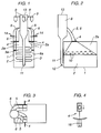
- Figure 1 is a view showing the principle of a PFBC power plant according to the invention
- Figure 2 is a side view of the same plant.
- Figures 3 and 4 show features of the invention.
- Figures 1 and 2 show a combustor 1 for a PFBC power plant, wherein the combustor 1 comprises a fluidizable bed 2 of a kind known per se (cf. EP 108 505).
- This bed 2 accomodates tubes 3 for cooling the bed 2, which generate steam for steam turbines.
- the tubes 3 are normally fully covered by the fluidized bed 2.
- the combustion gases leaving the bed 2 to a freeboard 2a above the bed surface have a high temperature, preferably 850°C.
- the bed level is lowered, parts of the tubes 3 thus being exposed such that portions of the tubes 3, tube portions 3a, will be located above the surface of the bed 2.
- Valve members 4 are arranged at the upper part of the combustion chamber in the combustor 1.
- two separate flue gas channels are provided. These consist primarily of a centrally arranged flue gas channel, a central channel 5, which may, per se, consist of and is suitably designed as several channels separated from each other.
- the central channel 5 is provided with a higher outlet 5a for flue gases from the freeboard 2a, which outlet 5a is located at a higher level in the combustor 1 than the tube portions 3a.
- Other channels for flue gases, side channels 6, are arranged adjacent to the walls of the combustor 1.
- These side channels 6 are provided at their lower part with lower outlets 6a for flue gases from the freeboard 2a, which lower outlets 6a are located at a lower level in the combustor 1 than the outlets 5a, namely at the side of the upper tube portions 3a. This means that the flue gases which are forced out from the combustor 1 via the side channels 6 do not pass the tube portions 3a to any major extent and consequently are not cooled by these tube portions 3a.
- valve members 4 are arranged such that the central channel 5 is open and the side channels 6 closed, which means that the flue gases which leave the bed surface, which in case of full load is located at a higher level than the tube portions 3a, are passed out via the higher outlet 5a to the central channel 5.
- the surface of the fluidized bed 2 is lowered, whereby tube portions 3a are exposed and will be positioned above the bed surface of the freeboard 2a.
- the valve members 4 are adjusted such that the central channel 5 is closed completely or partially in dependence on the degree of partial load, while at the same time the side channels 6 are opened completely or partially to a corresponding extent, in dependence on the degree of partial load, the whole of or part of the flue gas flow thus being discharged from the combustor 1 at the side of the tube portions 3a via the lower outlets 6a to the side channels 6. In this way, the flue gases are passed out at the side of the tube portions 3a, the cooling from these tube portions 3a thus being reduced or completely stopped.
- a double set of central channels 5 and side channels 6, one channel of each type being located along the long sides of the combustor 1, is used in the embodiment shown in Figure 1 in a version of a combustor 1 having rectangular cross section. Between the central channel 5 and the side channel 6 a partition 7 is arranged.
- the tube portions 3a cover a smaller area of the horizontal cross section area of the combustor 1 than that cross section area which is occupied by the other tubes 3 in the entire set of steam tubes in the bed 2.
- Both central channels 5 and side channels 6 open out into one (or more) coarse cleaner cyclones 8, in which dust is separated from the flue gases and removed via the cyclone leg 11. Dust in the cyclone leg 11 is returned to the bed, for example via a so-called L-valve 12, by means of which dust is injected into the bed 2. Cleaned flue gases are discharged from the cyclone 8 at outlets in the uppermost section 13 of the cyclone.
- beams such as U-beams 10
- U-beams 10 suitably arranged in a labyrinth to perform a coarse cleaning of the waste gases, coarser particles being captured by the labyrinth and returned to the bed.
- the coarse-cleaned waste gases are thereafter passed to the coarse cleaner cyclone 8.
- Figure 3 illustrates an embodiment with a combustor 1 designed with rectangular cross section, indicating a proposed location of the valve members 4.
- the flue gases are cleaned further by means of conventional dust separators, shown schematically in Figure 1 in the form of cyclones 9, adjacent the flue gas outlet from the coarse cleaner cyclone 8.
- NH3 may be injected for reducing NO x in flue gases.
- Sorbent for sulphur cleaning e.g. lime
- Sorbent for sulphur cleaning can also be injected through corresponding nozzles 14.
- the flow of waste gas from the bed 2 can thus be completely or partially passed by the upper tube portions 3a, which are exposed during partial-load operation, to the coarse cleaner cyclone 8.
- This coarse cleaner cyclone 8 returns more or less unburnt dust/ashes emanating from the bed 2 to the bed via the cyclone leg 11.
- Figure 4 illustrates how the valve member 4 is controlled from a drive member 16 positioned outside a partially shown pressure vessel wall in the pressure vessel which surrounds the combustor 1.
Landscapes
- Engineering & Computer Science (AREA)
- Chemical & Material Sciences (AREA)
- Combustion & Propulsion (AREA)
- Mechanical Engineering (AREA)
- General Engineering & Computer Science (AREA)
- Fluidized-Bed Combustion And Resonant Combustion (AREA)
Claims (8)
- Verfahren zur Aufrechterhaltung einer hohen Gastemperatur des zu einer Gasturbine gelieferten Gases bei Teillastbetrieb eines Kraftwerkes mit Verbrennung in einem unter Druck stehenden Wirbelbett, wobei Gas aus einem Wirbelbett (2) eines Combustors (1), der auch Rohre (3) zur Kühlung des Bettes (2) und zur Erzeugung von Dampf enthält, abgeführt wird, wobei die genannten Rohre (3) bei Vollast der Anlage vollständig im Bett (2) eingetaucht sind und bei Teillast der Anlage obere Abschnitte (3a) der Rohre frei über der Oberfläche des Bettes (2) liegen, dadurch gekennzeichnet, daß bei Teillast der Anlage die gesamten oder ein Teil der Verbrennungsgase über Kanäle (6) an den Seiten der freigelegten Rohrabschnitte (3a) aus dem Combustor (1) abgeführt werden/wird, wobei diese Rohrabschnitte (3a) vollständig oder teilweise von den Verbrennungsgasen umgangen werden, und daß bei Vollast der Anlage die Gase über Austrittsöffnungen (5a) abgeführt werden, die auf einem Niveau oberhalb der genannten Rohrabschnitte (3a) liegen.
- Verfahren nach Anspruch 1, dadurch gekennzeichnet, daß die Gase in einem Labyrinth aus U-Trägern (10) grob gereinigt werden, bevor sie den Combustor (1) verlassen.
- Verfahren nach Anspruch 2, dadurch gekennzeichnet, daß Partikel aus den Verbrennungsgasen, die während der Grobreinigung abgetrennt werden, dem Wirbelbett (2) wieder zugeführt werden.
- Verfahren gemäß einem oder mehreren der vorhergehenden Ansprüche, dadurch gekennzeichnet, daß die Austrittsöffnungen (5a), (6a) und die Zuordnung des Abgasstromes zu den zentralen Kanälen (5) beziehungsweise den Seitenkanälen (6) durch Ventilglieder (4) gesteuert werden, die in Abhängigkeit des Grades der Teillast geregelt werden.
- Vorrichtung zur Durchführung des Verfahrens zur Aufrechterhaltung einer hohen Gastemperatur des zu einer Gasturbine gelieferten Gases bei Teillastbetrieb eines Kraftwerkes mit Verbrennung in einem unter Druck stehenden Wirbelbett, wobei Gas aus einem Wirbelbett (2) eines Combustors (1), der auch Rohre (3) zur Kühlung des Bettes (2) und zur Erzeugung von Dampf enthält, abgeführt wird, wobei die genannten Rohre (3) bei Vollast der Anlage vollständig im Bett (2) eingetaucht sind und bei Teillast der Anlage obere Abschnitte (3a) der Rohre frei über der Oberfläche des Bettes (2) liegen, dadurch gekennzeichnet, daß Austrittsöffnungen auf verschiedenen Niveaus des Combustor zur Abführung der Verbrennungsgase aus dem Combustor angeordnet sind, und zwar untere Austrittsöffnungen (6a) an der Seite der oberen Abschnitte (3a) der Rohre und höhere Austrittsöffnungen (5a) auf einem Niveau oberhalb der höchstmöglichen Oberfläche des Bettes.
- Vorrichtung nach Anspruch 5, dadurch gekennzeichnet, daß Ventilglieder (4) angeordnet sind zum vollständigen oder teilweisen Öffnen beziehungsweise Schließen der verschiedenen Gasaustrittsöffnungen (5a, 6a) in Abhängigkeit des Grades der Teillast.
- Vorrichtung nach Anspruch 5, dadurch gekennzeichnet, daß die Austrittsöffnungen (5a, 6a) für Gaskanäle in mindestens einen Grobreinigungszyklon (8) münden.
- Vorrichtung nach Anspruch 7, dadurch gekennzeichnet, daß der Grobreinigungszyklon (8) oder dessen Zyklonleitung (11) mit dem Bettraum verbunden ist.
Applications Claiming Priority (3)
| Application Number | Priority Date | Filing Date | Title |
|---|---|---|---|
| SE9101901 | 1991-06-20 | ||
| SE9101901A SE9101901D0 (sv) | 1991-06-20 | 1991-06-20 | Saett vid pfbc-anlaeggning |
| PCT/SE1992/000425 WO1993000554A1 (en) | 1991-06-20 | 1992-06-15 | A method and a device for maintaining a high gas temperature in a pfbc power plant |
Publications (2)
| Publication Number | Publication Date |
|---|---|
| EP0588930A1 EP0588930A1 (de) | 1994-03-30 |
| EP0588930B1 true EP0588930B1 (de) | 1996-03-13 |
Family
ID=20383102
Family Applications (1)
| Application Number | Title | Priority Date | Filing Date |
|---|---|---|---|
| EP92913467A Expired - Lifetime EP0588930B1 (de) | 1991-06-20 | 1992-06-15 | Verfahren und vorrichtung zum aufrechterhalten einer hohen gastemperatur in einem kraftwerk mit verbrennung im fliessbett unter druck |
Country Status (9)
| Country | Link |
|---|---|
| US (1) | US5406785A (de) |
| EP (1) | EP0588930B1 (de) |
| JP (1) | JPH06508427A (de) |
| DE (1) | DE69209071T2 (de) |
| DK (1) | DK0588930T3 (de) |
| ES (1) | ES2087539T3 (de) |
| FI (1) | FI100551B (de) |
| SE (1) | SE9101901D0 (de) |
| WO (1) | WO1993000554A1 (de) |
Family Cites Families (8)
| Publication number | Priority date | Publication date | Assignee | Title |
|---|---|---|---|---|
| US3659559A (en) * | 1970-06-22 | 1972-05-02 | Foster Wheeler Corp | Fluidised bed burner control |
| US3863606A (en) * | 1973-07-25 | 1975-02-04 | Us Environment | Vapor generating system utilizing fluidized beds |
| DE3066241D1 (en) * | 1980-04-16 | 1984-03-01 | Bbc Brown Boveri & Cie | Steam power station with pressure-fired fluidised bed steam generator |
| DE3640377A1 (de) * | 1986-11-26 | 1988-06-09 | Steinmueller Gmbh L & C | Verfahren zur verbrennung von kohlenstoffhaltigen materialien in einem wirbelschichtreaktor und vorrichtung zur durchfuehrung des verfahrens |
| US4793292A (en) * | 1987-07-13 | 1988-12-27 | A. Ahlstrom Corporation | Circulating fluidized bed reactor |
| SE458955B (sv) * | 1987-10-20 | 1989-05-22 | Abb Stal Ab | Pfbc-kraftanlaeggning |
| US5022893A (en) * | 1990-03-01 | 1991-06-11 | Foster Wheeler Energy Corporation | Fluidized bed steam temperature enhancement system |
| EP1085055B1 (de) * | 1999-09-20 | 2004-10-20 | Ciba SC Holding AG | Azofarbstoff, Verfahren zu dessen Herstellung und dessen Verwendung zum Färben oder Bedrucken von hydrophoben Fasermaterialien |
-
1991
- 1991-06-20 SE SE9101901A patent/SE9101901D0/xx unknown
-
1992
- 1992-06-15 US US08/167,945 patent/US5406785A/en not_active Expired - Fee Related
- 1992-06-15 ES ES92913467T patent/ES2087539T3/es not_active Expired - Lifetime
- 1992-06-15 EP EP92913467A patent/EP0588930B1/de not_active Expired - Lifetime
- 1992-06-15 DK DK92913467.4T patent/DK0588930T3/da active
- 1992-06-15 DE DE69209071T patent/DE69209071T2/de not_active Expired - Fee Related
- 1992-06-15 WO PCT/SE1992/000425 patent/WO1993000554A1/en not_active Ceased
- 1992-06-15 JP JP5501240A patent/JPH06508427A/ja active Pending
-
1993
- 1993-12-17 FI FI935711A patent/FI100551B/fi active
Also Published As
| Publication number | Publication date |
|---|---|
| ES2087539T3 (es) | 1996-07-16 |
| DE69209071T2 (de) | 1996-10-24 |
| US5406785A (en) | 1995-04-18 |
| SE9101901D0 (sv) | 1991-06-20 |
| WO1993000554A1 (en) | 1993-01-07 |
| FI100551B (fi) | 1997-12-31 |
| DE69209071D1 (de) | 1996-04-18 |
| DK0588930T3 (da) | 1996-07-22 |
| EP0588930A1 (de) | 1994-03-30 |
| FI935711L (fi) | 1993-12-17 |
| FI935711A0 (fi) | 1993-12-17 |
| JPH06508427A (ja) | 1994-09-22 |
Similar Documents
| Publication | Publication Date | Title |
|---|---|---|
| EP0574176B1 (de) | Einen Wärmeaustauscher aufweisendes Wirbelbettreaktorsystem und -verfahren | |
| US5341766A (en) | Method and apparatus for operating a circulating fluidized bed system | |
| EP0365723B1 (de) | Wirbelschichtreaktor mit integriertem Rückführungswärmeaustauscher | |
| US5343830A (en) | Circulating fluidized bed reactor with internal primary particle separation and return | |
| CA1259859A (en) | Circulating fluidized bed reactor temperature control | |
| CA2393338C (en) | Cfb with controllable in-bed heat exchanger | |
| US6039008A (en) | Steam generator having an improved structural support system | |
| EP0682761B1 (de) | Methode und vorrichtung zur wärmegewinnung in einem wirbelbettreaktor | |
| US4552097A (en) | Steam generator with a stationary fluidized-bed hearth | |
| EP0413611B1 (de) | Verfahren und Anlage zur Regelung des Abdichtungswirkungsgrades gegen Rückströmung und des Rückführungsgrades in Wirbelschichtreaktoren | |
| CN1112996A (zh) | 有整体循环热交换器的加压流化床燃烧系统和方法 | |
| CA2062304A1 (en) | Fluidized bed combustion system and method having multiple furnace sections | |
| US5372096A (en) | Internal particle collecting cells for circulating fluid bed combustion | |
| US5242662A (en) | Solids recycle seal system for a fluidized bed reactor | |
| US5406785A (en) | Method and a device in a PFBC power plant | |
| US5772969A (en) | Method and apparatus for recovering heat in a fluidized bed reactor | |
| US5022893A (en) | Fluidized bed steam temperature enhancement system | |
| EP0243156A1 (de) | Wirbelschicht-Reaktor | |
| EP0398718B1 (de) | Dichtungssystem für Feststoffrückführung in einem Wirbelbettreaktor | |
| CA1309898C (en) | Fluidized bed reactor having an integrated recycle heat exchanger | |
| JPH0642941B2 (ja) | 一体型再循環熱交換器を有する流動床反応装置及びその操作方法 |
Legal Events
| Date | Code | Title | Description |
|---|---|---|---|
| PUAI | Public reference made under article 153(3) epc to a published international application that has entered the european phase |
Free format text: ORIGINAL CODE: 0009012 |
|
| 17P | Request for examination filed |
Effective date: 19931217 |
|
| AK | Designated contracting states |
Kind code of ref document: A1 Designated state(s): DE DK ES FR GB IT SE |
|
| 17Q | First examination report despatched |
Effective date: 19940914 |
|
| GRAH | Despatch of communication of intention to grant a patent |
Free format text: ORIGINAL CODE: EPIDOS IGRA |
|
| GRAH | Despatch of communication of intention to grant a patent |
Free format text: ORIGINAL CODE: EPIDOS IGRA |
|
| GRAA | (expected) grant |
Free format text: ORIGINAL CODE: 0009210 |
|
| AK | Designated contracting states |
Kind code of ref document: B1 Designated state(s): DE DK ES FR GB IT SE |
|
| REF | Corresponds to: |
Ref document number: 69209071 Country of ref document: DE Date of ref document: 19960418 |
|
| ET | Fr: translation filed | ||
| ITF | It: translation for a ep patent filed | ||
| REG | Reference to a national code |
Ref country code: ES Ref legal event code: BA2A Ref document number: 2087539 Country of ref document: ES Kind code of ref document: T3 |
|
| REG | Reference to a national code |
Ref country code: ES Ref legal event code: FG2A Ref document number: 2087539 Country of ref document: ES Kind code of ref document: T3 |
|
| REG | Reference to a national code |
Ref country code: DK Ref legal event code: T3 |
|
| GRAH | Despatch of communication of intention to grant a patent |
Free format text: ORIGINAL CODE: EPIDOS IGRA |
|
| PLBE | No opposition filed within time limit |
Free format text: ORIGINAL CODE: 0009261 |
|
| STAA | Information on the status of an ep patent application or granted ep patent |
Free format text: STATUS: NO OPPOSITION FILED WITHIN TIME LIMIT |
|
| 26N | No opposition filed | ||
| PGFP | Annual fee paid to national office [announced via postgrant information from national office to epo] |
Ref country code: DK Payment date: 19980612 Year of fee payment: 7 |
|
| PGFP | Annual fee paid to national office [announced via postgrant information from national office to epo] |
Ref country code: SE Payment date: 19990414 Year of fee payment: 8 |
|
| PGFP | Annual fee paid to national office [announced via postgrant information from national office to epo] |
Ref country code: GB Payment date: 19990609 Year of fee payment: 8 |
|
| PGFP | Annual fee paid to national office [announced via postgrant information from national office to epo] |
Ref country code: FR Payment date: 19990610 Year of fee payment: 8 |
|
| PG25 | Lapsed in a contracting state [announced via postgrant information from national office to epo] |
Ref country code: DK Free format text: LAPSE BECAUSE OF NON-PAYMENT OF DUE FEES Effective date: 19990615 |
|
| PGFP | Annual fee paid to national office [announced via postgrant information from national office to epo] |
Ref country code: DE Payment date: 19990618 Year of fee payment: 8 |
|
| PGFP | Annual fee paid to national office [announced via postgrant information from national office to epo] |
Ref country code: ES Payment date: 19990621 Year of fee payment: 8 |
|
| REG | Reference to a national code |
Ref country code: DK Ref legal event code: EBP |
|
| PG25 | Lapsed in a contracting state [announced via postgrant information from national office to epo] |
Ref country code: GB Free format text: LAPSE BECAUSE OF NON-PAYMENT OF DUE FEES Effective date: 20000615 |
|
| PG25 | Lapsed in a contracting state [announced via postgrant information from national office to epo] |
Ref country code: SE Free format text: LAPSE BECAUSE OF NON-PAYMENT OF DUE FEES Effective date: 20000616 Ref country code: ES Free format text: THE PATENT HAS BEEN ANNULLED BY A DECISION OF A NATIONAL AUTHORITY Effective date: 20000616 |
|
| GBPC | Gb: european patent ceased through non-payment of renewal fee |
Effective date: 20000615 |
|
| EUG | Se: european patent has lapsed |
Ref document number: 92913467.4 |
|
| PG25 | Lapsed in a contracting state [announced via postgrant information from national office to epo] |
Ref country code: FR Free format text: LAPSE BECAUSE OF NON-PAYMENT OF DUE FEES Effective date: 20010228 |
|
| REG | Reference to a national code |
Ref country code: FR Ref legal event code: ST |
|
| PG25 | Lapsed in a contracting state [announced via postgrant information from national office to epo] |
Ref country code: DE Free format text: LAPSE BECAUSE OF NON-PAYMENT OF DUE FEES Effective date: 20010403 |
|
| REG | Reference to a national code |
Ref country code: ES Ref legal event code: FD2A Effective date: 20020204 |
|
| PG25 | Lapsed in a contracting state [announced via postgrant information from national office to epo] |
Ref country code: IT Free format text: LAPSE BECAUSE OF NON-PAYMENT OF DUE FEES;WARNING: LAPSES OF ITALIAN PATENTS WITH EFFECTIVE DATE BEFORE 2007 MAY HAVE OCCURRED AT ANY TIME BEFORE 2007. THE CORRECT EFFECTIVE DATE MAY BE DIFFERENT FROM THE ONE RECORDED. Effective date: 20050615 |