EP0587834B1 - Vorrichtung zur messung einer distanz mittels ultraschall - Google Patents
Vorrichtung zur messung einer distanz mittels ultraschall Download PDFInfo
- Publication number
- EP0587834B1 EP0587834B1 EP93905145A EP93905145A EP0587834B1 EP 0587834 B1 EP0587834 B1 EP 0587834B1 EP 93905145 A EP93905145 A EP 93905145A EP 93905145 A EP93905145 A EP 93905145A EP 0587834 B1 EP0587834 B1 EP 0587834B1
- Authority
- EP
- European Patent Office
- Prior art keywords
- measurement tube
- reflector
- tube
- section
- measuring tube
- Prior art date
- Legal status (The legal status is an assumption and is not a legal conclusion. Google has not performed a legal analysis and makes no representation as to the accuracy of the status listed.)
- Expired - Lifetime
Links
- 238000005259 measurement Methods 0.000 claims description 12
- 238000000034 method Methods 0.000 claims description 3
- 229910001220 stainless steel Inorganic materials 0.000 claims description 2
- 239000010935 stainless steel Substances 0.000 claims description 2
- 238000002604 ultrasonography Methods 0.000 description 10
- 238000001514 detection method Methods 0.000 description 4
- 239000000463 material Substances 0.000 description 3
- 229920003023 plastic Polymers 0.000 description 3
- 239000004033 plastic Substances 0.000 description 3
- 230000005540 biological transmission Effects 0.000 description 2
- 230000008878 coupling Effects 0.000 description 2
- 238000010168 coupling process Methods 0.000 description 2
- 238000005859 coupling reaction Methods 0.000 description 2
- 229910000831 Steel Inorganic materials 0.000 description 1
- 229910052782 aluminium Inorganic materials 0.000 description 1
- XAGFODPZIPBFFR-UHFFFAOYSA-N aluminium Chemical compound [Al] XAGFODPZIPBFFR-UHFFFAOYSA-N 0.000 description 1
- 238000010276 construction Methods 0.000 description 1
- 238000005260 corrosion Methods 0.000 description 1
- 230000007797 corrosion Effects 0.000 description 1
- 230000000694 effects Effects 0.000 description 1
- 230000008030 elimination Effects 0.000 description 1
- 238000003379 elimination reaction Methods 0.000 description 1
- 230000007613 environmental effect Effects 0.000 description 1
- 239000007788 liquid Substances 0.000 description 1
- 239000002184 metal Substances 0.000 description 1
- 229910052751 metal Inorganic materials 0.000 description 1
- 239000004800 polyvinyl chloride Substances 0.000 description 1
- 239000010959 steel Substances 0.000 description 1
Images

Classifications
-
- G—PHYSICS
- G01—MEASURING; TESTING
- G01F—MEASURING VOLUME, VOLUME FLOW, MASS FLOW OR LIQUID LEVEL; METERING BY VOLUME
- G01F23/00—Indicating or measuring liquid level or level of fluent solid material, e.g. indicating in terms of volume or indicating by means of an alarm
- G01F23/30—Indicating or measuring liquid level or level of fluent solid material, e.g. indicating in terms of volume or indicating by means of an alarm by floats
- G01F23/64—Indicating or measuring liquid level or level of fluent solid material, e.g. indicating in terms of volume or indicating by means of an alarm by floats of the free float type without mechanical transmission elements
- G01F23/72—Indicating or measuring liquid level or level of fluent solid material, e.g. indicating in terms of volume or indicating by means of an alarm by floats of the free float type without mechanical transmission elements using magnetically actuated indicating means
-
- G—PHYSICS
- G01—MEASURING; TESTING
- G01B—MEASURING LENGTH, THICKNESS OR SIMILAR LINEAR DIMENSIONS; MEASURING ANGLES; MEASURING AREAS; MEASURING IRREGULARITIES OF SURFACES OR CONTOURS
- G01B17/00—Measuring arrangements characterised by the use of infrasonic, sonic or ultrasonic vibrations
-
- G—PHYSICS
- G01—MEASURING; TESTING
- G01F—MEASURING VOLUME, VOLUME FLOW, MASS FLOW OR LIQUID LEVEL; METERING BY VOLUME
- G01F23/00—Indicating or measuring liquid level or level of fluent solid material, e.g. indicating in terms of volume or indicating by means of an alarm
- G01F23/22—Indicating or measuring liquid level or level of fluent solid material, e.g. indicating in terms of volume or indicating by means of an alarm by measuring physical variables, other than linear dimensions, pressure or weight, dependent on the level to be measured, e.g. by difference of heat transfer of steam or water
- G01F23/28—Indicating or measuring liquid level or level of fluent solid material, e.g. indicating in terms of volume or indicating by means of an alarm by measuring physical variables, other than linear dimensions, pressure or weight, dependent on the level to be measured, e.g. by difference of heat transfer of steam or water by measuring the variations of parameters of electromagnetic or acoustic waves applied directly to the liquid or fluent solid material
- G01F23/296—Acoustic waves
- G01F23/2968—Transducers specially adapted for acoustic level indicators
-
- G—PHYSICS
- G01—MEASURING; TESTING
- G01F—MEASURING VOLUME, VOLUME FLOW, MASS FLOW OR LIQUID LEVEL; METERING BY VOLUME
- G01F23/00—Indicating or measuring liquid level or level of fluent solid material, e.g. indicating in terms of volume or indicating by means of an alarm
- G01F23/30—Indicating or measuring liquid level or level of fluent solid material, e.g. indicating in terms of volume or indicating by means of an alarm by floats
- G01F23/64—Indicating or measuring liquid level or level of fluent solid material, e.g. indicating in terms of volume or indicating by means of an alarm by floats of the free float type without mechanical transmission elements
- G01F23/68—Indicating or measuring liquid level or level of fluent solid material, e.g. indicating in terms of volume or indicating by means of an alarm by floats of the free float type without mechanical transmission elements using electrically actuated indicating means
-
- G—PHYSICS
- G01—MEASURING; TESTING
- G01S—RADIO DIRECTION-FINDING; RADIO NAVIGATION; DETERMINING DISTANCE OR VELOCITY BY USE OF RADIO WAVES; LOCATING OR PRESENCE-DETECTING BY USE OF THE REFLECTION OR RERADIATION OF RADIO WAVES; ANALOGOUS ARRANGEMENTS USING OTHER WAVES
- G01S15/00—Systems using the reflection or reradiation of acoustic waves, e.g. sonar systems
- G01S15/02—Systems using the reflection or reradiation of acoustic waves, e.g. sonar systems using reflection of acoustic waves
- G01S15/06—Systems determining the position data of a target
- G01S15/08—Systems for measuring distance only
-
- G—PHYSICS
- G01—MEASURING; TESTING
- G01S—RADIO DIRECTION-FINDING; RADIO NAVIGATION; DETERMINING DISTANCE OR VELOCITY BY USE OF RADIO WAVES; LOCATING OR PRESENCE-DETECTING BY USE OF THE REFLECTION OR RERADIATION OF RADIO WAVES; ANALOGOUS ARRANGEMENTS USING OTHER WAVES
- G01S7/00—Details of systems according to groups G01S13/00, G01S15/00, G01S17/00
- G01S7/52—Details of systems according to groups G01S13/00, G01S15/00, G01S17/00 of systems according to group G01S15/00
- G01S7/52004—Means for monitoring or calibrating
-
- G—PHYSICS
- G10—MUSICAL INSTRUMENTS; ACOUSTICS
- G10K—SOUND-PRODUCING DEVICES; METHODS OR DEVICES FOR PROTECTING AGAINST, OR FOR DAMPING, NOISE OR OTHER ACOUSTIC WAVES IN GENERAL; ACOUSTICS NOT OTHERWISE PROVIDED FOR
- G10K11/00—Methods or devices for transmitting, conducting or directing sound in general; Methods or devices for protecting against, or for damping, noise or other acoustic waves in general
- G10K11/02—Mechanical acoustic impedances; Impedance matching, e.g. by horns; Acoustic resonators
- G10K11/025—Mechanical acoustic impedances; Impedance matching, e.g. by horns; Acoustic resonators horns for impedance matching
Definitions
- the invention relates to a device for measuring a distance by means of an ultrasound transducer.
- a length and temperature measuring device in particular for tank systems or the like, which has a tracking device with a float outside a measuring tube, with which a cylindrical reflector with a through hole in the measuring tube is constantly kept at the level of the filling material .
- An ultrasonic transmitter / receiver is attached to both ends of the measuring tube. The sound waves are either reflected by the reflector or they run through the entire length of the measuring tube, so that the level and temperature of the product can be inferred from the determined transit times.
- the disadvantage here is that two ultrasound transmitters / receivers are required, which has an unfavorable cost effect.
- DE-A-3428132 describes a method for measuring liquid heights in containers by means of an ultrasonic transducer, which consists of a measuring tube, a guided float and a reflector, a single ultrasonic transducer being arranged in an edge zone of the measuring tube and the latter transmitting the transmission signal like also processed the received signal.
- an ultrasound range finder which has an ultrasound transmitter and an ultrasound receiver in a separate arrangement, both transmitters and receivers with their recessed ultrasound-sensitive surfaces and a specially selected horn geometry being prevented that there is a coupling between transmitter and receiver and thereby the signal / interference signal ratio undesirable influence.
- the method described is only suitable for measuring small distances.
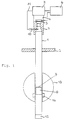
- a measuring tube 1 shows the principle of the measuring arrangement in a schematic representation.
- a measuring tube 1 is installed vertically by means of a flange 2 in a container, preferably in a tank system.
- an ultrasound transmitter / receiver consisting of an ultrasound transducer 3, a transducer housing 4, a temperature detection unit 5 and a driver unit 6.
- the driver unit 6 contains the means necessary to excite the ultrasound transducer 3, as well as those for processing the Transmit and receive signals of the same and means for operating the temperature detection unit 5 and processing its temperature signals.
- the driver unit 6 and the temperature detection unit 5 will not be discussed further below.
- the sound wave generated and emitted by the ultrasonic transducer 3 is coupled into the measuring tube 1 via an intermediate tube piece 7 and on the reflector surface 9 of the reflector 8 reflects, whereby part of the sound wave falls back on the ultrasonic transducer 3, which now works as a receiver.
- the returning and returning sound wave is recorded by means of a transit time measurement and evaluated in a known manner to determine a distance.
- At least one temperature sensor 10 is arranged in the intermediate pipe section 7 and is connected to the temperature detection unit 5 via the feed lines 11.
- the temperature sensor 10 can also be arranged at another point in the device, for example in the area of the measuring tube 1, in which a plurality of temperature sensors can also be arranged, which results in a better temperature overview.
- the measuring tube 1 is advantageously sealed at its lower end with an end piece 12 so that no filling material can get into the interior of the measuring tube.
- the reflector 8 is adjusted by means of a float 13, which is provided with a ring magnet 14, in such a way that the reflector surface 9 corresponds to the respective fill level of the filling material in the container.
- the reflector 8 consists essentially of plastic, and in particular its reflector surface 9 is advantageously made of a reverberant, flat plastic.
- the measuring tube 1 is made of plastic or metal, for example polyvinyl chloride (PVC) or steel. It is preferably made of stainless steel, which guarantees extensive corrosion resistance.
- Fig. 2 shows an embodiment of the converter housing 4 shown in section.
- An 'Environmental Ultrasonic Transducer' (Polaroid) was used as the ultrasonic transducer 3, which had an external dimensions of 10 mm x 38.5 mm. This was inserted into the converter housing 4 and clamped in by screwing the converter housing 4 to the intermediate tube piece 7.
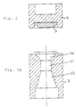
- 3A shows a first exemplary embodiment of the intermediate tube piece 7 in section. It is made from a piece of aluminum and, according to the invention, has the following three zones: an inlet funnel 20, a cylinder part 21 and an outlet funnel 22. The design of these three zones is essential for optimal sound propagation and transmission and must be coordinated with one another in terms of their construction dimensions.
- the diameter of the outlet funnel 22 on the measuring tube side is matched to the inside diameter of the measuring tube, so that there are no joints.
- the intermediate tube piece 7 is screwed to the measuring tube 1.
- the input funnel 20 has a diameter of 38.5 mm on the sensor side and tapers to 20 mm, with a cone length of approximately 13 mm resulting in a cone angle of approximately 36 degrees to the measuring tube axis.
- the cylinder part 21 has a diameter of 20 mm and a length of 20 mm.
- the outlet funnel 22 has a diameter of 20 mm on the sensor side and widens to 38.5 mm on the measuring tube side, a cone length of 33 mm resulting in a cone angle of approximately 16 degrees to the measuring tube axis.
- Fig. 3B shows a second embodiment of the intermediate tube piece 7 shown in section.
- the inlet funnel 20 has a diameter of 38.5 mm on the sensor side and tapers to 28 mm, a cone length of approximately 4.7 mm resulting in a cone angle of approximately 48 degrees to the measuring tube axis.
- the cylinder part 21 has a diameter of 28 mm and a length of 18.3 mm.
- the outlet funnel 22 has a diameter of 28 mm on the sensor side and widens to 38.5 mm on the measuring tube side, a cone length of 43 mm resulting in a cone angle of approximately 7 degrees to the measuring tube axis.
- Fig. 3C shows a third embodiment of the intermediate tube piece 7 shown in section.
- the input funnel 20 has a diameter of 38.5 mm on the sensor side and tapers to 18 mm, a cone length of approximately 21 mm resulting in a cone angle of approximately 26 degrees to the measuring tube axis.
- the cylinder part 21 has a diameter of 18 mm and a length of 20 mm.
- the outlet funnel 22 has a diameter of 18 mm on the sensor side and widens to 38.5 mm on the measuring tube side, a cone length of 25 mm resulting in a cone angle of approximately 22 degrees to the measuring tube axis.
- the specified resolution ⁇ S relates to the measured actual distance.
- the inventive distinction of the intermediate tube piece 7 ensures an optimal coupling of the ultrasonic transducer 3 to the Measuring tube 1 enables, as a result of which a complex and complex processing of the echo signals, in particular the elimination of interference signals, can essentially be dispensed with.
- the solution to the problem according to the invention is characterized by a high accuracy and high resolution over a large distance range, by a low power requirement in the driver unit, and by a low circuit complexity, since there is no need for complex processing of echo signals.
Landscapes
- Physics & Mathematics (AREA)
- General Physics & Mathematics (AREA)
- Engineering & Computer Science (AREA)
- Radar, Positioning & Navigation (AREA)
- Acoustics & Sound (AREA)
- Fluid Mechanics (AREA)
- Remote Sensing (AREA)
- Computer Networks & Wireless Communication (AREA)
- Multimedia (AREA)
- Electromagnetism (AREA)
- Thermal Sciences (AREA)
- Measurement Of Levels Of Liquids Or Fluent Solid Materials (AREA)
- Measurement Of Velocity Or Position Using Acoustic Or Ultrasonic Waves (AREA)
- Length Measuring Devices Characterised By Use Of Acoustic Means (AREA)
Applications Claiming Priority (3)
| Application Number | Priority Date | Filing Date | Title |
|---|---|---|---|
| CH1036/92A CH681914A5 (enExample) | 1992-03-31 | 1992-03-31 | |
| CH1036/92 | 1992-03-31 | ||
| PCT/CH1993/000084 WO1993020412A1 (de) | 1992-03-31 | 1993-03-25 | Vorrichtung zur messung einer distanz mittels ultraschall |
Publications (2)
| Publication Number | Publication Date |
|---|---|
| EP0587834A1 EP0587834A1 (de) | 1994-03-23 |
| EP0587834B1 true EP0587834B1 (de) | 1996-09-18 |
Family
ID=4200959
Family Applications (1)
| Application Number | Title | Priority Date | Filing Date |
|---|---|---|---|
| EP93905145A Expired - Lifetime EP0587834B1 (de) | 1992-03-31 | 1993-03-25 | Vorrichtung zur messung einer distanz mittels ultraschall |
Country Status (5)
| Country | Link |
|---|---|
| EP (1) | EP0587834B1 (enExample) |
| AT (1) | ATE143130T1 (enExample) |
| CH (1) | CH681914A5 (enExample) |
| DE (1) | DE59303843D1 (enExample) |
| WO (1) | WO1993020412A1 (enExample) |
Families Citing this family (4)
| Publication number | Priority date | Publication date | Assignee | Title |
|---|---|---|---|---|
| GB0105064D0 (en) * | 2001-03-01 | 2001-04-18 | Electronic Product Design Ltd | Apparatus and method of fluid level measurement |
| RU2193164C1 (ru) * | 2001-10-05 | 2002-11-20 | Балин Николай Иванович | Устройство для измерения уровня жидкости (варианты) |
| EP2087325A4 (en) * | 2006-11-28 | 2011-01-05 | Rubicon Res Pty Ltd | ULTRASONIC LEVEL DETECTION DEVICE WITH EVASED SECTION ENABLING REDUCED DISTORTION |
| DE102020205194A1 (de) * | 2020-04-23 | 2021-10-28 | Continental Automotive Gmbh | Sensorvorrichtung mit einem Ultraschallsensor |
Family Cites Families (4)
| Publication number | Priority date | Publication date | Assignee | Title |
|---|---|---|---|---|
| US1599914A (en) * | 1926-09-14 | Best available cop | ||
| DE2932243C2 (de) * | 1979-08-09 | 1982-04-22 | Eugen 2805 Stuhr Rapp | Füllstands- und Temperaturmeßgerät für Tankanlagen |
| DE3428132A1 (de) * | 1984-07-31 | 1985-06-13 | TC Technologie Consulting Institut für angewandte Forschung GmbH, 8000 München | Verfahren zur messung von fluessigkeitshoehen in behaeltern |
| US4732035A (en) * | 1987-02-06 | 1988-03-22 | Pandel Instruments, Inc. | Method and apparatus for storage tank leak detection having temperature compensation |
-
1992
- 1992-03-31 CH CH1036/92A patent/CH681914A5/de not_active IP Right Cessation
-
1993
- 1993-03-25 EP EP93905145A patent/EP0587834B1/de not_active Expired - Lifetime
- 1993-03-25 DE DE59303843T patent/DE59303843D1/de not_active Expired - Fee Related
- 1993-03-25 WO PCT/CH1993/000084 patent/WO1993020412A1/de not_active Ceased
- 1993-03-25 AT AT93905145T patent/ATE143130T1/de not_active IP Right Cessation
Also Published As
| Publication number | Publication date |
|---|---|
| ATE143130T1 (de) | 1996-10-15 |
| EP0587834A1 (de) | 1994-03-23 |
| CH681914A5 (enExample) | 1993-06-15 |
| WO1993020412A1 (de) | 1993-10-14 |
| DE59303843D1 (de) | 1996-10-24 |
Similar Documents
| Publication | Publication Date | Title |
|---|---|---|
| DE2713921C2 (de) | Vorrichtung zum Messen der radialen Abmessungen eines Rohres mittels Ultraschall | |
| DE4307635C2 (de) | Füllstandsmeßvorrichtung | |
| DE4336494C2 (de) | Vorrichtung zur Füllstandsmessung in Behältern | |
| DE102008029772A1 (de) | Verfahren und Messsystem zur Bestimmung und/oder Überwachung des Durchflusses eines Messmediums durch ein Messrohr | |
| EP3209976B1 (de) | Verfahren zur ultraschall-clamp-on-durchflussmessung und schaltungsanordnung zur steuerung einer ultraschall-clamp-on-durchflussmessung | |
| DE2837689A1 (de) | Ultraschallwandler | |
| EP0024589A2 (de) | Längen- und Temperaturmessgerät, insbesondere für Tankanlagen od. dgl. | |
| DE4306193B4 (de) | Füllstandssensor | |
| EP3343185B1 (de) | Ultraschalldurchflussmessgerät und verfahren zur messung des durchflusses | |
| EP0587834B1 (de) | Vorrichtung zur messung einer distanz mittels ultraschall | |
| EP0773431A2 (de) | Ultraschalldurchflussmesser für flüssige oder gasförmige Medien | |
| DE3013482C2 (de) | Ultraschallkopf | |
| EP3612802A1 (de) | Ultraschall-durchflussmesseinrichtung | |
| DE2820120C2 (enExample) | ||
| DE3431741A1 (de) | Vorrichtung zur messung des fuellstandes von fluessigkeiten | |
| DE102004031274A1 (de) | Verfahren zur Kalibrierung von Ultraschall-Clamp-on-Durchflussmessgeräten und Ultraschall-Clamp-on-Durchflussmessgerät nach dem Laufzeitdifferenzverfahren | |
| EP1762841A1 (de) | Verfahren und Einrichtung zur Ultraschallprüfung eines Werkstückes mit einer unebenen Oberfläche | |
| DE2622505A1 (de) | Messgeraet zur messung des walzenspaltes in dickengeregelten walzgeruesten | |
| DE3003153A1 (de) | Ultraschall-multi-sensor | |
| WO2019137710A1 (de) | Ultraschallreflektor, ultraschallsensor und fluidtank mit einem ultraschallsensor | |
| DE3210591A1 (de) | Anordnung fuer eine kontinuierliche blasengehaltsmessung in hydraulikfluessigkeiten | |
| DE69402696T2 (de) | Vorrichtung zum aufspüren im boden eingebetteter objekte | |
| DE102006056735A1 (de) | Messverfahren zur Bestimmung der Wanddicke eines extrudierten Kunststoffprofils | |
| DE1648997B2 (de) | Verfahren und vorrichtung zum nachweis von fluessigkeits-fluid-grenzflaechen | |
| DE2911704C3 (de) | Geschwindigkeitssensor zur Bestimmung der Strömungsgeschwindigkeit von Strömungsmedien nach der Schallmitführungsmethode |
Legal Events
| Date | Code | Title | Description |
|---|---|---|---|
| PUAI | Public reference made under article 153(3) epc to a published international application that has entered the european phase |
Free format text: ORIGINAL CODE: 0009012 |
|
| 17P | Request for examination filed |
Effective date: 19931224 |
|
| AK | Designated contracting states |
Kind code of ref document: A1 Designated state(s): AT BE DE DK ES FR GB GR IE IT NL PT SE |
|
| 17Q | First examination report despatched |
Effective date: 19940701 |
|
| GRAH | Despatch of communication of intention to grant a patent |
Free format text: ORIGINAL CODE: EPIDOS IGRA |
|
| GRAH | Despatch of communication of intention to grant a patent |
Free format text: ORIGINAL CODE: EPIDOS IGRA |
|
| GRAA | (expected) grant |
Free format text: ORIGINAL CODE: 0009210 |
|
| AK | Designated contracting states |
Kind code of ref document: B1 Designated state(s): AT BE DE DK ES FR GB GR IE IT NL PT SE |
|
| PG25 | Lapsed in a contracting state [announced via postgrant information from national office to epo] |
Ref country code: NL Free format text: LAPSE BECAUSE OF FAILURE TO SUBMIT A TRANSLATION OF THE DESCRIPTION OR TO PAY THE FEE WITHIN THE PRESCRIBED TIME-LIMIT Effective date: 19960918 Ref country code: IT Free format text: LAPSE BECAUSE OF FAILURE TO SUBMIT A TRANSLATION OF THE DESCRIPTION OR TO PAY THE FEE WITHIN THE PRESCRIBED TIME-LIMIT;WARNING: LAPSES OF ITALIAN PATENTS WITH EFFECTIVE DATE BEFORE 2007 MAY HAVE OCCURRED AT ANY TIME BEFORE 2007. THE CORRECT EFFECTIVE DATE MAY BE DIFFERENT FROM THE ONE RECORDED. Effective date: 19960918 Ref country code: GR Free format text: LAPSE BECAUSE OF FAILURE TO SUBMIT A TRANSLATION OF THE DESCRIPTION OR TO PAY THE FEE WITHIN THE PRESCRIBED TIME-LIMIT Effective date: 19960918 Ref country code: GB Effective date: 19960918 Ref country code: FR Effective date: 19960918 Ref country code: ES Free format text: THE PATENT HAS BEEN ANNULLED BY A DECISION OF A NATIONAL AUTHORITY Effective date: 19960918 Ref country code: DK Effective date: 19960918 |
|
| REF | Corresponds to: |
Ref document number: 143130 Country of ref document: AT Date of ref document: 19961015 Kind code of ref document: T |
|
| REF | Corresponds to: |
Ref document number: 59303843 Country of ref document: DE Date of ref document: 19961024 |
|
| REG | Reference to a national code |
Ref country code: IE Ref legal event code: FG4D Free format text: 69908 |
|
| PG25 | Lapsed in a contracting state [announced via postgrant information from national office to epo] |
Ref country code: SE Effective date: 19961218 Ref country code: PT Effective date: 19961218 |
|
| EN | Fr: translation not filed | ||
| NLV1 | Nl: lapsed or annulled due to failure to fulfill the requirements of art. 29p and 29m of the patents act | ||
| GBV | Gb: ep patent (uk) treated as always having been void in accordance with gb section 77(7)/1977 [no translation filed] |
Effective date: 19960918 |
|
| PG25 | Lapsed in a contracting state [announced via postgrant information from national office to epo] |
Ref country code: BE Effective date: 19970331 |
|
| PG25 | Lapsed in a contracting state [announced via postgrant information from national office to epo] |
Ref country code: IE Free format text: LAPSE BECAUSE OF NON-PAYMENT OF DUE FEES Effective date: 19970416 |
|
| REG | Reference to a national code |
Ref country code: IE Ref legal event code: FD4D Ref document number: 69908 Country of ref document: IE |
|
| PLBE | No opposition filed within time limit |
Free format text: ORIGINAL CODE: 0009261 |
|
| STAA | Information on the status of an ep patent application or granted ep patent |
Free format text: STATUS: NO OPPOSITION FILED WITHIN TIME LIMIT |
|
| 26N | No opposition filed | ||
| PGFP | Annual fee paid to national office [announced via postgrant information from national office to epo] |
Ref country code: DE Payment date: 19990319 Year of fee payment: 7 Ref country code: AT Payment date: 19990319 Year of fee payment: 7 |
|
| PG25 | Lapsed in a contracting state [announced via postgrant information from national office to epo] |
Ref country code: AT Free format text: LAPSE BECAUSE OF NON-PAYMENT OF DUE FEES Effective date: 20000325 |
|
| PG25 | Lapsed in a contracting state [announced via postgrant information from national office to epo] |
Ref country code: DE Free format text: LAPSE BECAUSE OF NON-PAYMENT OF DUE FEES Effective date: 20010103 |