EP0587199A2 - A nonaqueous electrochemical cell and a method of manufacturing the same - Google Patents
A nonaqueous electrochemical cell and a method of manufacturing the same Download PDFInfo
- Publication number
- EP0587199A2 EP0587199A2 EP93118487A EP93118487A EP0587199A2 EP 0587199 A2 EP0587199 A2 EP 0587199A2 EP 93118487 A EP93118487 A EP 93118487A EP 93118487 A EP93118487 A EP 93118487A EP 0587199 A2 EP0587199 A2 EP 0587199A2
- Authority
- EP
- European Patent Office
- Prior art keywords
- cathode
- electrochemical cell
- separator
- pet
- electrolyte
- Prior art date
- Legal status (The legal status is an assumption and is not a legal conclusion. Google has not performed a legal analysis and makes no representation as to the accuracy of the status listed.)
- Granted
Links
Images
Classifications
-
- H—ELECTRICITY
- H01—ELECTRIC ELEMENTS
- H01M—PROCESSES OR MEANS, e.g. BATTERIES, FOR THE DIRECT CONVERSION OF CHEMICAL ENERGY INTO ELECTRICAL ENERGY
- H01M4/00—Electrodes
- H01M4/02—Electrodes composed of, or comprising, active material
- H01M4/06—Electrodes for primary cells
- H01M4/08—Processes of manufacture
- H01M4/12—Processes of manufacture of consumable metal or alloy electrodes
-
- H—ELECTRICITY
- H01—ELECTRIC ELEMENTS
- H01M—PROCESSES OR MEANS, e.g. BATTERIES, FOR THE DIRECT CONVERSION OF CHEMICAL ENERGY INTO ELECTRICAL ENERGY
- H01M50/00—Constructional details or processes of manufacture of the non-active parts of electrochemical cells other than fuel cells, e.g. hybrid cells
- H01M50/40—Separators; Membranes; Diaphragms; Spacing elements inside cells
- H01M50/409—Separators, membranes or diaphragms characterised by the material
- H01M50/431—Inorganic material
- H01M50/434—Ceramics
- H01M50/437—Glass
-
- H—ELECTRICITY
- H01—ELECTRIC ELEMENTS
- H01M—PROCESSES OR MEANS, e.g. BATTERIES, FOR THE DIRECT CONVERSION OF CHEMICAL ENERGY INTO ELECTRICAL ENERGY
- H01M4/00—Electrodes
- H01M4/02—Electrodes composed of, or comprising, active material
- H01M4/64—Carriers or collectors
- H01M4/66—Selection of materials
- H01M4/663—Selection of materials containing carbon or carbonaceous materials as conductive part, e.g. graphite, carbon fibres
-
- H—ELECTRICITY
- H01—ELECTRIC ELEMENTS
- H01M—PROCESSES OR MEANS, e.g. BATTERIES, FOR THE DIRECT CONVERSION OF CHEMICAL ENERGY INTO ELECTRICAL ENERGY
- H01M50/00—Constructional details or processes of manufacture of the non-active parts of electrochemical cells other than fuel cells, e.g. hybrid cells
- H01M50/40—Separators; Membranes; Diaphragms; Spacing elements inside cells
- H01M50/409—Separators, membranes or diaphragms characterised by the material
- H01M50/44—Fibrous material
-
- H—ELECTRICITY
- H01—ELECTRIC ELEMENTS
- H01M—PROCESSES OR MEANS, e.g. BATTERIES, FOR THE DIRECT CONVERSION OF CHEMICAL ENERGY INTO ELECTRICAL ENERGY
- H01M6/00—Primary cells; Manufacture thereof
- H01M6/14—Cells with non-aqueous electrolyte
-
- H—ELECTRICITY
- H01—ELECTRIC ELEMENTS
- H01M—PROCESSES OR MEANS, e.g. BATTERIES, FOR THE DIRECT CONVERSION OF CHEMICAL ENERGY INTO ELECTRICAL ENERGY
- H01M2300/00—Electrolytes
- H01M2300/0017—Non-aqueous electrolytes
-
- H—ELECTRICITY
- H01—ELECTRIC ELEMENTS
- H01M—PROCESSES OR MEANS, e.g. BATTERIES, FOR THE DIRECT CONVERSION OF CHEMICAL ENERGY INTO ELECTRICAL ENERGY
- H01M2300/00—Electrolytes
- H01M2300/0017—Non-aqueous electrolytes
- H01M2300/0025—Organic electrolyte
-
- Y—GENERAL TAGGING OF NEW TECHNOLOGICAL DEVELOPMENTS; GENERAL TAGGING OF CROSS-SECTIONAL TECHNOLOGIES SPANNING OVER SEVERAL SECTIONS OF THE IPC; TECHNICAL SUBJECTS COVERED BY FORMER USPC CROSS-REFERENCE ART COLLECTIONS [XRACs] AND DIGESTS
- Y02—TECHNOLOGIES OR APPLICATIONS FOR MITIGATION OR ADAPTATION AGAINST CLIMATE CHANGE
- Y02E—REDUCTION OF GREENHOUSE GAS [GHG] EMISSIONS, RELATED TO ENERGY GENERATION, TRANSMISSION OR DISTRIBUTION
- Y02E60/00—Enabling technologies; Technologies with a potential or indirect contribution to GHG emissions mitigation
- Y02E60/10—Energy storage using batteries
-
- Y—GENERAL TAGGING OF NEW TECHNOLOGICAL DEVELOPMENTS; GENERAL TAGGING OF CROSS-SECTIONAL TECHNOLOGIES SPANNING OVER SEVERAL SECTIONS OF THE IPC; TECHNICAL SUBJECTS COVERED BY FORMER USPC CROSS-REFERENCE ART COLLECTIONS [XRACs] AND DIGESTS
- Y02—TECHNOLOGIES OR APPLICATIONS FOR MITIGATION OR ADAPTATION AGAINST CLIMATE CHANGE
- Y02P—CLIMATE CHANGE MITIGATION TECHNOLOGIES IN THE PRODUCTION OR PROCESSING OF GOODS
- Y02P70/00—Climate change mitigation technologies in the production process for final industrial or consumer products
- Y02P70/50—Manufacturing or production processes characterised by the final manufactured product
Definitions
- the present invention relates to a nonaqueous electrochemical cell comprising an alkali metal, such as metallic lithium, as an anode active substance, an oxyhalide or the like which is liquid at ambient temperature as a cathodic active substance-electrolyte solvent, and a porous carbonaceous element as a cathode collector.
- an alkali metal such as metallic lithium
- an oxyhalide or the like which is liquid at ambient temperature as a cathodic active substance-electrolyte solvent
- a porous carbonaceous element as a cathode collector.
- a nonaqueous electrochemical cell comprising an alkali metal, such as metallic lithium, as an anode active substance, an oxyhalide or the like which is liquid at ambient temperature as a cathodic active substance-electrolyte solvent, and a porous carbonaceous element as a cathode collector, the anode active substance and the cathode active substance are directly contacted with each other so that a discharge reaction product is formed on their interface by self-discharge.
- an alkali metal such as metallic lithium
- This discharge reaction product forms a progressively growing film on the surface of the anode active substance, such as metallic lithium, but as this film increases in thickness, it functions as a protective or passivating film preventing direct contact of the cathode active substance and anode active substance to prevent a loss of capacity due to self-discharge of the cell and any further film growth is also arrested.
- a film formed on the surface of the anode acts as resistance component in discharge of the cell to cause a large voltage drop in the initial stage of large current discharge. This marked voltage drop occurring in the initial stage of discharge is known as voltage delay.
- additives to the liquid cathode-electrolyte system.
- high molecular materials such as polyvinyl chloride (United States Patent 3,993,501), alkyl 2-cyanoacrylates (USP 4,402,995) and chlorinated polypropylene (JP-A 60-249253; JP-A means Japanese Patent Laid-Open Application) and inorganic materials such as Li2O (USP 4,228,229), Li2B10Cl10 (USP 4,071,664) and SeO2 (JP-A 62-43069).
- the porous carbonaceous cathode collector which functions as the site of discharge reaction and the separator isolating the anode from the cathode must respectively have a sufficient porosity to assure a stable retention of the liquid cathode-electrolyte.
- its porosity is preferably 82% (USP 4,228,229) or 80 to 90% (JP-A 59-171467).
- the preferred porosity is said to be 50 to 75% or it may be a glass fibre separator containing 91 to 94 weight % of glass fibre (USP 4,421,834).
- the use of an acrylic resin has also been proposed to implement a separator of improved mechanical strength (JP-A 61-16465).
- European Patent Application EP-A-0219190 discloses a polymeric component for use as a separator in an electrochemical device in which the anode comprises lithium, the component comprising a thermoplastic polymer, a tertiary plasticiser and a filler that comprises a lithium compound which is substantially insoluble in both the polymer and the plasticiser.
- Useful polymers listed in this disclosure include polyethylene terephthalate.
- the technologies of incorporating various additives in the liquid cathode-electrolyte are disadvantageous in that some involve complicated assembling procedures, others tend to detract from environmental safety and still others entail increased production costs.
- the cells so fabricated may normally function fairly well but at high ambient temperatures or in an early stage of large-current discharge, they show a voltage drop, known as voltage delay, so that these cells are not sufficiently useful for practical purposes.
- the present invention comprises employing polyethylene terephthalate as an essential additive for suppressing the voltage delay in a nonaqueous electrochemical cell.
- PET polyethylene terephthalate
- EP-A-90300611.2 European Patent Application EP-A-90300611.2
- the present invention concerns the addition of polyethylene terephthalate to the porous carbonaceous cathode collector or the glass fibre separator of such electrochemical cells.
- PET is an additive to, rather than as a main component of the separator, or as an additive to the carbonaceous cathode-collector the previously undisclosed and advantageous lowering of voltage delay can be realised.
- the mechanical strength of the collector or the separator can be enhanced and the internal short-circuit of the cell due to breakage of the separator or chipping of the porous carbonaceous cathode collector in the fabrication of the cell can be prevented.
- a nonaqueous electrochemical cell comprising an alkali metal anode, a glass fibre separator, a liquid cathode-electrolyte and a porous carbonaceous cathode collector, characterised in that said glass fibre separator or said cathode collector contain polyethylene terephthalate as an additive.
- separatator means not only a cylindrical body as such but also the member at the top or bottom thereof which serves to hold the porous carbonaceous cathode collector in isolation from the lithium anode and the cell housing.
- the inventors provided a nonaqueous electrochemical cell showing a minimum of voltage delay even at a high ambient temperature or an prolonged storage.
- PET Polyethylene terephthalate
- PVC polyvinyl chloride
- the effect of PET is different from that of PVC.
- a possible explanation of the effect of PET is the effect 1) proposed by Boyd, that is the covering of the Li surface.
- the effect of PVC may be the effect 2), that is deposition on LiCl crystals which inhibits the growth of LiCl crystals.
- both PET and PVC are dissolved in an oxyhalide such as thionyl chloride as colloidal polymers in the cell but when their concentrations are high, they adhere not only to the Li surface but to the surfaces of the porous carbonaceous cathode collector and separator to function as resistance factors contributing to a voltage drop in discharge. Therefore, the upper limit of addition is preferably 3.0 weight % for PET and 0.5 weight % for PVC.
- the preferred concentration range of PET is 0.01 to 3.0 weight % and that of PVC is 0.01 to 0.5 weight %. If the concentration of either additive is less than 0.01 weight %, the desired effect cannot be fully accomplished.
- the preferred range of addition per unit area of the separator is 1 to 30 g/m2.
- the preferred range is 1 to 10 weight % based on the total weight of the cathode.
- the separator and porous carbonaceous cathode collector since both are inherently high in porosity and low in mechanical strength, breakage or chipping tends to occur in cell assembling to increase the incidence of rejects.
- the incorporation of PET in the separator or the porous carbonaceous cathode collector serves to increase their mechanical strength to reduce the incidence of rejects in the fabrication of cells and contributes to a marked improvement in filling uniformity.
- Which of the separator and the porous carbonaceous cathode collector is to be chosen for incorporation of PET depends on their relative mechanical strength as well as the manufacturing method adopted but in view of its geometrical proximity to the anode surface, the separator is the better choice.
- the incorporation of PET in the porous carbonaceous cathode collector also serves to increase the collector porosity due to the pores left behind after dissolution of PET to thereby improve the discharge efficiency.
- the incorporation of PET in the separator or the porous carbonaceous cathode collector contributes to a reduced incidence of rejects in cell assembling but requires additional steps for adding PET, washing and drying, thus complicating the manufacturing process and, hence, resulting in an industrial disadvantage.
- PET as an exclusive binder leads to a marked reduction of strength after release of PET within the cell so that the normal discharge function cannot be obtained. Therefore, it is sometimes advisable to use PET in combination with a different binder in the fabrication of the porous carbonaceous cathode collector.
- the acrylic resin which is the common binder for the glass fiber separator is resistant to the electrolyte but is not much effective in improving the mechanical strength of the separator.
- a separator satisfactory in cell characteristics and manufacturing technology can be provided by using PET and an acrylic resin in the optimum ratio of 1:0.5 to 1.5.
- the use of PET in combination with polytetrafluoroethylene (PTFE), which is one of the common binders results in improved mechanical strength of the cathode and improved porosity due to formation of effective pores in the collector.
- PTFE polytetrafluoroethylene
- the release of PET within the cell causes a decrease in the mechanical strength of the porous carbonaceous cathode collector. Therefore, the use of PET in a large proportion may adversely affect the cell characteristic. Therefore, the optimum proportion of PET is 1 to 10 weight % of the total cathode weight.
- PTFE polytetrafluoroethylene
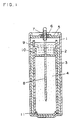
- Fig. 1 is a cross-section view showing an embodiment of the nonaqueous electrochemical cell according to the invention.
- Examples 1 to 10 of which Examples 3 to 10 are embodiments of the invention, are described below, taking a thionyl chloride-lithium cell as an example and referring to the accompanying drawing. Examples 1 and 2 are included in order to demonstrate the advantage of the embodiments of the invention over Examples 1 and 2, which do not contain PET in either the separator or the cathode-collector.
- FIG. 1 which is a cross-section view showing a bobbin-shaped thionyl chloride-lithium electrochemical cell
- the reference numeral 1 represents a stainless steel cell housing which serves as an anode terminal
- 2 represents a cylindrical metallic lithium element measuring 0.85 mm thick, 37 mm long and 37 mm wide and fitted against the inner surface of said cell housing for functioning as an anode.
- the reference numeral 3 represents a glass fiber separator containing 15 weight % of an arylic resin binder and measuring 0.2 mm in thickness
- 4 represents a porous carbonaceous collector extrusion-molded from a well-kneaded mixture of 78 weight % acetylene black, 9 weight % artificial graphite, 13 weight % PTFE binder with water-ethanol and dried in vacuo at 150°C for 12 hours.
- the cathode is a cylinder, 10 mm in diameter and 30 mm high, with a porosity of 82%.
- Represented by the numeral 5 is a stainless steel cell cover, the peripheral edge thereof being laser-welded to the open end of said cell housing 1.
- a hollow cathode terminal 7 Disposed in the center of said cell cover 5 is a hollow cathode terminal 7 insulated by glass wool 6.
- This cathode terminal 7 is laser-melded, at its top, to a nail-shaped cathode collector 8.
- a liquid cathode-electrolyte is prepared by dissolving lithium tetrachloroaluminate (LiAlCl4) in thionyl chloride at a final electrolyte concentration of 1.2 moles/liter and adding polyethylene terephthalate (PET) at a concentration of 0.5 weight %.
- PET polyethylene terephthalate
- the volume of the cathode active substance-electrolyte solution is 4.0 ml.
- the reference numerals 10 and 11 represent a top and a bottom separator, each made of the same glass fiber material as the separator 3.
- An electrochemical cell was fabricated in the same manner as Example 1 except that a thionyl chloride solution containing 1.2 moles/l of LiAlCl4, 0.5 weight % of PET and 0.1 weight % of polyvinyl chloride (PVC) was used as the liquid cathode-electrolyte.
- a thionyl chloride solution containing 1.2 moles/l of LiAlCl4, 0.5 weight % of PET and 0.1 weight % of polyvinyl chloride (PVC) was used as the liquid cathode-electrolyte.
- Example 2 In 100 ml of o-chlorophenol was dissolved 5 g of PET by heating at 60-70°C. The same glass fiber separator as the one used in Example 1 was impregnated with the above PET solution for one hour and, then, washed thoroughly with ethanol to remove the o-chlorophenol. The separator was then dried in vacuo at 110°C to give a finished glass fiber separator with a PET content of about 12 g/m2. Using this separator, an electrochemical cell was fabricated in otherwise the same manner as Example 1.
- Example 3 Except that a thionyl chloride solution of 1.2 moles/l of LiAlCl4 supplemented with 0.1 weight % of PVC was used as a cathode-electrolyte solution, the procedure of Example 3 was repeated to fabricate an electrochemical cell.
- Example 1 Except that a glass fibre separator impregnated with 15 weight % of PET and 15 weight % of an acrylic resin as binders was used, a finished glass fibre separator was prepared. Using this separator, an electrochemical cell was fabricated in otherwise the same manner as Example 1.
- Example 5 Using the separator of Example 5 and the thionyl chloride electrolyte solution of Example 4, an electrochemical cell was fabricated in the same manner as Example 1.
- Example 2 In 100 ml of dimethylformamide was dissolved 6g of PET by heating at 50-60°C. The same molded porous carbonaceous cathode collector as used in Example 1 was impregnated with the resulting PET solution and washed thoroughly with water and ethanol to remove the solvent dimethylformamide. The collector was then dried in vacuo to give a porous carbonaceous cathode collector with a PET content of about 6 weight %. Except that the above carbonaceous collector was employed, the same procedure of Example 1 was followed to fabricate an electrochemical cell.
- Example 1 Using the carbonaceous collector of Example 7 and the thionyl chloride electrolyte solution of Example 4, the procedure of Example 1 was repeated to fabricate an electrochemical cell.
- a well-blended mixture of finely divided PET fiber, acetylene black and artificial graphite was kneaded with an aqueous dispersion of polytetrafluoroethylene (PTFE), ethanol and water and the resulting composition was extrusion-molded.
- the composition consisted of 76 weight % acetylene black, 8 weight % artificial graphite, 13 weight % PTFE and 3 weight % PET.
- the molded collector was then dried in vacuo at 150°C for 12 hours to give a finished porous carbonaceous cathode collector measuring 10 mm in diameter and 30 mm high. Except that this cathode collector was used, the procedure of Example 1 was repeated to fabricate an electrochemical cell.
- Example 9 Using the porous carbonaceous cathode collector of Example 9 and the thionyl chloride electrolyte solution of Example 4, an electrochemical cell was fabricated in otherwise the same manner as Example 1.
- Example 4 Using the thionyl chloride electrolyte solution containing 0.1 weight % of PVC prepared in the same manner as Example 4, an electrochemical cell was fabricated in the same manner as Example 1.
- the internal resistance of the cell was measured at 1 KHz for 10 wholesome units of the cells of Examples 1 to 10 and Comparative Example 1 to 2, excluding the cell of Comparative Example 3 which showed a very high incidence of rejects, one day and one week after fabrication.
- the minimum and maximum values are presented in Table 2. These units of the cells were also stored at 60°C for 20 days and the internal resistance of the cell was similarly measured. The results are also shown in Table 2. Furthermore, the cells showing a median internal resistance after the 20-day storage at 60°C were subjected to constant current discharge at 40 mA (20°C) and the minimum voltage in the initial stage of discharge (up to 50 msec) was measured. The results are also presented in Table 2.
- the voltage delay in the cells was evaluated by subjecting the cells after the 20-day storage at 60°C to a constant current discharge of 40 mA and measuring the lowest voltage in the initial stage of discharge (up to 50 msec).
- the data showed that all the cells of Examples 1 to 10 of the invention are superior to the cell of Comparative Example 2.
- the combined use of PET and PVC is more effective than the use of PET alone (for example, Example 1 vs. Examples 2, 3 and 4).
- PET fiber was incorporated as a binder in the porous carbonaceous cathode collector, the effects were less than those in the other Examples and the plausible reason for this difference is that PET in these porous carbonaceous cathode collectors are harder to be released into the electrolyte.
- PET is not limited to the one used in the examples but the use of other oxyhalides such as trifluoroacetic acid, concentrated sulfuric acid, thionyl chloride, etc. as solvents and the use of a thin film of PET as bonded by fusion also fall within the scope of the invention.
- other oxyhalides such as trifluoroacetic acid, concentrated sulfuric acid, thionyl chloride, etc. as solvents and the use of a thin film of PET as bonded by fusion also fall within the scope of the invention.
- PET was incorporated selectively in the separator or the porous carbonaceous cathode collector, it is possible to incorporate PET in both of these members.
- the effects of the invention can also be implemented by using the PET-containing separator in combination with any other separator or incorporating PET only in the top separator and/or the bottom separator.
Landscapes
- Chemical & Material Sciences (AREA)
- Chemical Kinetics & Catalysis (AREA)
- Electrochemistry (AREA)
- General Chemical & Material Sciences (AREA)
- Engineering & Computer Science (AREA)
- Ceramic Engineering (AREA)
- Inorganic Chemistry (AREA)
- Manufacturing & Machinery (AREA)
- Materials Engineering (AREA)
- Primary Cells (AREA)
- Battery Electrode And Active Subsutance (AREA)
Abstract
Description
- The present invention relates to a nonaqueous electrochemical cell comprising an alkali metal, such as metallic lithium, as an anode active substance, an oxyhalide or the like which is liquid at ambient temperature as a cathodic active substance-electrolyte solvent, and a porous carbonaceous element as a cathode collector.
- In a nonaqueous electrochemical cell comprising an alkali metal, such as metallic lithium, as an anode active substance, an oxyhalide or the like which is liquid at ambient temperature as a cathodic active substance-electrolyte solvent, and a porous carbonaceous element as a cathode collector, the anode active substance and the cathode active substance are directly contacted with each other so that a discharge reaction product is formed on their interface by self-discharge. This discharge reaction product forms a progressively growing film on the surface of the anode active substance, such as metallic lithium, but as this film increases in thickness, it functions as a protective or passivating film preventing direct contact of the cathode active substance and anode active substance to prevent a loss of capacity due to self-discharge of the cell and any further film growth is also arrested. However, such a film formed on the surface of the anode acts as resistance component in discharge of the cell to cause a large voltage drop in the initial stage of large current discharge. This marked voltage drop occurring in the initial stage of discharge is known as voltage delay.
- To diminish this voltage delay in a cell using a liquid cathodic active substance such as an oxyhalide, it has been proposed to add a variety of additives to the liquid cathode-electrolyte system. Among these additives are high molecular materials such as polyvinyl chloride (United States Patent 3,993,501), alkyl 2-cyanoacrylates (USP 4,402,995) and chlorinated polypropylene (JP-A 60-249253; JP-A means Japanese Patent Laid-Open Application) and inorganic materials such as Li₂O (USP 4,228,229), Li₂B₁₀Cl₁₀ (USP 4,071,664) and SeO₂ (JP-A 62-43069). With regard to methods of incorporation of such additives, addition to the active substance-electrolyte solution (USP 4,277,545), formation of a vinyl polymer film on the anode (USP 3,993,501), formation of a vinyl polymer film on the separator (USP 4,278,741) and formation of a vinyl polymer film on the porous carbonaceous cathode collector (USP 4,560,632) have been proposed and claimed to be practically successful.
- In order to assure an effective utilization of the liquid cathode-electrolyte, the porous carbonaceous cathode collector which functions as the site of discharge reaction and the separator isolating the anode from the cathode must respectively have a sufficient porosity to assure a stable retention of the liquid cathode-electrolyte. Taking the carbonaceous cathode collector as an example, its porosity is preferably 82% (USP 4,228,229) or 80 to 90% (JP-A 59-171467). With regard to the separator, the preferred porosity is said to be 50 to 75% or it may be a glass fibre separator containing 91 to 94 weight % of glass fibre (USP 4,421,834). The use of an acrylic resin has also been proposed to implement a separator of improved mechanical strength (JP-A 61-16465).
- European Patent Application EP-A-0219190 discloses a polymeric component for use as a separator in an electrochemical device in which the anode comprises lithium, the component comprising a thermoplastic polymer, a tertiary plasticiser and a filler that comprises a lithium compound which is substantially insoluble in both the polymer and the plasticiser. Useful polymers listed in this disclosure include polyethylene terephthalate. The technologies of incorporating various additives in the liquid cathode-electrolyte are disadvantageous in that some involve complicated assembling procedures, others tend to detract from environmental safety and still others entail increased production costs. Furthermore the cells so fabricated may normally function fairly well but at high ambient temperatures or in an early stage of large-current discharge, they show a voltage drop, known as voltage delay, so that these cells are not sufficiently useful for practical purposes.
- Furthermore, in order to assure an effective utilization of the liquid cathode-electrolyte, it is essential to use a highly porous carbonaceous cathode collector and a glass fiber separator rich in porosity and glass component. This means that both the cathode collector and separator are not sturdy enough, thus causing troubles in the fabrication of cells.
- It is an object of the present invention to provide a nonaqueous electrochemical cell with a minimum of voltage delay even at a high ambient temperature or on prolonged storage.
- It is a further object of the invention to provide a nonaqueous electrochemical cell which overcomes the disadvantages, in terms of mechanical strength, of the highly porous carbonaceous cathode collector and glass fiber separator necessary for effective utilization of a liquid cathode-electrolyte and which can be fabricated with high reproducibility and at low cost.
- The above-mentioned objects are accomplished by the present invention, which comprises employing polyethylene terephthalate as an essential additive for suppressing the voltage delay in a nonaqueous electrochemical cell.
- The addition of polyethylene terephthalate (PET) can be accomplished by addition to the liquid cathode-electrolyte. This is the subject of European Patent Application EP-A-90300611.2, of which the present application is a divisional application. The present invention concerns the addition of polyethylene terephthalate to the porous carbonaceous cathode collector or the glass fibre separator of such electrochemical cells. By virtue of the use of PET as an additive to, rather than as a main component of the separator, or as an additive to the carbonaceous cathode-collector the previously undisclosed and advantageous lowering of voltage delay can be realised. In addition to this advantage, the mechanical strength of the collector or the separator can be enhanced and the internal short-circuit of the cell due to breakage of the separator or chipping of the porous carbonaceous cathode collector in the fabrication of the cell can be prevented.
- According to the present invention, there is provided a nonaqueous electrochemical cell comprising an alkali metal anode, a glass fibre separator, a liquid cathode-electrolyte and a porous carbonaceous cathode collector, characterised in that said glass fibre separator or said cathode collector contain polyethylene terephthalate as an additive.
- The term "separator" as used herein means not only a cylindrical body as such but also the member at the top or bottom thereof which serves to hold the porous carbonaceous cathode collector in isolation from the lithium anode and the cell housing.
- By these innovations briefly mentioned above, the inventors provided a nonaqueous electrochemical cell showing a minimum of voltage delay even at a high ambient temperature or an prolonged storage.
- Furthermore, even with a sufficient porosity to assure an effective utilization of the liquid cathode-electrolyte, it is by now possible to provide a glass fiber separator and a porous carbonaceous collector both having sufficient mechanical strength.
- One theory about the rationale of addition of a high polymer additive for inhibiting the voltage delay in association with the use of a liquid cathode active substance such as an oxyhalide is shown in the paper of J.W. Boyd which discusses on the effect of polyvinyl chloride on the film growth and voltage delay in the thionyl chloride (SOCl₂) electrolyte system (J. Electrochem. Soc. 134, 18-24, 1987). According to the author, the beneficial effect of polyvinyl chloride on passivation on the lithium surface in 1.5 moles/ℓ LiAlCl₄-SOCl₂ solution is said to result from the following two effects of PVC.
- 1) As the lithium surface is coated with a vinyl polymer, the coating serves as a spacer between lithium (Li) and lithium chloride (LiCl) films so that the LiCl film becomes easier to be broken as the current flows.
- 2) As the vinyl polymer is deposited on LiCl crystals, normal crystal growth is hindered to form large pores and tunnels, thus facilitating ion conduction.
- Polyethylene terephthalate (PET) is a polymer of the formula (1)

and, as such, differs from polyvinyl chloride (PVC) of the formula (2)
However, it is probable that the lithium surface is coated with PET in a similar manner to what happens with PVC. The mechanism of deposition or binding of PVC on the Li surface remains to be elucidated but if the contribution of the C-Cl bond is postulated, the presence of carbonyl (〉C=O) and carboxyl residue (COO) in PET, too, suggests the deposition or binding of PET on the Li surface by the same mechanism. For example, assuming that the electronegativity of a substituent is a factor, it is 0.21 in the case of (C-Cl) and 0.42, or about two-fold higher, for (C=O). (Minoru Imoto: Organic Electron Theory 1, Kyoritsu Zensho 55, Kyoritsu Shuppan, Japan, p29-32 (1955)). - However, the fact that the concomitant presence of PET and PVC results in a marked inhibition of voltage delay suggests that the effect of PET is different from that of PVC. A possible explanation of the effect of PET is the effect 1) proposed by Boyd, that is the covering of the Li surface. On the other hand, the effect of PVC may be the effect 2), that is deposition on LiCl crystals which inhibits the growth of LiCl crystals.
- Furthermore, both PET and PVC are dissolved in an oxyhalide such as thionyl chloride as colloidal polymers in the cell but when their concentrations are high, they adhere not only to the Li surface but to the surfaces of the porous carbonaceous cathode collector and separator to function as resistance factors contributing to a voltage drop in discharge. Therefore, the upper limit of addition is preferably 3.0 weight % for PET and 0.5 weight % for PVC.
- Therefore, when they are dissolved in the liquid cathode-electrolyte, the preferred concentration range of PET is 0.01 to 3.0 weight % and that of PVC is 0.01 to 0.5 weight %. If the concentration of either additive is less than 0.01 weight %, the desired effect cannot be fully accomplished.
- When PET is incorporated in the glass fiber separator, the preferred range of addition per unit area of the separator is 1 to 30 g/m². When the additive is to be incorporated in the porous carbonaceous cathode collector, the preferred range is 1 to 10 weight % based on the total weight of the cathode. When PET is incorporated in the separator and/or the porous carbonaceous cathode collector, the PET first dissolves within the cell and, then, acts on the Li surface and, therefore, the minimum requirement is increased as compared with addition to the electrolyte. Moreover, when PET is used in a large amount as the binder, dissolution of PET within the cell leads to a decrease in mechanical strength so that in the case of addition to the porous carbonaceous collector, for instance, the molded collector tends to be cracked or chipped to detract from its collector function and, hence, a decrease in discharge capacity. In the case of addition to the separator, too, the separator becomes liable to be broken and the resulting internal micro-short-circuits leads to a decreased discharge capacity.
- A disadvantage of addition of PET to the liquid cathode active substance, which is particularly pronounced when the PET concentration is high, is that this polymer is liable to be precipitated within the piping system used in the filling process to cause system clogging and other troubles or a fluctuation in filling volume. On the other hand, in the case of the separator and porous carbonaceous cathode collector, since both are inherently high in porosity and low in mechanical strength, breakage or chipping tends to occur in cell assembling to increase the incidence of rejects.
- Therefore, the incorporation of PET in the separator or the porous carbonaceous cathode collector serves to increase their mechanical strength to reduce the incidence of rejects in the fabrication of cells and contributes to a marked improvement in filling uniformity. Which of the separator and the porous carbonaceous cathode collector is to be chosen for incorporation of PET depends on their relative mechanical strength as well as the manufacturing method adopted but in view of its geometrical proximity to the anode surface, the separator is the better choice. The incorporation of PET in the porous carbonaceous cathode collector also serves to increase the collector porosity due to the pores left behind after dissolution of PET to thereby improve the discharge efficiency. In addition, the incorporation of PET in the separator or the porous carbonaceous cathode collector contributes to a reduced incidence of rejects in cell assembling but requires additional steps for adding PET, washing and drying, thus complicating the manufacturing process and, hence, resulting in an industrial disadvantage. Furthermore, the use of PET as an exclusive binder leads to a marked reduction of strength after release of PET within the cell so that the normal discharge function cannot be obtained. Therefore, it is sometimes advisable to use PET in combination with a different binder in the fabrication of the porous carbonaceous cathode collector. The acrylic resin which is the common binder for the glass fiber separator is resistant to the electrolyte but is not much effective in improving the mechanical strength of the separator. Therefore, a separator satisfactory in cell characteristics and manufacturing technology can be provided by using PET and an acrylic resin in the optimum ratio of 1:0.5 to 1.5. In the case of the porous carbonaceous cathode collector, too, the use of PET in combination with polytetrafluoroethylene (PTFE), which is one of the common binders, results in improved mechanical strength of the cathode and improved porosity due to formation of effective pores in the collector. However, the release of PET within the cell causes a decrease in the mechanical strength of the porous carbonaceous cathode collector. Therefore, the use of PET in a large proportion may adversely affect the cell characteristic. Therefore, the optimum proportion of PET is 1 to 10 weight % of the total cathode weight. Similarly, polytetrafluoroethylene (PTFE), when used in combination with PET, assures sufficient strength even in a small amount but in view of the balance between mechanical strength and effective pore volume, the optimum proportion of PTFF is 5 to 20 weight % of the total cathode weight.
- Fig. 1 is a cross-section view showing an embodiment of the nonaqueous electrochemical cell according to the invention.
- Examples 1 to 10, of which Examples 3 to 10 are embodiments of the invention, are described below, taking a thionyl chloride-lithium cell as an example and referring to the accompanying drawing. Examples 1 and 2 are included in order to demonstrate the advantage of the embodiments of the invention over Examples 1 and 2, which do not contain PET in either the separator or the cathode-collector.
- Referring Fig. 1 which is a cross-section view showing a bobbin-shaped thionyl chloride-lithium electrochemical cell, the reference numeral 1 represents a stainless steel cell housing which serves as an anode terminal, and 2 represents a cylindrical metallic lithium element measuring 0.85 mm thick, 37 mm long and 37 mm wide and fitted against the inner surface of said cell housing for functioning as an anode. The
reference numeral 3 represents a glass fiber separator containing 15 weight % of an arylic resin binder and measuring 0.2 mm in thickness, and 4 represents a porous carbonaceous collector extrusion-molded from a well-kneaded mixture of 78 weight % acetylene black, 9 weight % artificial graphite, 13 weight % PTFE binder with water-ethanol and dried in vacuo at 150°C for 12 hours. The cathode is a cylinder, 10 mm in diameter and 30 mm high, with a porosity of 82%. Represented by thenumeral 5 is a stainless steel cell cover, the peripheral edge thereof being laser-welded to the open end of said cell housing 1. Disposed in the center of saidcell cover 5 is ahollow cathode terminal 7 insulated byglass wool 6. Thiscathode terminal 7 is laser-melded, at its top, to a nail-shapedcathode collector 8. Indicated at 9 is a liquid cathode-electrolyte. This liquid is prepared by dissolving lithium tetrachloroaluminate (LiAlCl₄) in thionyl chloride at a final electrolyte concentration of 1.2 moles/liter and adding polyethylene terephthalate (PET) at a concentration of 0.5 weight %. The volume of the cathode active substance-electrolyte solution is 4.0 ml. - The reference numerals 10 and 11 represent a top and a bottom separator, each made of the same glass fiber material as the
separator 3. - An electrochemical cell was fabricated in the same manner as Example 1 except that a thionyl chloride solution containing 1.2 moles/ℓ of LiAlCl₄, 0.5 weight % of PET and 0.1 weight % of polyvinyl chloride (PVC) was used as the liquid cathode-electrolyte.
- In 100 ml of o-chlorophenol was dissolved 5 g of PET by heating at 60-70°C. The same glass fiber separator as the one used in Example 1 was impregnated with the above PET solution for one hour and, then, washed thoroughly with ethanol to remove the o-chlorophenol. The separator was then dried in vacuo at 110°C to give a finished glass fiber separator with a PET content of about 12 g/m². Using this separator, an electrochemical cell was fabricated in otherwise the same manner as Example 1.
- Except that a thionyl chloride solution of 1.2 moles/ℓ of LiAlCl₄ supplemented with 0.1 weight % of PVC was used as a cathode-electrolyte solution, the procedure of Example 3 was repeated to fabricate an electrochemical cell.
- Except that a glass fibre separator impregnated with 15 weight % of PET and 15 weight % of an acrylic resin as binders was used, a finished glass fibre separator was prepared. Using this separator, an electrochemical cell was fabricated in otherwise the same manner as Example 1.
- Using the separator of Example 5 and the thionyl chloride electrolyte solution of Example 4, an electrochemical cell was fabricated in the same manner as Example 1.
- In 100 ml of dimethylformamide was dissolved 6g of PET by heating at 50-60°C. The same molded porous carbonaceous cathode collector as used in Example 1 was impregnated with the resulting PET solution and washed thoroughly with water and ethanol to remove the solvent dimethylformamide. The collector was then dried in vacuo to give a porous carbonaceous cathode collector with a PET content of about 6 weight %. Except that the above carbonaceous collector was employed, the same procedure of Example 1 was followed to fabricate an electrochemical cell.
- Using the carbonaceous collector of Example 7 and the thionyl chloride electrolyte solution of Example 4, the procedure of Example 1 was repeated to fabricate an electrochemical cell.
- A well-blended mixture of finely divided PET fiber, acetylene black and artificial graphite was kneaded with an aqueous dispersion of polytetrafluoroethylene (PTFE), ethanol and water and the resulting composition was extrusion-molded. The composition consisted of 76 weight % acetylene black, 8 weight % artificial graphite, 13 weight % PTFE and 3 weight % PET. The molded collector was then dried in vacuo at 150°C for 12 hours to give a finished porous carbonaceous cathode collector measuring 10 mm in diameter and 30 mm high. Except that this cathode collector was used, the procedure of Example 1 was repeated to fabricate an electrochemical cell.
- Using the porous carbonaceous cathode collector of Example 9 and the thionyl chloride electrolyte solution of Example 4, an electrochemical cell was fabricated in otherwise the same manner as Example 1.
- Using a solution 1.2 moles/ℓ LiAlCl₄ in thionyl chloride, an electrochemical cell was fabricated in the same manner as Example 1.
- Using the thionyl chloride electrolyte solution containing 0.1 weight % of PVC prepared in the same manner as Example 4, an electrochemical cell was fabricated in the same manner as Example 1.
- Using a binder-free glass fiber separator, an electrochemical cell was fabricated in otherwise the same manner as Comparative Example 1.
- The electrochemical cells according to Examples 1 to 10 and Comparative Examples 1 to 3 were fabricated in 20 units each and the incidence of in-process rejects was investigated. The results are set forth in Table 1.

- In regard of the electrochemical cell of Example 2, filling troubles resulted in 5 rejects out of the 20 units. The other rejects were all attributable to breakage of the separator and chipping of the porous carbonacious cathode collector. In the case of the glass fiber separator of Comparative Example 3, the mechanical strength of the separator was too low to enable successful fabrication of a cell. It is clear that with the separator and porous carbonaceous cathode collector of the invention, which has been improved in mechanical strength, the incidence of rejects in cell assembly can be drastically reduced.
- Then, the internal resistance of the cell was measured at 1 KHz for 10 wholesome units of the cells of Examples 1 to 10 and Comparative Example 1 to 2, excluding the cell of Comparative Example 3 which showed a very high incidence of rejects, one day and one week after fabrication. The minimum and maximum values are presented in Table 2. These units of the cells were also stored at 60°C for 20 days and the internal resistance of the cell was similarly measured. The results are also shown in Table 2. Furthermore, the cells showing a median internal resistance after the 20-day storage at 60°C were subjected to constant current discharge at 40 mA (20°C) and the minimum voltage in the initial stage of discharge (up to 50 msec) was measured. The results are also presented in Table 2.
Table 2 Internal resistance (min. value∼max. value)/Ω Lowest voltage/mV (20°C, 40 mA discharge) (after 20 days at 60°C) One day after fabrication One week after fabrication- After 20 days at 60°C Example 1 9 ∼ 10 18 ∼ 24 34 ∼ 52 2,608 2 5 ∼ 6 10 ∼ 15 19 ∼ 25 2,927 3 10 ∼ 17 20 ∼ 27 45 ∼ 65 2,488 4 5 ∼ 8 10 ∼ 12 22 ∼ 28 2,820 5 10 ∼ 15 22 ∼ 30 48 ∼ 66 2,475 6 5 ∼ 6 10 ∼ 13 24 ∼ 30 2,898 7 15 ∼ 20 22 ∼ 34 46 ∼ 68 2,673 8 10 ∼ 18 15 ∼ 22 28 ∼ 40 2,854 9 20 ∼ 35 25 ∼ 38 43 ∼ 72 2,341 10 12 ∼ 28 14 ∼ 30 31 ∼ 63 2,398 Comparative Example 1 27 ∼ 41 56 ∼ 70 100 ∼ 135 1,285 2 9 ∼ 15 16 ∼ 25 35 ∼ 41 2,244 - It is apparent from Table 2 that the internal resistance of the cell is decreased by the presence of PVC. On the other hand, with PET alone, the internal resistance is equal to, or higher than, that found with PVC alone (Comparative Example 2) but about 1/2 of the internal resistance of the cell containing no additive (Comparative Example 1). When PET and PVC are used in combination, the internal resistance is further halved. In the case of Examples 7 to 10 where PET was incorporated in the porous carbonaceous cathode collector, the internal resistance values were slightly higher than the other examples, suggesting that the resistance is increased partly due to a time delay till PET is released from the porous carbonaceous cathode collector and acts on the lithium surface and partly due to deposition of PET on the separator and collector surfaces.
- The voltage delay in the cells was evaluated by subjecting the cells after the 20-day storage at 60°C to a constant current discharge of 40 mA and measuring the lowest voltage in the initial stage of discharge (up to 50 msec). The data showed that all the cells of Examples 1 to 10 of the invention are superior to the cell of Comparative Example 2. It is also seen that the combined use of PET and PVC is more effective than the use of PET alone (for example, Example 1 vs. Examples 2, 3 and 4). As to Examples 9 and 10 where PET fiber was incorporated as a binder in the porous carbonaceous cathode collector, the effects were less than those in the other Examples and the plausible reason for this difference is that PET in these porous carbonaceous cathode collectors are harder to be released into the electrolyte.
- Based on the foregoing results, it is thought that the combined use of PET and PVC inhibits increase of cell internal resistance, i.e. an increase in thickness of the LiCl film, to minimize the voltage delay in large current discharge because of the composite effect of deposition of PET on the lithium or LiCl layer to make the LiCl layer liable to be destroyed and deposition of PVC on the crystal lattice of LiCl to inhibit growth of LiCl crystals.
- The cells according to Examples 1 to 10 and those of Comparative Examples 1 and 2 were stored at 60°C for 20 days and then subjected to a discharge test using a constant discharge loading of 300 Ω at 20°C and the discharge time till a terminal voltage of 2.5 V was measured. The results are presented in Table 3.

- It is apparent from Table 3 that the electrochemical cells according to Examples 1 to 10 are invariably superior to those according to Comparative Examples. It is also clear that the cells according to Examples 7 to 10 in which PET was incorporated in the porous carbonaceous cathode collector give longer discharge times indicating improvements in discharge efficiency.
- It should be understood that the method of incorporating PET is not limited to the one used in the examples but the use of other oxyhalides such as trifluoroacetic acid, concentrated sulfuric acid, thionyl chloride, etc. as solvents and the use of a thin film of PET as bonded by fusion also fall within the scope of the invention.
- It should also be understood that although PET was incorporated selectively in the separator or the porous carbonaceous cathode collector, it is possible to incorporate PET in both of these members. The effects of the invention can also be implemented by using the PET-containing separator in combination with any other separator or incorporating PET only in the top separator and/or the bottom separator.
Claims (10)
- A nonaqueous electrochemical cell comprising an alkali metal anode, a glass fibre separator, a liquid cathode-electrolyte and a porous carbonaceous cathode collector, characterised in that said glass fibre separator or said cathode collector contain polyethylene terephthalate as an additive.
- A nonaqueous electrochemical cell according to claim 1 wherein said glass fibre separator contains, as binders polyethylene terephthalate and an acrylic resin in a weight ration of 1:0.5 through 1:1.5.
- A nonaqueous electrochemical cell according to claim 1 or 2 wherein said cathode collector contains, as binders, polyethylene terephthalate and polytetrafluoroethylene in proportions 1 to 10 weight percent and 5 to 20 weight percent respectively, based on the total weight of the cathode.
- A nonaqueous electrochemical cell according to claim 1, 2 or 3 wherein said liquid cathode-electrolyte contains 0.01 to 3.0 weight percent of polyethylene terephthalate.
- A nonaqueous electrochemical cell according to claim 1, 2, 3 or 4 wherein said liquid cathode-electrolyte contains 0.01 to 0.5 weight percent of polyvinylchloride.
- A method of manufacturing a nonaqueous electrochemical cell consisting generally of an alkali metal anode, a glass fibre separator, a liquid cathode-electrolyte and a porous carbonaceous cathode collector, characterised in that said method either includes a step of incorporating 1 to 3 g/m² of polyethelene terephthalate in said glass fibre separator or includes a step of incorporating polyethylene terephthalate in said porous carbonaceous cathode collector in a proportion of 1 to 10 weight percent of the total weight of the cathode.
- A method of manufacturing a nonaqueous electrochemical cell according to claim 6 including a step of incorporating, as binders in said glass fibre separator, polyethylene terephthalate and an acrylic resin in a weight ratio of 1:0.5 through 1:1.5.
- A method of manufacturing a nonaqueous electrochemical cell according to claim 6 or 7, including a step of incorporating, as binders in said porous carbonaceous cathode collector, polyethylene terephthalate and polytetrafluoroethylene in proportions of 1 to 10 weight percent, respectively, based on the total weight of the cathode.
- A method of manufacturing a nonaqueous electrochemical cell according to claim 6, 7 or 8, including a step of adding polyethylene terephthalate at a concentration of 0.01 to 3.0 weight percent to the liquid cathode-electrolyte.
- A method of manufacturing a nonaqueous electrochemical cell according to claim 6, 7, 8 or 9, including a step of adding 0.01 to 0.5 weight percent of polyvinyl chloride to the liquid cathode-electrolyte.
Applications Claiming Priority (7)
| Application Number | Priority Date | Filing Date | Title |
|---|---|---|---|
| JP5342/89 | 1989-01-24 | ||
| JP534289 | 1989-01-24 | ||
| JP1534289 | 1989-01-24 | ||
| JP311145/89 | 1989-11-30 | ||
| JP31114589 | 1989-11-30 | ||
| JP1311145A JP2811834B2 (en) | 1989-01-24 | 1989-11-30 | Non-aqueous electrolyte battery and method of manufacturing the same |
| EP90300611A EP0384572B1 (en) | 1989-01-24 | 1990-01-22 | A nonaqueous electrochemical cell and a method of manufacturing the same |
Related Parent Applications (2)
| Application Number | Title | Priority Date | Filing Date |
|---|---|---|---|
| EP90300611A Division EP0384572B1 (en) | 1989-01-24 | 1990-01-22 | A nonaqueous electrochemical cell and a method of manufacturing the same |
| EP90300611.2 Division | 1990-01-22 |
Publications (3)
| Publication Number | Publication Date |
|---|---|
| EP0587199A2 true EP0587199A2 (en) | 1994-03-16 |
| EP0587199A3 EP0587199A3 (en) | 1995-11-29 |
| EP0587199B1 EP0587199B1 (en) | 1999-10-20 |
Family
ID=11886117
Family Applications (1)
| Application Number | Title | Priority Date | Filing Date |
|---|---|---|---|
| EP93118487A Expired - Lifetime EP0587199B1 (en) | 1989-01-24 | 1990-01-22 | A nonaqueous electrochemical cell and a method of manufacturing the same |
Country Status (2)
| Country | Link |
|---|---|
| EP (1) | EP0587199B1 (en) |
| JP (1) | JP2811834B2 (en) |
Cited By (1)
| Publication number | Priority date | Publication date | Assignee | Title |
|---|---|---|---|---|
| DE102016221262A1 (en) * | 2016-10-28 | 2018-05-03 | Robert Bosch Gmbh | A method of handling a substrate provided with at least one lithium surface |
Families Citing this family (3)
| Publication number | Priority date | Publication date | Assignee | Title |
|---|---|---|---|---|
| JPH04269459A (en) * | 1991-02-25 | 1992-09-25 | Matsushita Electric Ind Co Ltd | non-aqueous electrolyte battery |
| JP4979215B2 (en) * | 2005-09-12 | 2012-07-18 | 日立マクセルエナジー株式会社 | Inorganic non-aqueous electrolyte battery |
| EP3987602A4 (en) | 2019-06-20 | 2023-06-28 | Unifrax I LLC | Lightweight nonwoven fiber mats |
Family Cites Families (6)
| Publication number | Priority date | Publication date | Assignee | Title |
|---|---|---|---|---|
| US3103461A (en) * | 1958-12-19 | 1963-09-10 | Battery separator and method for manufacture thereof | |
| JPS5632677A (en) * | 1979-08-23 | 1981-04-02 | Toshiba Battery Co Ltd | Battery |
| JPS60240060A (en) * | 1984-05-14 | 1985-11-28 | Toshiba Corp | Nonaqueous solvent cell |
| CA1306904C (en) * | 1985-10-09 | 1992-09-01 | Tetsumi Suzuki | Electrically conductive material and secondary battery using the electrically conductive material |
| JPS62246254A (en) * | 1986-04-17 | 1987-10-27 | Toshiba Battery Co Ltd | Layer-built dry cell |
| EP0296589B1 (en) * | 1987-06-24 | 1993-09-01 | Hitachi Maxell Ltd. | Non-aqueous electrochemical cell |
-
1989
- 1989-11-30 JP JP1311145A patent/JP2811834B2/en not_active Expired - Lifetime
-
1990
- 1990-01-22 EP EP93118487A patent/EP0587199B1/en not_active Expired - Lifetime
Cited By (1)
| Publication number | Priority date | Publication date | Assignee | Title |
|---|---|---|---|---|
| DE102016221262A1 (en) * | 2016-10-28 | 2018-05-03 | Robert Bosch Gmbh | A method of handling a substrate provided with at least one lithium surface |
Also Published As
| Publication number | Publication date |
|---|---|
| EP0587199A3 (en) | 1995-11-29 |
| JP2811834B2 (en) | 1998-10-15 |
| JPH02276158A (en) | 1990-11-13 |
| EP0587199B1 (en) | 1999-10-20 |
Similar Documents
| Publication | Publication Date | Title |
|---|---|---|
| US6270928B1 (en) | Process for producing an electrolytic cell having a polymeric separator | |
| EP0817299A2 (en) | Sealed rechargeable cell comprising a cathode with a hydrogen recombination catalyst | |
| US20030108799A1 (en) | All-solid-type polymer electrolyte electrochemical generator comprising fluorinated polymers | |
| US20040191617A1 (en) | Ionically conductive membranes for protection of active metal anodes and battery cells | |
| HU219058B (en) | Electro-chemical cell | |
| US5707759A (en) | Anode for a rechargeable lithium cell and a method of manufacturing it | |
| KR101056582B1 (en) | Films for electrochemical components and a method for production thereof | |
| US4316777A (en) | Rechargeable nonaqueous silver alloy anode cell | |
| US4229509A (en) | Non-aqueous primary battery having a bismuth (III) sulfide cathode | |
| EP0384572B1 (en) | A nonaqueous electrochemical cell and a method of manufacturing the same | |
| GB2060988A (en) | Solid-state electrical cells | |
| US4397925A (en) | Alkaline battery with reducing agents in the electrolyte | |
| EP0587199B1 (en) | A nonaqueous electrochemical cell and a method of manufacturing the same | |
| US4960657A (en) | Lithium cells | |
| WO2008039416A1 (en) | Dendrite-resistant separator for alkaline storage batteries | |
| JPS5848361A (en) | Alkaline dry cell | |
| JP2926903B2 (en) | Sealed lead-acid battery | |
| JPS58206048A (en) | Alkaline battery | |
| EP0402884A1 (en) | Inorganic nanoqueous electrolytic solution type cell | |
| JPS61114469A (en) | Alkaline primary battery containing coated current collector | |
| KR100943364B1 (en) | Nonaqueous Electrolyte Battery | |
| US5248571A (en) | Cadmium electrode and cell having anti-agglomeration characteristics | |
| JPH0588506B2 (en) | ||
| JPH04269459A (en) | non-aqueous electrolyte battery | |
| JPH0824047B2 (en) | Non-aqueous electrolyte battery |
Legal Events
| Date | Code | Title | Description |
|---|---|---|---|
| PUAI | Public reference made under article 153(3) epc to a published international application that has entered the european phase |
Free format text: ORIGINAL CODE: 0009012 |
|
| 17P | Request for examination filed |
Effective date: 19931206 |
|
| AC | Divisional application: reference to earlier application |
Ref document number: 384572 Country of ref document: EP |
|
| AK | Designated contracting states |
Kind code of ref document: A2 Designated state(s): DE FR GB |
|
| PUAL | Search report despatched |
Free format text: ORIGINAL CODE: 0009013 |
|
| AK | Designated contracting states |
Kind code of ref document: A3 Designated state(s): DE FR GB |
|
| 17Q | First examination report despatched |
Effective date: 19960429 |
|
| GRAG | Despatch of communication of intention to grant |
Free format text: ORIGINAL CODE: EPIDOS AGRA |
|
| GRAG | Despatch of communication of intention to grant |
Free format text: ORIGINAL CODE: EPIDOS AGRA |
|
| GRAH | Despatch of communication of intention to grant a patent |
Free format text: ORIGINAL CODE: EPIDOS IGRA |
|
| GRAH | Despatch of communication of intention to grant a patent |
Free format text: ORIGINAL CODE: EPIDOS IGRA |
|
| GRAA | (expected) grant |
Free format text: ORIGINAL CODE: 0009210 |
|
| AC | Divisional application: reference to earlier application |
Ref document number: 384572 Country of ref document: EP |
|
| AK | Designated contracting states |
Kind code of ref document: B1 Designated state(s): DE FR GB |
|
| REF | Corresponds to: |
Ref document number: 69033330 Country of ref document: DE Date of ref document: 19991125 |
|
| ET | Fr: translation filed | ||
| PLBE | No opposition filed within time limit |
Free format text: ORIGINAL CODE: 0009261 |
|
| STAA | Information on the status of an ep patent application or granted ep patent |
Free format text: STATUS: NO OPPOSITION FILED WITHIN TIME LIMIT |
|
| 26N | No opposition filed | ||
| REG | Reference to a national code |
Ref country code: GB Ref legal event code: IF02 |
|
| PGFP | Annual fee paid to national office [announced via postgrant information from national office to epo] |
Ref country code: FR Payment date: 20030110 Year of fee payment: 14 |
|
| PGFP | Annual fee paid to national office [announced via postgrant information from national office to epo] |
Ref country code: GB Payment date: 20030122 Year of fee payment: 14 |
|
| PGFP | Annual fee paid to national office [announced via postgrant information from national office to epo] |
Ref country code: DE Payment date: 20030130 Year of fee payment: 14 |
|
| PG25 | Lapsed in a contracting state [announced via postgrant information from national office to epo] |
Ref country code: GB Free format text: LAPSE BECAUSE OF NON-PAYMENT OF DUE FEES Effective date: 20040122 |
|
| PG25 | Lapsed in a contracting state [announced via postgrant information from national office to epo] |
Ref country code: DE Free format text: LAPSE BECAUSE OF NON-PAYMENT OF DUE FEES Effective date: 20040803 |
|
| GBPC | Gb: european patent ceased through non-payment of renewal fee |
Effective date: 20040122 |
|
| PG25 | Lapsed in a contracting state [announced via postgrant information from national office to epo] |
Ref country code: FR Free format text: LAPSE BECAUSE OF NON-PAYMENT OF DUE FEES Effective date: 20040930 |
|
| REG | Reference to a national code |
Ref country code: FR Ref legal event code: ST |