EP0586992A1 - Tube section having slots for sampling - Google Patents
Tube section having slots for sampling Download PDFInfo
- Publication number
- EP0586992A1 EP0586992A1 EP93113774A EP93113774A EP0586992A1 EP 0586992 A1 EP0586992 A1 EP 0586992A1 EP 93113774 A EP93113774 A EP 93113774A EP 93113774 A EP93113774 A EP 93113774A EP 0586992 A1 EP0586992 A1 EP 0586992A1
- Authority
- EP
- European Patent Office
- Prior art keywords
- tube
- slots
- bore
- tube section
- section
- Prior art date
- Legal status (The legal status is an assumption and is not a legal conclusion. Google has not performed a legal analysis and makes no representation as to the accuracy of the status listed.)
- Withdrawn
Links
- 238000005070 sampling Methods 0.000 title claims abstract description 21
- 239000012530 fluid Substances 0.000 claims abstract description 14
- 238000000034 method Methods 0.000 claims description 11
- 238000005553 drilling Methods 0.000 claims description 8
- 238000007373 indentation Methods 0.000 abstract description 10
- 230000008878 coupling Effects 0.000 description 6
- 238000010168 coupling process Methods 0.000 description 6
- 238000005859 coupling reaction Methods 0.000 description 6
- 230000000717 retained effect Effects 0.000 description 5
- 239000007787 solid Substances 0.000 description 5
- 238000010276 construction Methods 0.000 description 4
- 239000003673 groundwater Substances 0.000 description 4
- 238000012544 monitoring process Methods 0.000 description 3
- 239000002689 soil Substances 0.000 description 3
- 239000000356 contaminant Substances 0.000 description 2
- 238000003698 laser cutting Methods 0.000 description 2
- 239000004576 sand Substances 0.000 description 2
- 230000000694 effects Effects 0.000 description 1
- 230000002401 inhibitory effect Effects 0.000 description 1
- 239000000463 material Substances 0.000 description 1
- 230000013011 mating Effects 0.000 description 1
- 239000002245 particle Substances 0.000 description 1
- 238000006467 substitution reaction Methods 0.000 description 1
- 238000003466 welding Methods 0.000 description 1
Images


Classifications
-
- E—FIXED CONSTRUCTIONS
- E21—EARTH OR ROCK DRILLING; MINING
- E21B—EARTH OR ROCK DRILLING; OBTAINING OIL, GAS, WATER, SOLUBLE OR MELTABLE MATERIALS OR A SLURRY OF MINERALS FROM WELLS
- E21B43/00—Methods or apparatus for obtaining oil, gas, water, soluble or meltable materials or a slurry of minerals from wells
- E21B43/02—Subsoil filtering
- E21B43/08—Screens or liners
- E21B43/086—Screens with preformed openings, e.g. slotted liners
Definitions
- This invention relates to tube auger sections for sampling fluid at a given depth and an apparatus and method for coupling tube auger sections together in end-to-end relationship.
- the invention may be used more generally for coupling together elongated hollow tubes, elongated solid shafts, or elongated members either with or without flighting or other structure on the outer surface thereof.
- Tube augers One application for tube augers is drilling monitor wells.
- the purpose of a monitor well is to sample ground water or other fluids at a particular level to determine whether contaminants are present at that level. It is important that the interior bore of the tube auger sections be sealed except at the desired depth. If ground water or a contaminant at a higher level is permitted to seep into the tube, it will destroy the reliability of the monitoring at the desired level.
- the invention provides a reliable seal between sections of the tube auger.
- United States Patent 4,821,818 discloses a coupling system for separate tube auger sections.
- the adjoining ends of the auger sections each include a collar which surrounds the end of the tube.
- the collar on one of the tubes is positioned rearwardly from the end of the tube so that the end of the tube protrudes beyond the collar.
- the collar on the other tube protrudes axially beyond the end of the tube.
- the axial ends of the two collars include projections and indentations which are adapted to mate together so as to hold the tubes against rotation with respect to one another.
- a hinged coupler is foldable to surround the two collars and hold them together so that the tube sections are held against axial movement away from one another.
- a primary object of the present invention is the provision of an improved apparatus and method for sampling ground water or other fluid at a desired depth.
- a further object of the invention is to provide a stronger and more reliable sampling auger section.
- a further object of the invention is to provide a sampling auger section which is resistant to plugging.
- a further object of the invention is to provide a tube auger with reliable leak proof seals between sections to prevent unwanted fluid or debris from entering the tube bore.
- a further object of the invention is the provision of improved apparatus and method for coupling elongated members together in end to end relationship.
- a further object of the present invention is the provision of apparatus and method which can be assembled in less time and with greater ease than the assembly shown in U.S. Patent 4,821,818.
- a further object of the present invention is the provision of an apparatus and method which can be used to couple various types of elongated members together, including solid shafts, hollow tubes, and elongated members with or without flightings or other structure on the exterior surface thereof.
- apparatus which includes a sampling tube auger section having slots to allow the fluid to be sampled to enter the internal bore of the tube section.
- the slots are axial, so that they are vertical when the auger is used in the typical manner to drill a vertical hole in the ground.
- the slots are offset both angularly and axially from one another and arranged along a spiral, which in the preferred embodiment is parallel to the flighting.
- the slots are tapered from a narrower width at the outer surface of the tube to a wider width at the inner surface of the bore.
- the method for drilling a sampling well includes placing one or more sampling auger sections in the string of sections at the depth or depths at which the samples are desired to be taken.
- the first and second collars attached to the adjoining axial ends of first and second elongated cylindrical members.
- the elongated cylindrical members may be hollow tubes, solid shafts, or elongated members with or without flighting or other structure on the exterior thereof.
- the first and second collars each include annular collar shoulders facing axially away from one another.
- the first and second collars also include adjoining end edges, each of which include axially extending protrusions and indentations. The protrusions and indentations are adapted to mate with one another when the first and second collars are joined together so as to cause the two collars to rotate in unison with one another.
- Both of the collars are welded to, and extends axially beyond, the axial end of the shaft or tube to which they are connected.
- the weld joints connecting the collars to the ends of the tubes are easier and quicker to make than the weld joints shown between the collars and the tubes of U.S. Patent 4,821,818.
- An elongated cylindrical connecting tube is press fitted or otherwise suitably retained within an internal bore of one of the two collars. This connecting tube projects beyond the axial end of the collar to which it is retained, and the projecting portion of the connecting tube is matingly fitted within an internal bore of the other collar.
- a hinged coupler is foldable around the two interlocked collars.
- the coupler includes a pair of spaced apart annular flanges which engage the coupler shoulders of the first and second couplers so as to hold the first and second couplers together in their interlocked relationship and prevent them from moving axially away from one another.
- the coupler is comprised of two separate semi-cylindrical halves which are hinged together so that they can be folded around the exterior interlocked collars.
- the numeral 10 generally designates a tube assembly formed from a first elongated tube 12 and a second elongated tube 14.
- Tubes 12, 14 are joined together by a coupler 16.
- Tubes 12, 14 include tube bores 18, 20 respectively, and include flightings 22, 24 on their respective outer surfaces. While tubes 12, 14 are shown to be hollow, they can also be solid shafts, and they can be provided either with or without the flightings 22, 24 on their exterior surfaces.
- Tube 12 includes a chamfered tube end 26 and tube 14 includes a chamfered tube end 28. Attached to the axial end of tube 12 is a male collar 30, and attached to the axial end of the tube 14 is a female collar 32.
- Collars 30, 32 each include a first bore 34 and a second larger bore 36.
- the diameter of the second larger bore 36 in female collar 32 is preferably slightly larger than the diameter of second bore 36 in male collar 30.
- the inner end of bore 36 in collar 32 is provided with an O-ring groove 38 having an elastomeric O-ring 40 seated therein.
- Collar 30 does not have an O-ring groove.
- the end of collar 30 which is attached to the tube 18 includes a chamfered shoulder 42 which terminates in an annular lip flange 44. Lip flange 44 is adapted to fit within the tube bore 18 of tube 12 as shown in Figure 3.
- the collar 30 and the tube 12 are then joined together by an annular weld 46. Weld 46 is much easier and less time consuming to make than the weld seam shown in U.S. Patent 4,821,818. It has been found that the collars 30, 32 of the present invention can be constructed and attached to tubes 12, 14 in approximately four less hours than is required to constructing and attaching the collars in the construction shown in Patent 4,821,818.
- Collar 32 includes a chamfered shoulder 48 and in annular lip flange 50 which fits within the tube bore 20 of tube 14.
- An annular weld 52 attaches collar 32 to tube 14 in a manner similar to the way weld 46 attaches collar 30 to tube 18.
- Collars 30, 32 each include facing end edges 54, 56 respectively.
- End edge 54 includes a plurality of projections 58 which alternate with indentations 60.
- End edge 56 includes a plurality of projections 62 and indentations 64 which are adapted to matingly fit within the projections 58, 60 of collar 30.
- collars 30, 32 are each provided with axially facing collar shoulders 66, 68 which face in opposite directions from one another.
- collar 30 On opposite sides of shoulder 66, collar 30 is provided with an enlarged diameter portion 70 and a reduced diameter portion 72.
- Collar 32 is provided with an enlarged diameter portion 74 and a reduced diameter portion 76 which are positioned on opposite sides of shoulder 68.
- a connecting tube 78 is press fitted or otherwise suitably retained within the collar bore 36 of first collar 30 and includes opposite chamfered ends 80, 82.
- An annular groove 84 having an elastomeric O-ring 85 seated therein is positioned adjacent chamfered end 80.
- tube 78 When tube 78 is press fitted or otherwise sutiably retained within collar bore 36 of collar 30, it protrudes axially beyond the end of collar 30 and is sized to matingly fit within the second collar bore 36 of collar 32 as is shown in Figure 3. Because the diameter of bore 36 in female collar 32 is slightly larger than the diameter of bore 36 in male collar 30, connecting tube 78 can be press fitted or otherwise retained snugly within collar bore 36 of collar 30, but fits somewhat more loosely within collar bore 36 of collar 32. This allows sections to be easily assembled and disassembled because connecting tube 78 will remain fitted within the smaller collar bore during the assembly or disassembly process.
- Coupler 16 surrounds the interlocked collars 30, 32 and includes a first coupler half 86 and a second coupler half 88. Coupler halves 86, 88 are pivotally joined by an axial hinge 90. Coupler 16 includes an internal end flange 92 at one end thereof, and an internal end flange 94 at the other end thereof. Flanges 92, 94 each provide spaced apart facing shoulders 96, 98 which define an enlarged bore 100 therebetween.
- the coupler halves 86, 88 may be attached together in the manner shown in Figures 1 and 2 by means of an interlocking locking sleeve 102 and locking pin 104.
- Locking pin 104 is telescopically received within a pin cylinder 106 and includes a pin handle 108 which projects outwardly through a pin groove 110 in pin cylinder 106.
- the pin 104 is spring mounted so as to be biased to its extended position shown in Figure 6.
- Handle 108 maybe used to retract pin 104 so that it can be aligned with sleeve 102 and permitted to spring to its extended position within the sleeve 102, thereby locking the coupler halves into a complete cylinder.
- tubes 12, 14 Any tendency of tubes 12, 14 to rotate with respect to one another is prevented by the interlocking indentations and projections 60, 58, 62, 64 of collars 30, 32.
- the securement of tubes 12 and 14 together is rigid, and the tubes 12, 14 are able to rotate in unison with one another as though they were one.
- Figure 4 illustrates a unitary cylindrical tube 112 which is used to construct collars 30, 32.
- Tube 112 is machined out to provide the first and second collar bores 34, 36 for collars 30, 32 respectively.
- the O-ring groove 38 is also machined out from the interior of unitary tube 112.
- the chamfered shoulders 42, 48 and the lip flanges 44, 50, as well as the shoulders 66, 68 are machined on the exterior surface of the tube 112.
- Cut line 114 is preferably formed by a laser cutting tool so as to provide a clean cut.
- Cutting line 114 follows the pattern which establishes the indentations 60, 64, and the projections 58, 62.
- the cut line 114 is made in radial direction so that the edges of projections 58, 62 and indentations 60, 64 extend along a radius of cylinder 112.
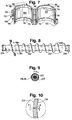
- Figure 8 shows a tube auger section 200 including flighting 202 on its outer surface. Attached to one axial end of the tube 200 is a male collar 204, and attached to the other end is a female collar 206. Other combinations of coupling collars, or plain ends, may be attached to the ends of the tube depending on the application and assembly of the series of tube sections.
- Slots 208 are provided in tube section 200.
- the slots are parallel to the longitudinal axis of the tube 200, that is, they are vertical in the typical application where auger section 200 is being used to drill a vertical hole in the ground. In the embodiment shown, each slot 208 is approximately two inches long.
- Figure 9 is a cross-sectional view of tube 200 along line 9-9 of Figure 8.
- the slots 208 are spaced apart by an angle ⁇ about the circumference of tube section 200; in the example shown, ⁇ is 24 degrees.
- ⁇ is 24 degrees.
- the slots 208 are spaced at angular intervals about the circumference of the tube 200 and are offset axially from one another along a spiral path parallel to flighting 202. The effect of this spacing is to not reduce the structural integrity of the tube 200 as severely as the slots or other openings used in previously known augers.
- the vertical (i.e., axial), tapered slots have been found to be more resistant to plugging than horizontal (i.e., perpendicular to the tube axis) slots and non-tapered slots used in prior art sampling augers when drilling in many types of soil.
- each slot 208 is tapered. As shown in Figure 10, each slot tapers from a narrower width A at the outer surface 212 of tube 200 to a wider width B at the inner surface 210 of the interior bore of tube 200. For example, a slot 208 may taper from approximately 0.008 inch at the outer surface 212 of tube section 200 to approximately 0.030 inch at the inner surface 210 of the interior boa.
- the slots 208 are preferably formed by laser cutting. The preferred width of the slot at the inner surfaces and outer surfaces 210 and 212, respectively, depends in part on the wall thickness of the tube 200.
- widths at least as narrow as 0.003 inch and as wide as at least 0.015 inch also will work satisfactorily.
- the optimum width depends in part also on the type of soil or other material surrounding tube 200 in a particular application.
- the purpose of the slots 208 is to permit fluid to enter into the interior bore of tube 200 so as to collect a sample of ground water or other fluid at the desired drill depth(s).
- Tube sections having slots are used only at the desired depth(s) for monitoring or sampling fluid from the well.
- the majority of sections used in drilling the well are identical to tube sections 12 and 14 as shown in Figure 1 and do not have slots.
- Tube sections with the slots of the invention but without flighting may also be used, for example, for taking samples in a previously-drilled well.
Landscapes
- Life Sciences & Earth Sciences (AREA)
- Engineering & Computer Science (AREA)
- Geology (AREA)
- Mining & Mineral Resources (AREA)
- Chemical & Material Sciences (AREA)
- Dispersion Chemistry (AREA)
- Physics & Mathematics (AREA)
- Environmental & Geological Engineering (AREA)
- Fluid Mechanics (AREA)
- General Life Sciences & Earth Sciences (AREA)
- Geochemistry & Mineralogy (AREA)
- Earth Drilling (AREA)
Applications Claiming Priority (4)
| Application Number | Priority Date | Filing Date | Title |
|---|---|---|---|
| US07/937,979 US5269572A (en) | 1992-08-28 | 1992-08-28 | Apparatus and method for coupling elongated members |
| US937979 | 1992-08-28 | ||
| US970362 | 1992-11-02 | ||
| US07/970,362 US5372208A (en) | 1992-08-28 | 1992-11-02 | Tube section having slots for sampling |
Publications (1)
| Publication Number | Publication Date |
|---|---|
| EP0586992A1 true EP0586992A1 (en) | 1994-03-16 |
Family
ID=27130108
Family Applications (1)
| Application Number | Title | Priority Date | Filing Date |
|---|---|---|---|
| EP93113774A Withdrawn EP0586992A1 (en) | 1992-08-28 | 1993-08-27 | Tube section having slots for sampling |
Country Status (3)
| Country | Link |
|---|---|
| EP (1) | EP0586992A1 (ja) |
| JP (1) | JPH06158976A (ja) |
| MX (1) | MX9305163A (ja) |
Cited By (5)
| Publication number | Priority date | Publication date | Assignee | Title |
|---|---|---|---|---|
| CN1051136C (zh) * | 1994-07-22 | 2000-04-05 | 李庆辉 | 石油套管大角度梯形缝加工方法及设备 |
| EP1413709A2 (en) * | 2002-10-25 | 2004-04-28 | Weatherford/Lamb, Inc. | Down hole filter |
| EP1690580A1 (de) * | 2005-02-14 | 2006-08-16 | TPR Fiberdur GmbH & Co. KG | Filterrohr |
| GB2433116A (en) * | 2005-12-10 | 2007-06-13 | Endet Ltd | Sampling probe |
| US7458615B2 (en) * | 2003-10-03 | 2008-12-02 | Fisher & Paykel Healthcare Limited | Connector |
Citations (5)
| Publication number | Priority date | Publication date | Assignee | Title |
|---|---|---|---|---|
| US2401035A (en) * | 1944-01-26 | 1946-05-28 | Nobs Chemical Company | Well screen |
| US3357564A (en) * | 1964-09-22 | 1967-12-12 | Halliburton Co | Filtering apparatus and method of making it |
| US3502145A (en) * | 1968-01-30 | 1970-03-24 | Shell Oil Co | Oil well liner incorporating reinforcement coating |
| US4821818A (en) * | 1988-02-01 | 1989-04-18 | Micro Specialties Co., Inc. | Tube auger sections |
| US5095990A (en) * | 1990-10-26 | 1992-03-17 | Mobil Oil Corporation | Method and device for sand control |
-
1993
- 1993-08-25 MX MX9305163A patent/MX9305163A/es unknown
- 1993-08-27 JP JP21293593A patent/JPH06158976A/ja active Pending
- 1993-08-27 EP EP93113774A patent/EP0586992A1/en not_active Withdrawn
Patent Citations (5)
| Publication number | Priority date | Publication date | Assignee | Title |
|---|---|---|---|---|
| US2401035A (en) * | 1944-01-26 | 1946-05-28 | Nobs Chemical Company | Well screen |
| US3357564A (en) * | 1964-09-22 | 1967-12-12 | Halliburton Co | Filtering apparatus and method of making it |
| US3502145A (en) * | 1968-01-30 | 1970-03-24 | Shell Oil Co | Oil well liner incorporating reinforcement coating |
| US4821818A (en) * | 1988-02-01 | 1989-04-18 | Micro Specialties Co., Inc. | Tube auger sections |
| US5095990A (en) * | 1990-10-26 | 1992-03-17 | Mobil Oil Corporation | Method and device for sand control |
Non-Patent Citations (1)
| Title |
|---|
| G.O. SUMAN, JR.: "Sand Control-Part 4", WORLD OIL, vol. 180, no. 2, 1 February 1975 (1975-02-01), pages 33 - 39 * |
Cited By (15)
| Publication number | Priority date | Publication date | Assignee | Title |
|---|---|---|---|---|
| CN1051136C (zh) * | 1994-07-22 | 2000-04-05 | 李庆辉 | 石油套管大角度梯形缝加工方法及设备 |
| EP1413709A2 (en) * | 2002-10-25 | 2004-04-28 | Weatherford/Lamb, Inc. | Down hole filter |
| EP1413709A3 (en) * | 2002-10-25 | 2004-09-29 | Weatherford/Lamb, Inc. | Down hole filter |
| NO333758B1 (no) * | 2002-10-25 | 2013-09-16 | Weatherford Lamb | Brønnfilter, fremgangsmåte for fremstilling, samt fremgangsmåte for filtrering av brønnfluider. |
| US7458615B2 (en) * | 2003-10-03 | 2008-12-02 | Fisher & Paykel Healthcare Limited | Connector |
| EP1690580A1 (de) * | 2005-02-14 | 2006-08-16 | TPR Fiberdur GmbH & Co. KG | Filterrohr |
| GB2433122B (en) * | 2005-12-10 | 2008-07-23 | Endet Ltd | Gas sampling probe |
| US8424396B2 (en) | 2005-12-10 | 2013-04-23 | Endet Ltd | Gas probes |
| GB2433116A (en) * | 2005-12-10 | 2007-06-13 | Endet Ltd | Sampling probe |
| CN104833445A (zh) * | 2005-12-10 | 2015-08-12 | 恩迪特有限公司 | 气体探针 |
| US9528917B2 (en) | 2005-12-10 | 2016-12-27 | Endet Ltd | Gas probes |
| US9766163B2 (en) | 2005-12-10 | 2017-09-19 | Endet Ltd. | Gas probes |
| CN104833445B (zh) * | 2005-12-10 | 2019-03-19 | 恩迪特有限公司 | 气体探针 |
| US10712243B2 (en) | 2005-12-10 | 2020-07-14 | Endet Limited | Gas probes |
| US11105716B2 (en) | 2005-12-10 | 2021-08-31 | Orbital Energy Group, Inc. | Gas probes |
Also Published As
| Publication number | Publication date |
|---|---|
| MX9305163A (es) | 1994-03-31 |
| JPH06158976A (ja) | 1994-06-07 |
Similar Documents
| Publication | Publication Date | Title |
|---|---|---|
| US5372208A (en) | Tube section having slots for sampling | |
| US4821818A (en) | Tube auger sections | |
| EP0167499B1 (en) | A coupling for connecting metal tubes end-to-end, particularly in marine pilings | |
| US4844516A (en) | Connector for coil tubing or the like | |
| US5332049A (en) | Composite drill pipe | |
| EP2038510B1 (en) | Stabbing guide adapted for use with saver sub | |
| AU777129B2 (en) | Inflatable packer with feed-thru conduits | |
| US4687232A (en) | Pipe slip joint system | |
| US20060032629A1 (en) | Insertion tube methods and apparatus | |
| US5588818A (en) | Rotor-to-rotor coupling | |
| US4522431A (en) | Self-aligning connector assembly | |
| AU6528498A (en) | Friction reducing tool | |
| JPS59155685A (ja) | 管継手 | |
| EP0586992A1 (en) | Tube section having slots for sampling | |
| EA001956B1 (ru) | Соединение бурильных труб | |
| EP0300739A2 (en) | Improved inner pipe member for dual-wall drill pipe assembly | |
| WO2015179906A1 (en) | Drill pipe rod for air rotary drilling | |
| CA2104987A1 (en) | Tube section having slots for sampling | |
| US4685895A (en) | Stabilizer mechanism for use in drilling deviated well bores | |
| GB2276217A (en) | A connector with a dowel device for connecting rotary drill casings | |
| US20200318441A1 (en) | Auger arrangement | |
| DE19749007A1 (de) | Vorrichtung zum Verbinden eines Nachziehrohres mit einem Ziehgerät | |
| EP4353943A2 (en) | Drill string joint for horizontal directional drilling system | |
| USRE26938E (en) | Rassieur sealed drill-string joint | |
| JP2001200535A (ja) | 鋼管杭の縦継ぎ装置 |
Legal Events
| Date | Code | Title | Description |
|---|---|---|---|
| PUAI | Public reference made under article 153(3) epc to a published international application that has entered the european phase |
Free format text: ORIGINAL CODE: 0009012 |
|
| AK | Designated contracting states |
Kind code of ref document: A1 Designated state(s): AT BE CH DE DK ES FR GB GR IE IT LI LU MC NL PT SE |
|
| STAA | Information on the status of an ep patent application or granted ep patent |
Free format text: STATUS: THE APPLICATION IS DEEMED TO BE WITHDRAWN |
|
| 18D | Application deemed to be withdrawn |
Effective date: 19940917 |