EP0586325B1 - Method and apparatus for TIG welding - Google Patents
Method and apparatus for TIG welding Download PDFInfo
- Publication number
- EP0586325B1 EP0586325B1 EP93610045A EP93610045A EP0586325B1 EP 0586325 B1 EP0586325 B1 EP 0586325B1 EP 93610045 A EP93610045 A EP 93610045A EP 93610045 A EP93610045 A EP 93610045A EP 0586325 B1 EP0586325 B1 EP 0586325B1
- Authority
- EP
- European Patent Office
- Prior art keywords
- welding
- positive
- arc
- workpiece
- period
- Prior art date
- Legal status (The legal status is an assumption and is not a legal conclusion. Google has not performed a legal analysis and makes no representation as to the accuracy of the status listed.)
- Expired - Lifetime
Links
- 238000003466 welding Methods 0.000 title claims abstract description 141
- 238000000034 method Methods 0.000 title claims abstract description 33
- 239000004411 aluminium Substances 0.000 claims description 8
- 229910052782 aluminium Inorganic materials 0.000 claims description 8
- XAGFODPZIPBFFR-UHFFFAOYSA-N aluminium Chemical compound [Al] XAGFODPZIPBFFR-UHFFFAOYSA-N 0.000 claims description 8
- 229910000838 Al alloy Inorganic materials 0.000 claims description 5
- 230000000694 effects Effects 0.000 claims description 5
- 229910052751 metal Inorganic materials 0.000 claims description 5
- 239000002184 metal Substances 0.000 claims description 5
- 238000004904 shortening Methods 0.000 claims 1
- PNEYBMLMFCGWSK-UHFFFAOYSA-N Alumina Chemical compound [O-2].[O-2].[O-2].[Al+3].[Al+3] PNEYBMLMFCGWSK-UHFFFAOYSA-N 0.000 description 20
- 230000006870 function Effects 0.000 description 11
- WFKWXMTUELFFGS-UHFFFAOYSA-N tungsten Chemical compound [W] WFKWXMTUELFFGS-UHFFFAOYSA-N 0.000 description 8
- 229910052721 tungsten Inorganic materials 0.000 description 8
- 239000010937 tungsten Substances 0.000 description 8
- 229960005363 aluminium oxide Drugs 0.000 description 6
- 230000008878 coupling Effects 0.000 description 6
- 238000010168 coupling process Methods 0.000 description 6
- 238000005859 coupling reaction Methods 0.000 description 6
- 230000008569 process Effects 0.000 description 6
- 238000004140 cleaning Methods 0.000 description 4
- 238000010586 diagram Methods 0.000 description 4
- 230000008901 benefit Effects 0.000 description 3
- 230000008859 change Effects 0.000 description 3
- 230000001105 regulatory effect Effects 0.000 description 3
- 230000001419 dependent effect Effects 0.000 description 2
- 239000004020 conductor Substances 0.000 description 1
- 230000006872 improvement Effects 0.000 description 1
- 238000004021 metal welding Methods 0.000 description 1
- 230000010363 phase shift Effects 0.000 description 1
- 230000009467 reduction Effects 0.000 description 1
- 230000000087 stabilizing effect Effects 0.000 description 1
- 230000001960 triggered effect Effects 0.000 description 1
Images


Classifications
-
- B—PERFORMING OPERATIONS; TRANSPORTING
- B23—MACHINE TOOLS; METAL-WORKING NOT OTHERWISE PROVIDED FOR
- B23K—SOLDERING OR UNSOLDERING; WELDING; CLADDING OR PLATING BY SOLDERING OR WELDING; CUTTING BY APPLYING HEAT LOCALLY, e.g. FLAME CUTTING; WORKING BY LASER BEAM
- B23K9/00—Arc welding or cutting
- B23K9/09—Arrangements or circuits for arc welding with pulsed current or voltage
- B23K9/091—Arrangements or circuits for arc welding with pulsed current or voltage characterised by the circuits
-
- B—PERFORMING OPERATIONS; TRANSPORTING
- B23—MACHINE TOOLS; METAL-WORKING NOT OTHERWISE PROVIDED FOR
- B23K—SOLDERING OR UNSOLDERING; WELDING; CLADDING OR PLATING BY SOLDERING OR WELDING; CUTTING BY APPLYING HEAT LOCALLY, e.g. FLAME CUTTING; WORKING BY LASER BEAM
- B23K9/00—Arc welding or cutting
- B23K9/06—Arrangements or circuits for starting the arc, e.g. by generating ignition voltage, or for stabilising the arc
- B23K9/073—Stabilising the arc
- B23K9/0738—Stabilising of the arc by automatic re-ignition means
Definitions
- the invention relates to a method of TIG welding ( T ungsten I nert G as-Welding) with a welding apparatus which receives alternating current from an alternating voltage source in such a manner that by a welding current between a welding electrode and a workpiece of metal, such as aluminium and aluminium alloys, that are to be welded, an arc is lit, the polarity of which changes synchronously with the frequency of the alternating voltage source between positive and negative periods i relation to the workpiece to be welded, where the polarity of the welding current between the welding electrode and the workpiece is controlled by an electronic control unit, and where the welding apparatus comprises a controllable inverter-based current source as well as means of re-igniting the arc in the positive period, i.e. when the welding electrode has positive potential in relation to the workpiece to be welded.
- the invention relates to a TIG welding apparatus for use when executing the method dislosed, which welding apparatus is of the kind which receives alternating current from an alternating voltage source in such a manner that by a welding current between a welding electrode and a workpiece of metal, such as aluminium and aluminium alloys, that are to be welded, an arc is lit, the polarity of which changes synchronously with the frequency of the alternating voltage source between positive and negative periods in relation to the workpiece to be welded, where the polarity of the welding current between the welding electrode and the workpiece is controlled by an electronic control unit, and where the welding apparatus comprises a controllable inverter-based current source and an electronic control circuit as well as means of re-igniting the arc in the positive period, i.e. when the welding electrode has positive potential in relation to the workpiece to be welded.
- the welding apparatus comprises a controllable inverter-based current source and an electronic control circuit as well as means of re-igniting the arc in the positive period
- TIG arc welding with alternating current is used to a great extent for the welding of metals such as aluminium and aluminium alloys.
- a welding current between a welding electrode and a workpiece of metal to be welded an arc is lit which polarity of current and voltage changes traditionally with 50 or 60 Hz synchronously with the frequency of the power supply to which the welding equipment is connected.
- the positive half cycle i.e. when the welding electrode voltage is positive in relation to the workpiece, for cleaning the workpiece by removing the aluminium-oxide layer on the surface of the workpiece, and the negative half cycle is used to heat the workpiece so that a "weldpool" is formed.
- the positive half cycle approx. 1/3 of the power is dissipated in the workpiece and approx. 2/3 of the power is dissipated in the tungsten electrode.
- the negative half cycle approx. 2/3 of the power is dissipated in the workpiece and approx. 1/3 of the power is dissipated in the tungsten electrode.
- the arc When the polarity is changed, the arc must be re-ignited i.e. re-lit. This occurs easily when the change is from positive to negative polarity, in that the electrode is hot and easily emits electrons, whereas it is difficult to change from the negative polarity to positive polarity.
- the electrode is hotter than the weldpool, but also because pure aluminium does not easily emit electrons.
- the energy required for the emission of electrons from aluminium is very high, and since aluminium oxide is electrically insulating, such a current source must necessarily be equipped with a circuit which imparts a brief pulse with high voltage to the welding circuit in order to re-establish the positive half cycle.
- weldpool It is also necessary for the weldpool to be completely cleansed of aluminium oxide in order to achieve a satisfactory weld quality.
- many welding current sources are equipped with a regulating element whereby it is possible to adjust the relationship between the time for which the polarity of the tungsten electrode is positive and the time for which the polarity is negative.
- a regulator element enables the cleansing effect to be regulated.
- European patent no. 0 078 252 describes an inverter-based welding current source where a for example a microprocessor is applied for the control.
- this welding current source runs only by direct current and therefore it has no polarity control. Therefore, the known welding current source is of another type than that of the technique described in the introductory part.
- control unit is arranged to measure continuously whether the arc is lit or not and to shorten the length of the positive period, if the arc is not re-ignited in the positive periode.
- the welding current source is arranged in such a manner that the polarity of the welding current is controlled from a control unit by means of one or more signals, so that it is possible to regulate the frequency of the AC balance, i.e. the relationship between the time for which the polarity of the tungsten electrode is positive and the time for which it is negative.
- the control circuit according to the invention will thus not be operative.
- the period is shortened in that an immediate shift to the negative polarity takes place. The principle is thus that if an arc can not be established during the positive period, this is because there is no need for cleaning and thus there is no reason to wait before changing to negative polarity.
- the stabilizing effect and the herewith increased welding quality is achieved by ensuring a more constant supply of energy to the arc than is the case with the known welding processes.
- the dependent claims 2-5 disclose advantageous methods of TIG welding with which the improved arc stability and optimum welding quality can be achieved.
- the object is obtained with a welding apparatus as disclosed which welding apparatus according to the invention er characteristic in that the control unit is arranged to measure continously whether the arc is lit or not, that the control circuit continously monitors the control unit of the welding apparatus to ascertain whether the arc is lit or not, and that the control circuit is arranged to control the inverter of the welding apparatus, so that the length of the positive period is shortened, if the arc is not re-ignited when the welding electrode has positive polarity in relation to the workpiece.
- TIG welding apparatus ensures in a simple manner an optimum welding quality at varying amount of oxide on the surface of the workpiece to be welded.
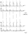
- FIG. 1 Uppermost in fig. 1 is shown the welding voltage U as a function of the time, and lowermost the welding current I as a function of the time, and as they appear in a known welding machine without use of the method according to the invention.
- the figure shows six voltage periods numbered 1-6 with corresponding current periods. In order to achieve ignition in the positive periods, each period starts with an ignition voltage pulse 7 which is higher than both the welding voltage and the no-load voltage of the welding current source.
- ignition voltage pulse 7 which is higher than both the welding voltage and the no-load voltage of the welding current source.
- Such means for the re-ignition of the arc in the positive periods are known, and therefore they will not be dealt with in more detail. It will be seen in the first three periods that correct re-ignition occurs both in the positive part and in the negative part of each period. The welding voltage and welding current are therefore completely normal and as desired.
- Fig. 2 shows welding voltage and welding current as a function of the time when use is made of the method according to the invention, e.g. during the use of one of the welding current sources described later.
- Fig. 2 shows the same six periods as in fig. 1, and it will be seen that no re-ignition occurs in the positive parts of the 4th and 5th periods, and for this reason the positive period is shortened so that the time for which the current is 0 is shortened.
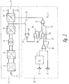
- the reference number 10 indicates an inverter-based welding machine of a known type which functions in accordance with the method which was described in connection with fig. 1.
- the welding machine or the welding current source 10 receives normal 3-phased alternating current 11 from a mains supply, and the power is fed to an AC/DC converter 12, normally a 3-phase rectifier. From here, the DC output power is fed to a DC/AC converter 13, the output voltage of which is shown as square-wave pulses, e.g. with a frequency in the order of 50 kHz.
- the output power is fed to a transformer 14 and further to an AC/DC converter 15. In this manner, a desired DC voltage level is achieved by using a transformer 14 of minimum size, and thus the usually very large and heavy welding transformers are avoided.
- the DC power is then fed to a DC/AC converter 16 which is configured as a controllable inverter coupling, the output frequency of which can be regulated, e.g. from 5 Hz to 500 Hz.
- the electronic control circuits and measuring circuits in the converters are normally arranged in such a way that the strength of the current and the frequency are constantly monitored, and thus the circuits can instantly register if there is no flow of welding current in the welding circuit 17 between the output 17'and 17'', where for example the output 17' is the tungsten electrode in the TIG welding arrangement and 17'' is the electrical conductor which leads to the workpiece.
- the welding current source is normally provided with means of regulation, whereby it is possible to adjust the relationship between the time for which the polarity of the tungsten electrode is positive and the time for which the polarity is negative, so that the welding machine operator himself can adjust the cleaning effect.
- a circuit 20 is added which, via the lead 21, senses whether or not a re-ignition has occurred in the positive period. If a re-ignition has occurred, the control circuit 20 does not have any influence on the welding process. On the other hand, if re-ignition has not occurred, the control circuit 20 will react and will transmit a signal via the lead 22. This signal will instantly ensure that the welding voltage changes from positive to negative potential, cf. the explanation in connection with fig. 2
- the control circuit 20 comprises an oscillator 29 with frequency adjustment elements 30, so that an adjustable saw-tooth voltage is fed to the comparator 28, to which there is also fed a balance signal from a balance regulation element 31. There is hereby generated the control voltage which ensures the welding voltage changes in the controllable inverter 16.
- the output signal from the comparator 28 is fed to a logical circuit 25, which forms part of a latch coupling 24, and also to a logical circuit 32.
- the lead 21 is connected via a comparator 23 to the other input of the latch coupling 24.
- the comparator 23 is coupled to a reference voltage which can be adjustable.
- the control circuit 20 functions as follows: When a signal is received at the latch coupling 24 via the lead 21 and the comparator 23, this indicates that no reignition has occurred in the positive period, and the logical circuit 32 immediately switches over so that a changeover of the welding voltage takes place via the lead 22. If there is no signal from the comparator 23, the latch coupling 24 is not triggered and the control signal from the comparator 28 passes via the lead 33 directly to the logical circuit 32. Consequently, there is no changeover of the welding voltage from positive to negative polarity until the welding current sequence has been as long as determined by the adjusting elements 30, 31.
- a programmable microprocessor is inserted in the welding machine 10, which is suitably programmed in an appropriate programming language so that the logical function diagram in fig. 4 is followed.
- Fig. 5 shows chronologically the changeover of the welding voltage, in that t pos indicates the period of time for which the voltage is positive and t neg indicates the period of time for which the voltage is negative.
- t pos 1 f ⁇ (100 - B) 100
- t neg 1 f ⁇ B 100
- the electronic switch in the inverter coupling 16 is hereby changed over by means of the microprocessor following the same function as explained in connection with figs. 2 and 3 of the drawing.
- the fully-drawn line in fig. 5 shows the chronological sequence of the welding voltage when the welding takes place in a normal manner, i.e. with total re-ignition both in the positive and the negative periods
- the dotted line in fig. 5 shows the chronological sequence of the welding voltage when no re-ignition occurs in the positive period, and the changeover of the welding voltage takes place in accordance with the logical function diagram in fig. 4 or the control circuit 20 in fig. 3.
Landscapes
- Engineering & Computer Science (AREA)
- Physics & Mathematics (AREA)
- Plasma & Fusion (AREA)
- Mechanical Engineering (AREA)
- Arc Welding In General (AREA)
- Arc Welding Control (AREA)
Abstract
Description
- The invention relates to a method of TIG welding (TungstenInertGas-Welding) with a welding apparatus which receives alternating current from an alternating voltage source in such a manner that by a welding current between a welding electrode and a workpiece of metal, such as aluminium and aluminium alloys, that are to be welded, an arc is lit, the polarity of which changes synchronously with the frequency of the alternating voltage source between positive and negative periods i relation to the workpiece to be welded, where the polarity of the welding current between the welding electrode and the workpiece is controlled by an electronic control unit, and where the welding apparatus comprises a controllable inverter-based current source as well as means of re-igniting the arc in the positive period, i.e. when the welding electrode has positive potential in relation to the workpiece to be welded.
- Furthermore, the invention relates to a TIG welding apparatus for use when executing the method dislosed, which welding apparatus is of the kind which receives alternating current from an alternating voltage source in such a manner that by a welding current between a welding electrode and a workpiece of metal, such as aluminium and aluminium alloys, that are to be welded, an arc is lit, the polarity of which changes synchronously with the frequency of the alternating voltage source between positive and negative periods in relation to the workpiece to be welded, where the polarity of the welding current between the welding electrode and the workpiece is controlled by an electronic control unit, and where the welding apparatus comprises a controllable inverter-based current source and an electronic control circuit as well as means of re-igniting the arc in the positive period, i.e. when the welding electrode has positive potential in relation to the workpiece to be welded.
- TIG arc welding with alternating current is used to a great extent for the welding of metals such as aluminium and aluminium alloys. By a welding current between a welding electrode and a workpiece of metal to be welded an arc is lit which polarity of current and voltage changes traditionally with 50 or 60 Hz synchronously with the frequency of the power supply to which the welding equipment is connected. Today, wide use is made of inverter-based current sources, and such a welding current source is a prerequisite for the present invention, in that it is hereby possible to adjust the welding machine for frequencies other than those mentioned of the alternating current which is used to transfer the energy to the welding arc.
- In the welding process, use is made of the positive half cycle, i.e. when the welding electrode voltage is positive in relation to the workpiece, for cleaning the workpiece by removing the aluminium-oxide layer on the surface of the workpiece, and the negative half cycle is used to heat the workpiece so that a "weldpool" is formed. During the positive half cycle, approx. 1/3 of the power is dissipated in the workpiece and approx. 2/3 of the power is dissipated in the tungsten electrode. During the negative half cycle, approx. 2/3 of the power is dissipated in the workpiece and approx. 1/3 of the power is dissipated in the tungsten electrode.
- When the polarity is changed, the arc must be re-ignited i.e. re-lit. This occurs easily when the change is from positive to negative polarity, in that the electrode is hot and easily emits electrons, whereas it is difficult to change from the negative polarity to positive polarity.
- This is partly due to the fact that the electrode is hotter than the weldpool, but also because pure aluminium does not easily emit electrons. The energy required for the emission of electrons from aluminium is very high, and since aluminium oxide is electrically insulating, such a current source must necessarily be equipped with a circuit which imparts a brief pulse with high voltage to the welding circuit in order to re-establish the positive half cycle. Moreover, it is necessary to emit electrons from the aluminium oxide which is constantly formed on the aluminium surface of the weldpool. This means that the positive half cycle can be established only if there are aluminium oxides within a certain radius from the tungsten electrode which is used to transfer the current to the workpiece. It is also necessary for the weldpool to be completely cleansed of aluminium oxide in order to achieve a satisfactory weld quality. In order to be able to adjust the cleansing effect so that it is appropriate for the relevant welding task, many welding current sources are equipped with a regulating element whereby it is possible to adjust the relationship between the time for which the polarity of the tungsten electrode is positive and the time for which the polarity is negative. Such a regulator element enables the cleansing effect to be regulated.
- A welding apparatus which uses the known technique explained above is known from USA patent no. 4,947,021.
- From USA patent no. 4,963,715 there is known another welding apparatus for TIG welding which is provided with a circuit which can detect whether or not the arc is re-ignited in the positive cycle. If the arc is not re-ignited, the ignition voltage is immediately increased to ensure that the arc is re-established.
- Furthermore, from USA patent no. 4,038,515 is known a method of TIG welding, where the frequency of the welding current is locked permanently to the frequency of the alternating voltage source, i.e. 50 Hz in Europe and 60 Hz in the U.S.A.
- It is impossible to regulate over each half-period, but for the physical reasons a half-period must have a minimum duration causing the half-period regulations to be limited to range from approx. 30 to 70 per cent of each half-period. This is due to the fact that the output voltage of the welding transformer must have a polarity corresponding to the desired polarity of the arc.
- If the arc is not re-ignited in the positive period it is impossible momentary to re-polarize, if so desired. It is necessary to await the phase shift of the welding transformer.
- The disadvantages of the above known techniques are imbedded in the fact that it is not possible to maintain a stable arc under varying welding conditions. Thus, none of the mentioned techniques seriously considers the varying amount of aluminium oxide on the surface of the weldpool and therefore they make attempts to maintain an arc even though there is no aluminium oxide on the surface of the weldpool.
- European patent no. 0 078 252 describes an inverter-based welding current source where a for example a microprocessor is applied for the control. However, this welding current source runs only by direct current and therefore it has no polarity control. Therefore, the known welding current source is of another type than that of the technique described in the introductory part.
- It is the object of the present invention to provide a method of welding and a welding apparatus with which an optimum welding quality is achieved which is of great practical importance.
- This object is achieved by a method of the kind described in the introductory part, which method according to the invention is characteristic in that the control unit is arranged to measure continuously whether the arc is lit or not and to shorten the length of the positive period, if the arc is not re-ignited in the positive periode.
- When using the method as disclosed and characterized in
claim 1, a more stable arc and herewith a better quality of weld can be achieved than with the known welding processes. It has proved namely that although the welding apparatus is adjusted for a reasonable amount of cleansing, it can happen that during the welding process the need for cleaning is reduced because the surface is not as oxidized as expected. This can happen for example if welding is carried out at a place where welding has taken place earlier, or if the electrode is held stationary or moved very slowly. The result of this is normally that the positive half period is not re-established every time, and the supply of energy to the weldpool becomes unstable. - Consequently, it is a prerequisite for the invention that the welding current source is arranged in such a manner that the polarity of the welding current is controlled from a control unit by means of one or more signals, so that it is possible to regulate the frequency of the AC balance, i.e. the relationship between the time for which the polarity of the tungsten electrode is positive and the time for which it is negative.
- According to the invention it is consequently registered whether or not the arc is ignited in the positive period. If ignition takes place, the welding is effected in a quite normal manner and the control circuit according to the invention will thus not be operative. On the other hand, if there is no ignition during the positive period, the period is shortened in that an immediate shift to the negative polarity takes place. The principle is thus that if an arc can not be established during the positive period, this is because there is no need for cleaning and thus there is no reason to wait before changing to negative polarity.
- Consequently, the stabilizing effect and the herewith increased welding quality is achieved by ensuring a more constant supply of energy to the arc than is the case with the known welding processes.
- The dependent claims 2-5 disclose advantageous methods of TIG welding with which the improved arc stability and optimum welding quality can be achieved.
- Furthermore, the object is obtained with a welding apparatus as disclosed which welding apparatus according to the invention er characteristic in that the control unit is arranged to measure continously whether the arc is lit or not, that the control circuit continously monitors the control unit of the welding apparatus to ascertain whether the arc is lit or not, and that the control circuit is arranged to control the inverter of the welding apparatus, so that the length of the positive period is shortened, if the arc is not re-ignited when the welding electrode has positive polarity in relation to the workpiece.
- TIG welding apparatus according to the invention ensures in a simple manner an optimum welding quality at varying amount of oxide on the surface of the workpiece to be welded.
- The dependent claims 7, 8, 9 and 10 disclose advantageous embodiments for the welding machine's electronic control circuit.
- The invention will now be described in more detail with reference to the drawing, in that
- fig. 1
- shows welding voltage and welding current as a function of the time for a known source of welding current,
- fig. 2
- shows welding voltage and welding current as a function of the time according to the invention,
- fig. 3
- shows a preferred configuration for the hardware solution according to the invention,
- fig. 4
- shows a preferred configuration for the software solution according to the invention, and
- fig. 5
- shows a pulse diagram for the welding current.
- The method according to the invention will now be described in more detail with reference to figs. 1 and 2 of the drawing. Uppermost in fig. 1 is shown the welding voltage U as a function of the time, and lowermost the welding current I as a function of the time, and as they appear in a known welding machine without use of the method according to the invention. The figure shows six voltage periods numbered 1-6 with corresponding current periods. In order to achieve ignition in the positive periods, each period starts with an
ignition voltage pulse 7 which is higher than both the welding voltage and the no-load voltage of the welding current source. Such means for the re-ignition of the arc in the positive periods are known, and therefore they will not be dealt with in more detail. It will be seen in the first three periods that correct re-ignition occurs both in the positive part and in the negative part of each period. The welding voltage and welding current are therefore completely normal and as desired. - In the 4th and 5th period no re-ignition occurs in the positive period, and the welding current is therefore 0 during the whole of the positive period and the welding machine stands with full no-load voltage. This results in a reduced supply of power to the arc and therewith the weldpool, and thus in a reduction of arc stability.
- In the 6th period, correct re-ignition is achieved in the positive period and the welding process is again quite normal.
- Fig. 2 shows welding voltage and welding current as a function of the time when use is made of the method according to the invention, e.g. during the use of one of the welding current sources described later. Fig. 2 shows the same six periods as in fig. 1, and it will be seen that no re-ignition occurs in the positive parts of the 4th and 5th periods, and for this reason the positive period is shortened so that the time for which the current is 0 is shortened.
- If it is ensured that the length of the positive period is shortened immediately that it is ascertained that the arc has not been re-established, it can be seen directly from fig. 2 that a very uniform supply of power to the arc is achieved.
- Consequently, with the method according to the invention, a significant improvement can be achieved in the stability of the arc.
- It will be an advantage for arc stability that the length of the negative period is held substantially constant when the positive period is shortened, and that the frequency of the welding current is also held substantially constant when the positive period is shortened.
- From the current curve in fig. 2 it will be seen that in periods where no re-ignition of the arc takes place in the positive part of the period, there can occur a minor change in the supply of energy to the arc in relation to the energy which is supplied under normal welding conditions, i.e. when a normal re-ignition takes place, which is why it can be of advantage to correct the strength of the welding current so that the power which is supplied is held substantially constant, in that this gives the maximum arc stability.
- In practice it has proved possible to achieve the desired effect with the method according to the invention with different welding machine embodiments. In the following will be described two embodiments, i.e. a hardware solution as shown in fig. 3 and a software solution as shown in figs. 4 and 5.
- In fig. 3 the
reference number 10 indicates an inverter-based welding machine of a known type which functions in accordance with the method which was described in connection with fig. 1. The welding machine or the weldingcurrent source 10 receives normal 3-phased alternating current 11 from a mains supply, and the power is fed to an AC/DC converter 12, normally a 3-phase rectifier. From here, the DC output power is fed to a DC/AC converter 13, the output voltage of which is shown as square-wave pulses, e.g. with a frequency in the order of 50 kHz. The output power is fed to atransformer 14 and further to an AC/DC converter 15. In this manner, a desired DC voltage level is achieved by using atransformer 14 of minimum size, and thus the usually very large and heavy welding transformers are avoided. - The DC power is then fed to a DC/
AC converter 16 which is configured as a controllable inverter coupling, the output frequency of which can be regulated, e.g. from 5 Hz to 500 Hz. - The electronic control circuits and measuring circuits in the converters are normally arranged in such a way that the strength of the current and the frequency are constantly monitored, and thus the circuits can instantly register if there is no flow of welding current in the
welding circuit 17 between the output 17'and 17'', where for example the output 17' is the tungsten electrode in the TIG welding arrangement and 17'' is the electrical conductor which leads to the workpiece. In addition, the welding current source is normally provided with means of regulation, whereby it is possible to adjust the relationship between the time for which the polarity of the tungsten electrode is positive and the time for which the polarity is negative, so that the welding machine operator himself can adjust the cleaning effect. - For the execution of the method according to the invention, a
circuit 20 is added which, via thelead 21, senses whether or not a re-ignition has occurred in the positive period. If a re-ignition has occurred, thecontrol circuit 20 does not have any influence on the welding process. On the other hand, if re-ignition has not occurred, thecontrol circuit 20 will react and will transmit a signal via thelead 22. This signal will instantly ensure that the welding voltage changes from positive to negative potential, cf. the explanation in connection with fig. 2 - The
control circuit 20 comprises anoscillator 29 withfrequency adjustment elements 30, so that an adjustable saw-tooth voltage is fed to thecomparator 28, to which there is also fed a balance signal from abalance regulation element 31. There is hereby generated the control voltage which ensures the welding voltage changes in thecontrollable inverter 16. The output signal from thecomparator 28 is fed to alogical circuit 25, which forms part of alatch coupling 24, and also to alogical circuit 32. - The
lead 21 is connected via acomparator 23 to the other input of thelatch coupling 24. For level adjustment, thecomparator 23 is coupled to a reference voltage which can be adjustable. - The
control circuit 20 functions as follows:
When a signal is received at thelatch coupling 24 via thelead 21 and thecomparator 23, this indicates that no reignition has occurred in the positive period, and thelogical circuit 32 immediately switches over so that a changeover of the welding voltage takes place via thelead 22. If there is no signal from thecomparator 23, thelatch coupling 24 is not triggered and the control signal from thecomparator 28 passes via thelead 33 directly to thelogical circuit 32. Consequently, there is no changeover of the welding voltage from positive to negative polarity until the welding current sequence has been as long as determined by the adjustingelements - In figs. 4 and 5 is shown a logical function diagram for a software solution. Instead of the
control circuit 20, a programmable microprocessor is inserted in thewelding machine 10, which is suitably programmed in an appropriate programming language so that the logical function diagram in fig. 4 is followed. - Fig. 5 shows chronologically the changeover of the welding voltage, in that tpos indicates the period of time for which the voltage is positive and tneg indicates the period of time for which the voltage is negative.

- f =
- frequency [Hz]
- B =
- balance [%]
- The electronic switch in the
inverter coupling 16 is hereby changed over by means of the microprocessor following the same function as explained in connection with figs. 2 and 3 of the drawing. - The fully-drawn line in fig. 5 shows the chronological sequence of the welding voltage when the welding takes place in a normal manner, i.e. with total re-ignition both in the positive and the negative periods, and the dotted line in fig. 5 shows the chronological sequence of the welding voltage when no re-ignition occurs in the positive period, and the changeover of the welding voltage takes place in accordance with the logical function diagram in fig. 4 or the
control circuit 20 in fig. 3.
Claims (10)
- Method of TIG welding with a welding apparatus (10) which receives alternating current from an alternating voltage source (11) in such a manner that by a welding current (17) between a welding electrode (17') and a workpiece (17'') of metal, such as aluminium and aluminium alloys, that are to be welded, an arc is lit, the polarity of which changes synchronously with the frequency of the alternating voltage source (11) between positive and negative periods in relation to the workpiece (17'') to be welded, where the polarity of the welding current (17) between the welding electrode (17') and the workpiece (17'') is controlled by an electronic control unit, and where the welding apparatus (10) comprises a controllable inverter-based current source (16) as well as means of reigniting the arc in the positive periods, i.e. when the welding electrode (17') has positive potential in relation to the workpiece (17'') to be welded, characterized in that the control unit is arranged to measure continuously whether the arc is lit or not and to shorten the length of the positive periods, in which the arc has not been re-ignited.
- Method according to claim 1, characterized in that the length of the positive period is shortened immediately when it is ascertained that the arc is not lit in the positive period.
- Method according to claim 1 or 2, characterized in that the length of the negative period is held substantially constant when the positive period is shortened.
- Method according to claim 1 or 2, characterized in that the frequency of the welding current is held substantially constant when the positive period is shortened.
- Method according to claim 3 or 4, characterized in that the intensity of the welding current is corrected in such a manner that the power which is supplied to the workpiece is held substantially constant when no ignition occurs in the positive period.
- TIG welding apparatus for use when executing the method of TIG welding according to claim 1, which welding apparatus (10) is of the kind which receives alternating current from an alternating voltage source (11) in such a manner that at a welding current (17) between a welding electrode (17') and a workpiece (17'') of metal, such as aluminium and aluminium alloys, that are to be welded, an arc is lit, the polarity of which changes synchronously with the frequency of the alternating voltage source (11) between positive and negative periods in relation to the workpiece (17'') to be welded, where the polarity of the welding current between the welding electrode (17') and the workpiece (17'') is controlled by an electronic control unit, and where the welding apparatus (10) comprises a controllable inverter-based current source (16) as well as means of re-igniting the arc in the positive periods, i.e. when the welding electrode has positive potential in relation to the workpiece (17'') to be welded, characterized in that the control unit is arranged to measure continuously whether the arc is lit or not, that the electronic control circuit (20) continuously monitors the control unit of the welding apparatus (10) to ascertain whether the arc is lit or not, and that the control circuit (20) is arranged to control the inverter (16) of the welding apparatus (10), so that the length of the positive periods, in which the arc has not been re-ignited is shortened.
- Welding apparatus according to claim 6, characterized in that the electronic control circuit (20) comprises an oscillator (29) and means (30) for the regulation of the oscillator frequency, and means (31) for the regulation of the balance, i.e. the relationship between the time for which the welding voltage is positive and negative.
- Welding apparatus according to claim 7, characterized in that the control circuit comprises a logical circuit (25,32) which is arranged in such a manner that control signals for the adjustment of the balance are led via a bypass (33) directly to the inverter (16) when the control circuit has ascertained that the arc has been re-ignited in the positive period.
- Welding apparatus according to claim 6 characterized in that the electronic control circuit (20) comprises a microprocessor with memory in which there is stored a control program which is arranged to control the microprocessor so that it continuously monitors the welding machine's control unit, and sends signals hereto to effect the shortening of the positive period if the microprocessor ascertains that the arc has not been re-ignited in the positive period.
- Welding apparatus according to any of the claims 6-9, characterized in that it comprises means which are arranged to measure or calculate the power which is supplied to the workpiece, and to regulate the magnitude of said power.
Applications Claiming Priority (2)
| Application Number | Priority Date | Filing Date | Title |
|---|---|---|---|
| DK107392A DK172238B1 (en) | 1992-08-28 | 1992-08-28 | Method and apparatus for TIG welding |
| DK1073/92 | 1992-08-28 |
Publications (3)
| Publication Number | Publication Date |
|---|---|
| EP0586325A2 EP0586325A2 (en) | 1994-03-09 |
| EP0586325A3 EP0586325A3 (en) | 1994-08-10 |
| EP0586325B1 true EP0586325B1 (en) | 1997-06-04 |
Family
ID=8100685
Family Applications (1)
| Application Number | Title | Priority Date | Filing Date |
|---|---|---|---|
| EP93610045A Expired - Lifetime EP0586325B1 (en) | 1992-08-28 | 1993-08-10 | Method and apparatus for TIG welding |
Country Status (5)
| Country | Link |
|---|---|
| US (1) | US5365035A (en) |
| EP (1) | EP0586325B1 (en) |
| AT (1) | ATE153891T1 (en) |
| DE (1) | DE69311234T2 (en) |
| DK (1) | DK172238B1 (en) |
Cited By (1)
| Publication number | Priority date | Publication date | Assignee | Title |
|---|---|---|---|---|
| EP3825051A1 (en) | 2019-11-21 | 2021-05-26 | FRONIUS INTERNATIONAL GmbH | Method and device for welding with a non-consumable electrode |
Families Citing this family (8)
| Publication number | Priority date | Publication date | Assignee | Title |
|---|---|---|---|---|
| DK172238B1 (en) * | 1992-08-28 | 1998-02-02 | Migatronic Svejsemask | Method and apparatus for TIG welding |
| DE19720875A1 (en) * | 1997-05-17 | 1998-11-19 | Rehm Gmbh U Co Schweistechnik | Method and apparatus for controlling the welding current during TIG welding |
| US6087628A (en) * | 1997-06-16 | 2000-07-11 | Illinois Tool Works Inc. | Method and apparatus for controlling a welding power supply |
| US5990443A (en) * | 1998-03-12 | 1999-11-23 | Thermal Dynamics Corporation | Plasma torch pilot arc circuit |
| EP2431119B2 (en) | 2010-02-23 | 2024-08-07 | Panasonic Intellectual Property Management Co., Ltd. | Alternating-current welding method and alternating-current welding device |
| EP2684634B1 (en) * | 2012-07-09 | 2020-02-12 | Cloos Innovations-GmbH | AC metal protective gas welding method with continually fed welding wire |
| US10052706B2 (en) * | 2014-04-04 | 2018-08-21 | Lincoln Global, Inc. | Method and system to use AC welding waveform and enhanced consumable to improve welding of galvanized workpiece |
| JP6882832B2 (en) * | 2017-09-26 | 2021-06-02 | 株式会社ダイヘン | AC non-consumable electrode arc welding control method |
Citations (1)
| Publication number | Priority date | Publication date | Assignee | Title |
|---|---|---|---|---|
| US5365035A (en) * | 1992-08-28 | 1994-11-15 | Svejsemaskinefabrikken Migatronic A/S | Method and apparatus for TIG welding |
Family Cites Families (7)
| Publication number | Priority date | Publication date | Assignee | Title |
|---|---|---|---|---|
| US3895212A (en) * | 1972-05-10 | 1975-07-15 | Babcock & Wilcox Co | Fusion welding |
| GB1492311A (en) * | 1975-03-06 | 1977-11-16 | Atomic Energy Authority Uk | Electric arc-welding processes and apparatus therefor |
| US4038515A (en) * | 1975-05-08 | 1977-07-26 | Miller Electric Manufacturing Company | Asymmetrical a.c. welder |
| DE2658724A1 (en) * | 1976-12-24 | 1978-06-29 | Interatom | Welding transformer current source - has current controller connected by switches to inverter control inputs for different load current directions |
| EP0078252B1 (en) * | 1981-10-27 | 1987-12-09 | Fronius Schweissmaschinen Kg Austria | Electronic welding device |
| US4947021A (en) * | 1987-12-29 | 1990-08-07 | The Lincoln Electric Company | Method and apparatus for TIG welding |
| US4963715A (en) * | 1989-03-27 | 1990-10-16 | Venable Industries, Inc. | Variable polarity power supply for welding |
-
1992
- 1992-08-28 DK DK107392A patent/DK172238B1/en not_active IP Right Cessation
-
1993
- 1993-08-10 EP EP93610045A patent/EP0586325B1/en not_active Expired - Lifetime
- 1993-08-10 DE DE69311234T patent/DE69311234T2/en not_active Expired - Fee Related
- 1993-08-10 AT AT93610045T patent/ATE153891T1/en not_active IP Right Cessation
- 1993-08-18 US US08/108,998 patent/US5365035A/en not_active Expired - Fee Related
Patent Citations (1)
| Publication number | Priority date | Publication date | Assignee | Title |
|---|---|---|---|---|
| US5365035A (en) * | 1992-08-28 | 1994-11-15 | Svejsemaskinefabrikken Migatronic A/S | Method and apparatus for TIG welding |
Cited By (3)
| Publication number | Priority date | Publication date | Assignee | Title |
|---|---|---|---|---|
| EP3825051A1 (en) | 2019-11-21 | 2021-05-26 | FRONIUS INTERNATIONAL GmbH | Method and device for welding with a non-consumable electrode |
| WO2021099541A1 (en) | 2019-11-21 | 2021-05-27 | Fronius International Gmbh | Method and device for welding by means of a non-consumable electrode |
| US11504792B2 (en) | 2019-11-21 | 2022-11-22 | Fronius International Gmbh | Method and device for welding by means of a non-consumable electrode |
Also Published As
| Publication number | Publication date |
|---|---|
| EP0586325A2 (en) | 1994-03-09 |
| DE69311234T2 (en) | 1997-11-13 |
| ATE153891T1 (en) | 1997-06-15 |
| DE69311234D1 (en) | 1997-07-10 |
| EP0586325A3 (en) | 1994-08-10 |
| DK107392D0 (en) | 1992-08-28 |
| DK172238B1 (en) | 1998-02-02 |
| DK107392A (en) | 1994-03-01 |
| US5365035A (en) | 1994-11-15 |
Similar Documents
| Publication | Publication Date | Title |
|---|---|---|
| US6051806A (en) | Power supply apparatus for welders and method of manufacturing same | |
| EP0607819B1 (en) | Pulsed arc welding apparatus having a consumable electrode wire | |
| US5349159A (en) | Consumable-electrode AC gas shield arc welding method and apparatus therefor | |
| US6034350A (en) | Method and apparatus for initiating a welding arc using a background circuit | |
| US4485293A (en) | Short circuit transfer arc welding machine | |
| EP0947276B1 (en) | Method of and apparatus for initiating a welding arc | |
| EP0586325B1 (en) | Method and apparatus for TIG welding | |
| EP0715921A2 (en) | Apparatus for controlling a consumable electrode pulsed-arc welding power source | |
| EP0787555B1 (en) | Welding power control apparatus for consumable-electrode type pulse arc welding and a method therefor | |
| RU2293000C2 (en) | Two-stage electric arc welding set and method of electric arc welding (versions) | |
| JPH08300156A (en) | AC plasma arc welder | |
| JPS569064A (en) | Method and device of arc starting of electrode consuming arc welding machine | |
| US3524041A (en) | Electric arc process and apparatus | |
| JPH03474A (en) | Method for controlling output of consumable electrode arc welding power source | |
| JP2873716B2 (en) | Starting AC arc | |
| JP2854613B2 (en) | AC arc welding method and apparatus for consumable electrode type gas shielded arc welding | |
| JPH0747208B2 (en) | Consumable electrode type arc welder | |
| JPS5886978A (en) | Arc welding device | |
| JP2512911B2 (en) | Arc welding machine | |
| JP2584140B2 (en) | AC TIG welding machine | |
| JPS58107268A (en) | Arc welding device using nonconsumable electrode | |
| JPS5890376A (en) | Arc welding device | |
| KR960004790B1 (en) | Capacity control apparatus and method of an arc welding machine | |
| JP2711137B2 (en) | AC TIG welding equipment | |
| JP3202828B2 (en) | Power control method of consumable electrode type gas shielded arc welding and welding device therefor |
Legal Events
| Date | Code | Title | Description |
|---|---|---|---|
| PUAI | Public reference made under article 153(3) epc to a published international application that has entered the european phase |
Free format text: ORIGINAL CODE: 0009012 |
|
| AK | Designated contracting states |
Kind code of ref document: A2 Designated state(s): AT BE CH DE ES FR GB IT LI NL SE |
|
| PUAL | Search report despatched |
Free format text: ORIGINAL CODE: 0009013 |
|
| AK | Designated contracting states |
Kind code of ref document: A3 Designated state(s): AT BE CH DE ES FR GB IT LI NL SE |
|
| 17P | Request for examination filed |
Effective date: 19941203 |
|
| 17Q | First examination report despatched |
Effective date: 19951121 |
|
| GRAG | Despatch of communication of intention to grant |
Free format text: ORIGINAL CODE: EPIDOS AGRA |
|
| GRAH | Despatch of communication of intention to grant a patent |
Free format text: ORIGINAL CODE: EPIDOS IGRA |
|
| GRAH | Despatch of communication of intention to grant a patent |
Free format text: ORIGINAL CODE: EPIDOS IGRA |
|
| GRAA | (expected) grant |
Free format text: ORIGINAL CODE: 0009210 |
|
| AK | Designated contracting states |
Kind code of ref document: B1 Designated state(s): AT BE CH DE ES FR GB IT LI NL SE |
|
| PG25 | Lapsed in a contracting state [announced via postgrant information from national office to epo] |
Ref country code: NL Free format text: LAPSE BECAUSE OF FAILURE TO SUBMIT A TRANSLATION OF THE DESCRIPTION OR TO PAY THE FEE WITHIN THE PRESCRIBED TIME-LIMIT Effective date: 19970604 Ref country code: LI Effective date: 19970604 Ref country code: ES Free format text: THE PATENT HAS BEEN ANNULLED BY A DECISION OF A NATIONAL AUTHORITY Effective date: 19970604 Ref country code: CH Effective date: 19970604 Ref country code: BE Effective date: 19970604 Ref country code: AT Effective date: 19970604 |
|
| REF | Corresponds to: |
Ref document number: 153891 Country of ref document: AT Date of ref document: 19970615 Kind code of ref document: T |
|
| REG | Reference to a national code |
Ref country code: CH Ref legal event code: EP |
|
| REF | Corresponds to: |
Ref document number: 69311234 Country of ref document: DE Date of ref document: 19970710 |
|
| ET | Fr: translation filed | ||
| ITF | It: translation for a ep patent filed | ||
| PG25 | Lapsed in a contracting state [announced via postgrant information from national office to epo] |
Ref country code: SE Effective date: 19970904 |
|
| NLV1 | Nl: lapsed or annulled due to failure to fulfill the requirements of art. 29p and 29m of the patents act | ||
| REG | Reference to a national code |
Ref country code: CH Ref legal event code: PL |
|
| PLBE | No opposition filed within time limit |
Free format text: ORIGINAL CODE: 0009261 |
|
| STAA | Information on the status of an ep patent application or granted ep patent |
Free format text: STATUS: NO OPPOSITION FILED WITHIN TIME LIMIT |
|
| 26N | No opposition filed | ||
| REG | Reference to a national code |
Ref country code: GB Ref legal event code: IF02 |
|
| PGFP | Annual fee paid to national office [announced via postgrant information from national office to epo] |
Ref country code: GB Payment date: 20040728 Year of fee payment: 12 |
|
| PGFP | Annual fee paid to national office [announced via postgrant information from national office to epo] |
Ref country code: FR Payment date: 20040830 Year of fee payment: 12 |
|
| PG25 | Lapsed in a contracting state [announced via postgrant information from national office to epo] |
Ref country code: IT Free format text: LAPSE BECAUSE OF NON-PAYMENT OF DUE FEES Effective date: 20050810 Ref country code: GB Free format text: LAPSE BECAUSE OF NON-PAYMENT OF DUE FEES Effective date: 20050810 |
|
| GBPC | Gb: european patent ceased through non-payment of renewal fee |
Effective date: 20050810 |
|
| PG25 | Lapsed in a contracting state [announced via postgrant information from national office to epo] |
Ref country code: FR Free format text: LAPSE BECAUSE OF NON-PAYMENT OF DUE FEES Effective date: 20060428 |
|
| REG | Reference to a national code |
Ref country code: FR Ref legal event code: ST Effective date: 20060428 |
|
| PGFP | Annual fee paid to national office [announced via postgrant information from national office to epo] |
Ref country code: DE Payment date: 20070927 Year of fee payment: 15 |
|
| PG25 | Lapsed in a contracting state [announced via postgrant information from national office to epo] |
Ref country code: DE Free format text: LAPSE BECAUSE OF NON-PAYMENT OF DUE FEES Effective date: 20090303 |