US11504792B2 - Method and device for welding by means of a non-consumable electrode - Google Patents
Method and device for welding by means of a non-consumable electrode Download PDFInfo
- Publication number
- US11504792B2 US11504792B2 US17/429,733 US202017429733A US11504792B2 US 11504792 B2 US11504792 B2 US 11504792B2 US 202017429733 A US202017429733 A US 202017429733A US 11504792 B2 US11504792 B2 US 11504792B2
- Authority
- US
- United States
- Prior art keywords
- polarity
- welding
- threshold value
- current
- voltage
- Prior art date
- Legal status (The legal status is an assumption and is not a legal conclusion. Google has not performed a legal analysis and makes no representation as to the accuracy of the status listed.)
- Active, expires
Links
Images


Classifications
-
- B—PERFORMING OPERATIONS; TRANSPORTING
- B23—MACHINE TOOLS; METAL-WORKING NOT OTHERWISE PROVIDED FOR
- B23K—SOLDERING OR UNSOLDERING; WELDING; CLADDING OR PLATING BY SOLDERING OR WELDING; CUTTING BY APPLYING HEAT LOCALLY, e.g. FLAME CUTTING; WORKING BY LASER BEAM
- B23K9/00—Arc welding or cutting
- B23K9/10—Other electric circuits therefor; Protective circuits; Remote controls
- B23K9/1006—Power supply
- B23K9/1043—Power supply characterised by the electric circuit
- B23K9/1056—Power supply characterised by the electric circuit by using digital means
-
- B—PERFORMING OPERATIONS; TRANSPORTING
- B23—MACHINE TOOLS; METAL-WORKING NOT OTHERWISE PROVIDED FOR
- B23K—SOLDERING OR UNSOLDERING; WELDING; CLADDING OR PLATING BY SOLDERING OR WELDING; CUTTING BY APPLYING HEAT LOCALLY, e.g. FLAME CUTTING; WORKING BY LASER BEAM
- B23K9/00—Arc welding or cutting
- B23K9/06—Arrangements or circuits for starting the arc, e.g. by generating ignition voltage, or for stabilising the arc
- B23K9/073—Stabilising the arc
- B23K9/0738—Stabilising of the arc by automatic re-ignition means
-
- B—PERFORMING OPERATIONS; TRANSPORTING
- B23—MACHINE TOOLS; METAL-WORKING NOT OTHERWISE PROVIDED FOR
- B23K—SOLDERING OR UNSOLDERING; WELDING; CLADDING OR PLATING BY SOLDERING OR WELDING; CUTTING BY APPLYING HEAT LOCALLY, e.g. FLAME CUTTING; WORKING BY LASER BEAM
- B23K9/00—Arc welding or cutting
- B23K9/095—Monitoring or automatic control of welding parameters
- B23K9/0953—Monitoring or automatic control of welding parameters using computing means
-
- B—PERFORMING OPERATIONS; TRANSPORTING
- B23—MACHINE TOOLS; METAL-WORKING NOT OTHERWISE PROVIDED FOR
- B23K—SOLDERING OR UNSOLDERING; WELDING; CLADDING OR PLATING BY SOLDERING OR WELDING; CUTTING BY APPLYING HEAT LOCALLY, e.g. FLAME CUTTING; WORKING BY LASER BEAM
- B23K9/00—Arc welding or cutting
- B23K9/16—Arc welding or cutting making use of shielding gas
- B23K9/167—Arc welding or cutting making use of shielding gas and of a non-consumable electrode
-
- B—PERFORMING OPERATIONS; TRANSPORTING
- B23—MACHINE TOOLS; METAL-WORKING NOT OTHERWISE PROVIDED FOR
- B23K—SOLDERING OR UNSOLDERING; WELDING; CLADDING OR PLATING BY SOLDERING OR WELDING; CUTTING BY APPLYING HEAT LOCALLY, e.g. FLAME CUTTING; WORKING BY LASER BEAM
- B23K9/00—Arc welding or cutting
- B23K9/16—Arc welding or cutting making use of shielding gas
- B23K9/173—Arc welding or cutting making use of shielding gas and of a consumable electrode
-
- B—PERFORMING OPERATIONS; TRANSPORTING
- B23—MACHINE TOOLS; METAL-WORKING NOT OTHERWISE PROVIDED FOR
- B23K—SOLDERING OR UNSOLDERING; WELDING; CLADDING OR PLATING BY SOLDERING OR WELDING; CUTTING BY APPLYING HEAT LOCALLY, e.g. FLAME CUTTING; WORKING BY LASER BEAM
- B23K2103/00—Materials to be soldered, welded or cut
- B23K2103/08—Non-ferrous metals or alloys
- B23K2103/10—Aluminium or alloys thereof
-
- B—PERFORMING OPERATIONS; TRANSPORTING
- B23—MACHINE TOOLS; METAL-WORKING NOT OTHERWISE PROVIDED FOR
- B23K—SOLDERING OR UNSOLDERING; WELDING; CLADDING OR PLATING BY SOLDERING OR WELDING; CUTTING BY APPLYING HEAT LOCALLY, e.g. FLAME CUTTING; WORKING BY LASER BEAM
- B23K2103/00—Materials to be soldered, welded or cut
- B23K2103/08—Non-ferrous metals or alloys
- B23K2103/15—Magnesium or alloys thereof
Definitions
- the invention relates to a device for welding by means of a non-consumable electrode, in particular a tungsten electrode, having a current source for applying a welding current alternating in polarity at a welding frequency between the electrode and a workpiece to form an arc, and having a control device which is designed to measure the welding voltage between the non-consumable electrode and the workpiece and the welding current after the change in polarity and to compare the measured voltage with a preset voltage threshold value and the measured welding current with a preset current threshold value.
- a non-consumable electrode in particular a tungsten electrode
- a control device which is designed to measure the welding voltage between the non-consumable electrode and the workpiece and the welding current after the change in polarity and to compare the measured voltage with a preset voltage threshold value and the measured welding current with a preset current threshold value.
- the arc burns between the end of the non-consumable electrode and the workpiece.
- the additive material in the form of wires or rods is held in the arc and melted.
- the welding process can be performed with a non-consumable electrode using both direct current and alternating current.
- alternating current i.e. a welding current with alternating polarity
- alternating polarity i.e. a welding current with alternating polarity
- the oxide layer can be broken open, whereas during the negative polarity heat energy is introduced into the workpiece and thus the welding is performed. Accordingly, the duration of the positive polarity, i.e. the positive welding current time, is usually chosen to be less than the duration of the negative polarity, i.e. the negative welding current time.
- the present invention is also applicable to welding with a consumable electrode, wherein the polarity of the welding current is changed.
- MIG metal inert-gas
- patent EP 2 431 119 B1 describes such an alternating current welding method and an alternating current welding device.
- the welding voltage and/or the welding current is monitored after a change of polarity. Too high a welding voltage or too low a welding current is an indication that the arc could not be ignited after the polarity change. In such a case, the polarity is changed back or reversed to the previous polarity.
- EP 0 586 325 B1 and EP 2 431 119 B1 describe a welding method of the relevant kind with such a polarity reversal if the arc is not successfully re-ignited.
- the object of the present invention is to create an above-mentioned method and an above-mentioned device for welding by means of a non-consumable electrode, which operates with greater stability due to a more reliable polarity reversal in the event of a failure of re-ignition of the arc, resulting in a higher weld quality.
- the method according to the invention and the device according to the invention are designed to be as simple and cost-effective as possible to implement. Disadvantages of known methods and devices should be avoided or at least be reduced.
- the object according to the invention is achieved with regard to the method by the fact that the welding voltage and the welding current after a preset duration following a change in the polarity are compared with the voltage threshold value and the current threshold value, and the power in the arc is additionally determined, and the polarity is changed back to the polarity before the change of polarity if the welding voltage is greater than the voltage threshold value, and/or if the welding current is less than the current threshold value and/or the determined power is less than the preset power threshold value.
- the delay time according to the invention By applying the delay time according to the invention until the measured welding voltage and the measured welding current are compared with the voltage threshold value and the current threshold value, the effects and delays described above due to the inductances can be eliminated and reliable results can be obtained for the decision to reverse the polarity.
- the welding voltage and the welding current are measured continuously.
- a third condition for the polarity reversal can be applied, namely the query as to whether the power in the arc has reached a preset power threshold value.
- the method can be implemented relatively simply and cost-effectively by implementing the provided method steps in a control device of the welding device that is usually present. This is usually carried out by software in a corresponding microprocessor or microcontroller.
- the voltage threshold values and current threshold values are positive or negative. Theoretically, the magnitudes of the respective positive voltage threshold value and positive current threshold value can be different from those of the negative voltage threshold and negative current threshold.
- threshold values are determined empirically and stored in a corresponding memory or database.
- the preset duration for the change from positive polarity to negative polarity can also theoretically be chosen differently from the preset duration for the change from negative polarity to positive polarity. In principle, it is left open whether the polarity reversal conditions are only applied when switching from positive polarity to negative polarity or from negative polarity to positive polarity, and whether the polarity reversal condition is activated on each of these polarity changes.
- the welding voltage and the welding current after the preset duration following the polarity change are compared with the voltage threshold value and the current threshold value, and in addition the power in the arc is determined, and the polarity is changed back to the positive polarity if the welding voltage is greater than the preset voltage threshold value, and/or if the welding current is less than the current threshold value, and/or the determined power is less than the preset power threshold value. It is entirely practical to apply the conditions for the eventual polarity reversal at each of these polarity changes.
- the welding voltage and the welding current after the preset duration following the polarity change can be compared with the voltage threshold value and the current threshold value, and in addition the power in the arc can be determined and the polarity changed back to the positive polarity if the welding voltage is greater than the preset voltage threshold value, and/or if the welding current is less than the current threshold value, and/or the determined power is less than the preset power threshold value.
- the conditions for polarity reversal are tested and if at least one of the conditions is met, the polarity reversal is carried out.
- a duration from 5 ⁇ s to 500 ms is preset. These are suitable values for the preset duration for typical inductances of the welding system, which if complied with will result in more reliable results.
- the power in the arc is determined from the product of the welding voltage and the welding current. This is a simple calculation method based on the existing values of the welding voltage and the welding current.
- the determined power in the arc is compared with a preset power threshold value from 3 W to 3000 W.
- This range of values is a suitable indicator for the ignition of the arc in the case of common welding processes using non-consumable electrodes, in particular TIG welding methods.
- the welding current is changed with a welding frequency from 30 Hz to 2000 Hz. These values are particularly suitable for implementing welding methods with a non-consumable electrode. Accordingly, the period is between 500 ⁇ s and 33 ms.
- the welding current advantageously is alternated between a time of positive polarity which is 30% to 40% of the period, and a time of negative polarity, which is equal to 60% to 70% of the period.
- a time of positive polarity which is 30% to 40% of the period and a time of negative polarity, which is equal to 60% to 70% of the period.
- the time of the positive polarity which is used to break open the oxide layer of the workpiece is chosen to be shorter than the time of the negative polarity during which the energy or heat is input into the workpiece.
- the specified ranges represent advantageous values for these times.
- the object according to the invention is also achieved by a device as mentioned above for welding with a non-consumable electrode, wherein the control device is designed to carry out the method described above.
- the control device is designed to carry out the method described above.
- the device according to the invention is relatively simple and inexpensive to implement. Normally, such welding devices already have capabilities for measuring the voltage and the current and a corresponding control device, which must then be adapted according to the method described above. This is usually implemented in software.
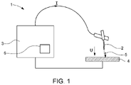
- FIG. 1 a schematic block diagram of a device for welding by means of a non-consumable electrode
- FIG. 2 the temporal waveforms of the welding voltage, the welding current and the power in the arc during normal operation of a device for welding by means of a non-consumable electrode;
- FIG. 3 the temporal waveforms of the welding voltage, the welding current and the power in the arc at the onset of a polarity reversal according to the invention to the negative polarity;
- FIG. 4 the temporal waveforms of the welding voltage, the welding current and the power in the arc at the onset of a polarity reversal according to the invention to the positive polarity;
- FIG. 5 a flowchart illustrating the method according to the invention for welding with a non-consumable electrode.
- FIG. 1 shows a schematic block diagram of a device 1 for welding by means of a non-consumable electrode 2 , in particular a device 1 for TIG (tungsten inert-gas) welding with a tungsten electrode.
- a current source 3 is connected to both the non-consumable electrode 2 and the workpiece 4 made of electrically conductive material.
- the current source 3 applies a welding current I that alternates in polarity with a welding frequency f s between the non-consumable electrode 2 and the workpiece 4 . This causes an arc 5 between the end of the non-consumable electrode 2 and the workpiece 4 to be ignited both in the positive polarity + phase and in the negative polarity ⁇ phase.
- a control device 6 which is usually located in the current source 3 , is used to control the timing sequences and control the respective values of the welding current I and the welding voltage U.
- the control device 6 is designed to measure the welding voltage U between the non-consumable electrode 2 and the workpiece 4 and to measure the welding current I after the change in polarity.
- FIG. 2 shows the temporal waveforms of the welding voltage U, the welding current I, and the power P in the arc during normal operation of a device 1 for welding by means of a non-consumable electrode 2 .
- the welding current I is applied with negative polarity ⁇ with a specific negative welding current.
- the polarity is changed to the positive polarity +.
- the time t p of the positive polarity + has elapsed, the polarity is changed again.
- the times t n of the negative polarity ⁇ and the times t p of the positive polarity are essentially equal in length.
- the resulting welding voltage U as a function of the time t is shown in the second diagram.
- the power P in the arc 5 is shown as a function of the time t.
- voltage threshold values U S ⁇ and U S+ and current threshold values I S ⁇ and I S+ are defined for the negative polarity ⁇ and the positive polarity +, with which the measured values of the welding voltage U and the welding current I are compared, as conditions on whether a polarity reversal should take place.
- a power threshold value P S is also introduced, with which the power P in the arc 5 , either measured or determined from the welding voltage U and the welding current I, is compared as a further condition on reversing the polarity.
- FIG. 2 shows the case in which in either case or with either polarity a reignition of the arc 5 occurs and thus no polarity reversal is necessary, but the polarity is always changed to the next polarity at the specified times.
- FIG. 3 shows the temporal waveforms of the welding voltage U, the welding current I and the power P in the arc at the onset of a polarity reversal according to the invention to the negative polarity ⁇ .
- the preset duration ⁇ t is allowed to elapse and the conditions U>U S+ 1.
- the polarity is changed back to the previous polarity, in the example shown, the negative polarity ⁇ .
- the polarity is changed to the next polarity again as normal. If it has not been possible to break open the oxide layer, then very long phases of the negative polarity ⁇ can result.
- FIG. 4 shows the temporal waveforms of the welding voltage U, the welding current I, and the power P in the arc at the onset of a polarity reversal according to the invention to the positive polarity +.
- the preset duration ⁇ t is allowed to elapse when reversing the polarity from positive polarity + to negative polarity ⁇ and the conditions U>U S ⁇ 1.
- the polarity is then changed back to the previous polarity, in the example shown, the positive polarity +.
- the first polarity change from positive polarity + to negative polarity ⁇ the polarity of the welding current I is changed back again to the positive polarity +.
- the arc is finally successfully re-ignited during the positive polarity +. Therefore, the polarity is then changed to the next polarity again as normal. If no oxide layer is formed, this can also result in long phases of positive polarity.
- FIG. 5 shows a flowchart to illustrate the method according to the invention for welding with a non-consumable electrode.
- the method for welding with a non-consumable electrode is started.
- a welding current I with negative polarity ⁇ is applied (block 101 ), whereupon the preset duration ⁇ t is allowed to elapse (block 102 ) before the measured values of the welding current I are compared with the preset current threshold value I S ⁇ (block 103 ). If the welding current I is less than this preset current threshold value I S ⁇ , the polarity is changed back to the positive polarity + by jumping to block 107 .
- the welding voltage U is compared with the preset voltage threshold value U S ⁇ . If the welding voltage U is greater than this preset voltage threshold U S ⁇ , the polarity is changed back to the positive polarity + by jumping to block 107 . If the welding voltage U is less than or equal to the preset voltage threshold value U S ⁇ , processing continues with query 105 .
- the power P is determined from the welding voltage U and the welding current I and compared with the preset power threshold value P S .
- the polarity is changed back to the positive polarity + by jumping to block 107 . If the power P is greater than or equal to the preset power threshold value P S , the time t n of the negative polarity ⁇ is allowed to elapse (block 106 ) and then the polarity is changed to the positive polarity + (block 107 ).
- the preset duration ⁇ t (which can theoretically differ from the preset duration ⁇ t when changing to the negative polarity ⁇ according to query 102 ) is allowed to elapse (block 108 ) before the measured values of the welding current I are compared with the preset current threshold value I S+ (block 109 ). If the welding current I is less than this preset current threshold value I S+ , the polarity is changed back to the negative polarity ⁇ by jumping to block 101 . If the welding current I is greater than or equal to the preset current threshold value I S+ , processing continues with query 110 . Here, the welding voltage U is compared with the preset voltage threshold value U S+ .
- the polarity is changed back to the negative polarity ⁇ by jumping to block 101 . If the welding voltage U is less than or equal to the preset voltage threshold value U S+ , processing continues with query 111 . Here the power P is compared with the preset power threshold value P S . If the power P is less than this preset power threshold value P S , the polarity is changed back to the negative polarity ⁇ by jumping to block 101 .
- the time t p of the negative polarity ⁇ is allowed to elapse (block 112 ) and then processing proceeds to the query to determine whether the method should be continued (block 113 ). If appropriate, the polarity is changed to the negative polarity ⁇ by returning to block 101 . If the method is to be terminated according to query 113 , the sequence is terminated (block 114 ).
- the flowchart according to FIG. 5 is intended to illustrate a variant of the method according to the invention.
- the comparisons of the measured values with the threshold values can be carried out in any order.
- the flow diagram illustrated shows the comparisons of the measured values with the threshold values in the form of logical “Or” operations.
- Other operations for the comparisons according to the blocks 103 , 104 , 105 or 109 , 110 , 111 in the form of logical “And” or “And/Or” operations would also be possible.
Landscapes
- Engineering & Computer Science (AREA)
- Physics & Mathematics (AREA)
- Plasma & Fusion (AREA)
- Mechanical Engineering (AREA)
- Theoretical Computer Science (AREA)
- Arc Welding Control (AREA)
- Arc Welding In General (AREA)
Abstract
Description
U>
I<I S+ 2.
P<
U>
I<I S− 2.
P<
Claims (9)
Applications Claiming Priority (4)
| Application Number | Priority Date | Filing Date | Title |
|---|---|---|---|
| EP19210533.6 | 2019-11-21 | ||
| EP19210533 | 2019-11-21 | ||
| EP19210533.6A EP3825051A1 (en) | 2019-11-21 | 2019-11-21 | Method and device for welding with a non-consumable electrode |
| PCT/EP2020/082832 WO2021099541A1 (en) | 2019-11-21 | 2020-11-20 | Method and device for welding by means of a non-consumable electrode |
Publications (2)
| Publication Number | Publication Date |
|---|---|
| US20220097160A1 US20220097160A1 (en) | 2022-03-31 |
| US11504792B2 true US11504792B2 (en) | 2022-11-22 |
Family
ID=68653319
Family Applications (1)
| Application Number | Title | Priority Date | Filing Date |
|---|---|---|---|
| US17/429,733 Active 2040-11-24 US11504792B2 (en) | 2019-11-21 | 2020-11-20 | Method and device for welding by means of a non-consumable electrode |
Country Status (4)
| Country | Link |
|---|---|
| US (1) | US11504792B2 (en) |
| EP (2) | EP3825051A1 (en) |
| JP (1) | JP7145344B2 (en) |
| WO (1) | WO2021099541A1 (en) |
Citations (7)
| Publication number | Priority date | Publication date | Assignee | Title |
|---|---|---|---|---|
| EP0586325B1 (en) | 1992-08-28 | 1997-06-04 | Svejsemaskinefabrikken Migatronic A/S | Method and apparatus for TIG welding |
| JP2005193299A (en) | 2003-12-15 | 2005-07-21 | Lincoln Global Inc | Electric arc welding system |
| JP2012000632A (en) | 2010-06-16 | 2012-01-05 | Daihen Corp | Method for controlling feed of arc welding accompanying short circuit |
| US20140263242A1 (en) | 2013-03-14 | 2014-09-18 | Lincoln Global, Inc. | Apparatus and method for welding with ac waveform |
| EP2431119B1 (en) | 2010-02-23 | 2016-08-17 | Panasonic Intellectual Property Management Co., Ltd. | Alternating-current welding method and alternating-current welding device |
| JP2019025503A (en) | 2017-07-27 | 2019-02-21 | 株式会社ダイヘン | Welding power supply |
| JP2019058926A (en) | 2017-09-26 | 2019-04-18 | 株式会社ダイヘン | AC non-consumable electrode arc welding control method |
-
2019
- 2019-11-21 EP EP19210533.6A patent/EP3825051A1/en not_active Withdrawn
-
2020
- 2020-11-20 WO PCT/EP2020/082832 patent/WO2021099541A1/en not_active Ceased
- 2020-11-20 EP EP20807443.5A patent/EP3906132B1/en active Active
- 2020-11-20 US US17/429,733 patent/US11504792B2/en active Active
- 2020-11-20 JP JP2021556869A patent/JP7145344B2/en active Active
Patent Citations (9)
| Publication number | Priority date | Publication date | Assignee | Title |
|---|---|---|---|---|
| EP0586325B1 (en) | 1992-08-28 | 1997-06-04 | Svejsemaskinefabrikken Migatronic A/S | Method and apparatus for TIG welding |
| JP2005193299A (en) | 2003-12-15 | 2005-07-21 | Lincoln Global Inc | Electric arc welding system |
| US7091446B2 (en) | 2003-12-15 | 2006-08-15 | Lincoln Global, Inc. | Electric arc welding system |
| EP2431119B1 (en) | 2010-02-23 | 2016-08-17 | Panasonic Intellectual Property Management Co., Ltd. | Alternating-current welding method and alternating-current welding device |
| JP2012000632A (en) | 2010-06-16 | 2012-01-05 | Daihen Corp | Method for controlling feed of arc welding accompanying short circuit |
| US20140263242A1 (en) | 2013-03-14 | 2014-09-18 | Lincoln Global, Inc. | Apparatus and method for welding with ac waveform |
| JP3204946U (en) | 2013-03-14 | 2016-06-30 | リンカーン グローバル,インコーポレイテッド | Apparatus and method for welding using AC waveform |
| JP2019025503A (en) | 2017-07-27 | 2019-02-21 | 株式会社ダイヘン | Welding power supply |
| JP2019058926A (en) | 2017-09-26 | 2019-04-18 | 株式会社ダイヘン | AC non-consumable electrode arc welding control method |
Non-Patent Citations (3)
| Title |
|---|
| European Search Report in EP 19210533.6-1016, dated Jun. 19, 2020, with English translation of relevant parts. |
| International Search Report in PCT/EP2020/082832, dated Mar. 15, 2021. |
| Japanese Office Action in Japanese Application No. 2021-556869 with English Office Action Summary dated Jul. 12, 2022. |
Also Published As
| Publication number | Publication date |
|---|---|
| US20220097160A1 (en) | 2022-03-31 |
| JP2022531540A (en) | 2022-07-07 |
| EP3825051A1 (en) | 2021-05-26 |
| EP3906132A1 (en) | 2021-11-10 |
| EP3906132B1 (en) | 2022-06-29 |
| JP7145344B2 (en) | 2022-09-30 |
| WO2021099541A1 (en) | 2021-05-27 |
Similar Documents
| Publication | Publication Date | Title |
|---|---|---|
| CN108356390B (en) | Apparatus and method for welding with AC waveforms | |
| US8937267B2 (en) | Method and system to increase heat input to a weld during a short-circuit arc welding process | |
| US20050040144A1 (en) | Control of plasma transitions in sputter processing systems | |
| US6075224A (en) | Method of and apparatus for initiating a welding arc | |
| JP2001150138A (en) | Method for controlling ac pulse arc welding and welding power source device | |
| US3818177A (en) | Arc welding | |
| CN1819887B (en) | Arc welding control method and arc welding machine | |
| EP2431119B1 (en) | Alternating-current welding method and alternating-current welding device | |
| JP2016147312A (en) | Method and system to increase heat input to weld during short-circuit arc welding process | |
| JP2018118316A (en) | Apparatus and method for welding with ac waveform | |
| JP3203123U (en) | Inductive discharge arc re-ignition and stabilization circuit | |
| US11504792B2 (en) | Method and device for welding by means of a non-consumable electrode | |
| EP2197619B1 (en) | Method of short-time stud joining with several advances of the first workpiece in direction to the second workpiece for creating an arc | |
| JPS649114B2 (en) | ||
| EP0667205A1 (en) | Synchronized pulse arc starter and stabilizer for arc welding | |
| JPH01299768A (en) | Consumable electrode type rectangular wave ac arc welding method | |
| US6566625B1 (en) | Welding apparatus and method | |
| CN116075383B (en) | Method and welding device for contactless ignition of an arc | |
| JP4776868B2 (en) | Method used in gas shielded metal arc welding | |
| CN111112796A (en) | Time-based short circuit response | |
| JP2019005766A (en) | Non-consumable electrode pulse arc welding control method | |
| JP4341527B2 (en) | Consumable electrode arc welding method | |
| JPH09108836A (en) | Control method of consumable electrode type AC arc welding machine | |
| SU1006126A1 (en) | Method of arc-welding by non-consumable electrode | |
| SU1143544A1 (en) | Arc welding arrangement |
Legal Events
| Date | Code | Title | Description |
|---|---|---|---|
| AS | Assignment |
Owner name: FRONIUS INTERNATIONAL GMBH, AUSTRIA Free format text: ASSIGNMENT OF ASSIGNORS INTEREST;ASSIGNORS:LATTNER, PETER;ARTELSMAIR, JOSEF;REEL/FRAME:057144/0876 Effective date: 20210810 |
|
| FEPP | Fee payment procedure |
Free format text: ENTITY STATUS SET TO UNDISCOUNTED (ORIGINAL EVENT CODE: BIG.); ENTITY STATUS OF PATENT OWNER: LARGE ENTITY |
|
| STPP | Information on status: patent application and granting procedure in general |
Free format text: DOCKETED NEW CASE - READY FOR EXAMINATION |
|
| STPP | Information on status: patent application and granting procedure in general |
Free format text: NOTICE OF ALLOWANCE MAILED -- APPLICATION RECEIVED IN OFFICE OF PUBLICATIONS |
|
| STCF | Information on status: patent grant |
Free format text: PATENTED CASE |