EP0585607A1 - Espresso coffee machine - Google Patents
Espresso coffee machine Download PDFInfo
- Publication number
- EP0585607A1 EP0585607A1 EP93112123A EP93112123A EP0585607A1 EP 0585607 A1 EP0585607 A1 EP 0585607A1 EP 93112123 A EP93112123 A EP 93112123A EP 93112123 A EP93112123 A EP 93112123A EP 0585607 A1 EP0585607 A1 EP 0585607A1
- Authority
- EP
- European Patent Office
- Prior art keywords
- machine according
- espresso machine
- storage plate
- screw drive
- pot
- Prior art date
- Legal status (The legal status is an assumption and is not a legal conclusion. Google has not performed a legal analysis and makes no representation as to the accuracy of the status listed.)
- Granted
Links
Images
Classifications
-
- A—HUMAN NECESSITIES
- A47—FURNITURE; DOMESTIC ARTICLES OR APPLIANCES; COFFEE MILLS; SPICE MILLS; SUCTION CLEANERS IN GENERAL
- A47J—KITCHEN EQUIPMENT; COFFEE MILLS; SPICE MILLS; APPARATUS FOR MAKING BEVERAGES
- A47J31/00—Apparatus for making beverages
- A47J31/44—Parts or details or accessories of beverage-making apparatus
- A47J31/4482—Details allowing to adapt the beverage-making apparatus to the size of the brewing vessel or the beverage container, e.g. with adjustable support for the beverage container or adjustable hot water outlet
Definitions
- the invention relates to an espresso machine with an outlet opening for the prepared espresso beverage and a storage plate arranged at a distance below the outlet opening, which is supported by a device base and on which a receptacle receiving the beverage can be placed, a receiving space for excess liquid being present below the storage plate and wherein a mechanical height adjustment device is provided between the storage plate and the device base, which enables a change in the distance.
- a beverage preparation machine of the type described at the outset is already known from DE-A1-29 22 022, in which the drip tray arranged on the base of the appliance with its storage plate has a mechanical height adjustment device is adjustable in height with respect to the outlet opening.
- the height adjustment device consists, among other things, of a guide sleeve attached to the side of the appliance base, which can be pushed along on a column arranged in the longitudinal direction of the brewing beverage machine and thus adjustable in height with respect to the outlet opening.
- the column has an oval cross-section, which can be rotated by means of a handle relative to the bore of the column in order to prevent jamming between the column and the sleeve and thus to achieve a locking between the two parts.
- the handling is less advantageous, since both an axial and a subsequent twisting movement must be carried out on the handle when manually adjusting the height. This easily leads to the fact that a vessel located on the storage plate can easily fall down, since bucking movements are almost inevitable in such an adjustment process.
- Another disadvantage is that if, for example, drinks flow through the storage plate into the recess formed in the table, it is difficult to clean.
- the object of the invention is therefore to provide an espresso machine in which the handling of the height adjustment device is improved and simplified, in which a variety of different positions can be achieved with the height adjustment device in spite of the simple design, and in which simple cleaning of the collecting space is possible.
- the support plate is supported on the device base by means of an intervening collecting tray which forms the collecting space for the excess liquid and which is detachably connected to the device base, that the storage plate is also detachably connected to the collecting tray, that the height adjustment device works on the basis of a screw drive and that the screw drive acts either between the device base and the collecting tray or between the collecting tray and the storage plate, in the first case the device base and collecting tray and in the second case the collecting tray and storage plate are relatively movable with respect to one another.
- the distance between the outlet opening and the storage plate can be varied in many positions with simple means and the height of the respective collecting vessel can thus be optimally adapted.
- the distance between the storage plate and the outlet openings can be adjusted so that the edge of the collecting container is located slightly below the outlet openings. If necessary, it is even possible to adjust the distance so that the pouring openings even protrude into the collecting container.
- the annoying alignment processes of the collecting container under the outlet openings can finally be considerably improved and the drink gets completely into the collecting container without parts flowing sideways past the collecting container.
- the use of larger collecting containers is no longer a problem according to the invention, since the distance X is increased by lowering the storage plate until the highest vessel to be used for the espresso machine can also be stored.
- the screw drive should therefore be designed in such a way that its height can be adjusted so that the espresso cups can be placed under the outlet openings.
- the screw drive according to the invention between the collecting tray and the storage surface results in a particularly simple handling, since when the collecting tray is rotated, the storage surface is adjusted in height relative to the collecting tray or with respect to the device base, the screw drive being automatically locked in different rotational positions and thus a tight fit of the Storage space is reached. Jerky movements on the storage surface are avoided since a rotary movement, that is to say in only one direction of movement, can be carried out easily and evenly by the hand of an operator. Furthermore, a screw drive between the storage surface and the drip tray can be produced easily and inexpensively, since, in addition to the storage plate, the components in question can be molded from plastic, so that such screw drives can be easily molded when the components are removed without any significant expense.
- this arrangement can be cleaned particularly easily by hand and then reassembled in such a way that a height-adjustable storage tray with a drip tray underneath is created.
- a particularly user-friendly arrangement results if the screw drive is formed between the collecting tray and the storage surface.
- the screw drive can be particularly easily integrated into the components that can be removed from the device be what simplifies manufacturing. It is possible that the storage plate rotates relative to the drip tray when the screw drive is actuated.
- the collecting pan rotates relative to the storage plate when the screw drive is actuated.
- the screw drive is arranged between the device base and the drip tray. It is then necessary that when the screw drive is actuated, the drip pan rotates relative to the appliance base, it being better if the appliance base forms a part with the housing of the espresso machine.
- the storage plate should also be non-rotatable but height-adjustable.
- the collecting tray can be locked in several angular positions by a locking mechanism.
- the storage plate can be brought to different heights by simple rotation of the collecting tray and fixed there.
- the distance between the storage plate and the outlet opening can be optimally adapted to the respective vessel height using a handle which, for example, consists of an annular surface protruding radially on the storage plate.
- the locking mechanism automatically ensures the locking in the respective position, so that no additional actuation is required for this.
- the storage plate with the drip tray is prevented from rotating relative to the device base by a vertical guide. As a result, when the drip tray is rotated, the storage plate moves away from the drip tray and the device base. This also applies analogously to a torsion-proof drip tray.
- the bottom of the drip tray has projections or recesses on its underside, which are formed by complementarily shaped recesses or projections on the device base.
- Such a locking mechanism has the advantage that it is held in its snap-in position by the weight of the drip tray, storage plate and additionally the vessel located on it. Additional holding means are not necessary. The locking force automatically adapts to the respective load condition.
- the screw drive advantageously has a plurality of screw threads.
- the ease of use is increased and an easier introduction to the threads is achieved.
- the removability of the storage surface and the quick assembly of the latter in relation to the collecting tray are achieved.
- the drip tray has a cylindrical pot and that the storage plate is provided on its underside with a cylindrical attachment which is longitudinally displaceable and is mounted in the pot of the drip tray via the screw drive, screw surfaces being provided on the pot or on the attachment that form the screw drive with counter surfaces on the base or on the pot.
- a screw drive is formed in a simple manner with the aid of the collecting tray, which is easy to manufacture and enables the storage plate to be removed from the collecting tray.
- the shelf can be easily centered over its attachment in the pot.
- the attachment of the storage plate is designed as a cylindrical collar and that the screw surfaces are formed by cutouts in the collar.
- the screw surfaces can be formed by inwardly projecting steps in the wall of the pot. In both ways, the screw surfaces can be produced with simple molding tools, since the parts of the molding tools only have to be moved axially to one another. In addition, the location of the screw surfaces allows the storage plate to be removed without the need to rotate the collecting tray.
- the counter surfaces through the ends of ribs parallel to the screw axis on the Inner wall of the pot or the outer wall of the approach are formed. This also contributes to the ease of manufacture.
- the screw drive results from the fact that the three screw surfaces are each formed by two inwardly projecting and parallel wall surfaces, each forming a thread groove, in which protruding pins on the outer surface of the collar engage as counter surfaces. This ensures that the shelf is in firm and centered engagement with the drip tray via the screw drive, so that the shelf cannot easily be lifted out of the drip tray.
- each upper wall surface is formed by a rib formed on the inner wall of the pot. Due to the ribs formed on the inner wall and the recesses on the pot, the drip tray can be produced particularly easily by injection molding, without the need for expensive inserts.
- the threaded grooves are open at their ends near the bottom and at their other ends , upper ends are closed by a wall.
- a central telescopic guide consisting of a bearing pin and guide sleeve of small diameter can be provided according to a further proposal of the invention, which is connected on the one hand to the storage tray and on the other hand to the drip tray.
- the vertical guide consists of a radial extension formed on the storage plate, which is supported in the tangential direction on the housing of the device. This ensures in a simple form that when the drip tray rotates, the storage plate shifts in height, the latter then sliding up and down on the housing.
- the device base 1 of the hot beverage maker has a cylindrical, upwardly open receiving space 2, which is formed by a recess arranged in the device base 1.
- a cylindrical, upwardly open receiving space 2 which is formed by a recess arranged in the device base 1.
- three projections 4 with a spherical surface are arranged at a uniform distance from one another and from the cylinder axis.
- the receiving space 2 there is a cylindrical pot 5 of a collecting tray 6.
- the outer diameter of the pot 5 is only smaller than the inside diameter of the receiving space 2 by the required play, so that the collecting tray 6 is easily rotatable in the receiving space 2.
- the edge of the pot 5 is designed as an annular disk 7, which extends beyond the outer edge of the device base 1 and is inclined in a funnel-like manner towards the pot 5.
- the bottom 8 of the pot 5 has on its underside recesses 9 in the form of spherical caps, which are formed by the bulges of the bottom 8.
- the number of recesses 9 is at least three or a multiple thereof and in each case three recesses 9 are positioned in the same way as the projections 4.
- the recesses 9 form a locking mechanism with the projections 4, in that the three projections 4 each snap into three recesses 9 . If there are three recesses 9, there are three angular positions at a distance of 120 °, in which the drip tray 6 can be held by the locking mechanism.
- the drip tray 6 carries a shelf 12 with drain slots 13.
- the shelf 12 has on its underside a cylindrical collar 14 which engages in the pot 5 and is guided on the inner wall of the pot 5.
- the collar 14 has three cutouts 15, through which three comparatively steep screw surfaces 16 are formed.
- the screw surfaces 16 cooperate with the counter surfaces 11 of the ribs 10, whereby a screw drive is formed which moves the storage plate 12 in the direction of the cylinder axis with respect to the collecting bowl 6 when the collecting bowl 6 rotates with respect to the storage plate 12.
- equivalent screw drives are also possible.
- the storage plate 12 is prevented from rotating relative to the housing 18 of the hot beverage maker by a projection 17 projecting radially beyond the disk 7 by the extension 17 engaging in a vertical guide groove 19 in the housing 18.
- the shelf 12 is shown in its lowest position, where it rests on the ribs 10 with the collar 14.
- the drip tray 6 is rotated clockwise, whereby it can be gripped on the outer edge of the disk 7.
- the ribs 10 move against the screw surfaces 16 and the counter surfaces 11 slide along the screw surfaces 16 and thereby cause the storage plate 12 to be lifted when it slides over its shoulder 17 in the guide groove 19 upwards and is thereby rotationally fixed is held on the housing 18.
- the recesses 9 are lifted from the projections 4 and the base 8 slides over the projections 4 until after an angle of rotation of 120 °, for example, the recesses 9 snap onto the projections 4 again.
- the maximum lifting height of the storage plate 12 is determined by the height of the screw surface 16.
- the holding of the storage plate 12 in a raised position is ensured solely by the engagement of the projections 4 in the recesses 9, since the pitch of the screw surfaces 16 lies outside the self-locking area.
- the projections 4 are held in engagement by the weight of the drip tray 6 and the storage plate 12.
- the engagement is correspondingly increased by its weight.
- the storage plate 12 can be lowered again.
- the storage plate 12 is sufficiently guided on its cylindrical surface of the collar 14 in the cylindrical recess 2, so that even when the storage plate 12 is fully extended, it does not tilt.
- Separate guide devices (not shown) in the form of, for example, a link guide can also be used for this purpose.
- the basic structure and the mode of operation of the variant shown in FIG. 2 correspond to the exemplary embodiment according to FIG. 1. However, the design of the locking mechanism and the screw drive is different.
- spherical cap-shaped recesses 20 are provided at a uniform circumferential distance from one another, and the bottom 8 of the collecting tray 6 has correspondingly positioned spherical projections 21 on its underside which snap into the recesses 20.
- the screw surfaces 16 of the screw drive are formed by inwardly projecting steps 22 in the wall of the pot 5 and the collar 14 of the storage plate 12 has on its outside ribs 23 which have the counter surfaces 11 at their lower ends. Since the collar 14 is not interrupted by cutouts 15, its wall thickness can be smaller.
- the drip tray 6 has a cylindrical bearing journal 24 coaxial with the cylinder axis, which engages in a guide sleeve 25 arranged on the underside of the storage plate 12.
- the bearing pin 24 and the guide sleeve 25 have a diameter which is favorable in relation to the guide length and thereby ensure that the storage plate 12 is guided without jamming.
- a collecting container 27 in the form of an espresso cup is placed on the storage plate 12 and its edge 28 is arranged below the two outlet openings 26 arranged next to one another.
- the outlet openings 26 are part of a sieve basket support 29, in which a sieve 31 is inserted on the bottom 30, on which the espresso flour 32 rests.
- the strainer basket support 29 is inserted into a strainer basket holding device, not shown in the drawing, of an espresso machine, so that the position shown in the drawing results. No further details of an espresso machine will be given here, since it is already generally known, as mentioned at the beginning.
- the ribs 23 move up and down with their counter surfaces 11 on the screw surfaces 16, so that the distance X decreases or increases.
- the edge 28 of the espresso cup 27 can be brought sufficiently close to the outlet openings 26, so that heat losses and in addition splashing or running are avoided during pouring.
- the device base 1 with its receiving space 2 has been omitted for the sake of simplicity.
- the storage surface 12 is partially moved out of the collecting tray 6 and the screw surfaces 16 formed on the inner wall of the receiving space 2 of the collecting tray 6 each consist of two inwardly projecting and parallel wall surfaces 34, 35, between which a threaded groove 37 is formed that form part of a non-self-locking thread.
- the thread starts 40 are kept open by the thread grooves 37, so that the pins 41 formed on the outer surface of the cylindrical collar 14 with their upward and downward-facing counter surfaces 11 can be introduced into the thread grooves 37 by rotating the collecting shell 6 counterclockwise, to then move the storage plate 12 upwards in height when the drip tray 6 rotates further, if this is secured against rotation by a guide groove or a pin 19.
- the base 8 of the drip tray 6 is supported by the spherical projections 21 in also spherical recesses, as shown in FIG. 1, formed on the base of the device base 1.
- the upper free ends of the threaded grooves 37 are delimited to the outside by a wall 39, so that when the storage plate 12 has been screwed out all the way up, the pins 41 abut the walls 39, as a result of which the storage plate 12 can no longer be rotated.
- the lower wall surfaces 35 are formed in that the sections 36 formed below the wall surfaces 35 are drawn in towards the center line 42 and run concentrically to this or to the wall surface of the pot 5.
- the indented depressions 36 form the shape of a right-angled triangle, the hypotenuse representing the side that forms the lower wall surface 35.
- the recesses 43 in which the upper wall surfaces 34 engage, adjoin the pins 41. Approximately the same dimension in longitudinal section as the pins 41 adjoin the recesses 43 upward webs 38 which for the purpose of guiding the storage plate 12 abut the inner wall of the pot 5 of the drip pan 6, which, however, is not the case in FIG. 3 is shown, since there must always be little play between these areas to prevent jamming.
- the pins 41 When inserting the storage plate 12 over the collar 14 into the receiving space 2, the pins 41 must be arranged in the region which results between the line 44 and the thread entry 40, ie outside the vertical projection of the threads 16.
- the spherical projections 21 form Locking elements, as described in Fig. 1, so that it will not be discussed at this point.
Abstract
Description
Die Erfindung betrifft eine Espressomaschine mit einer Austrittsöffnung für das zubereitete Espressogetränk und einer unter der Austrittsöffnung im Abstand angeordneten Abstellplatte, die durch einen Gerätefuß abgestützt wird und auf der ein das Getränk aufnehmender Auffangbehälter abstellbar ist, wobei unterhalb der Abstellplatte ein Aufnahmeraum für überschüssige Flüssigkeit vorhanden ist und wobei zwischen der Abstellplatte und dem Gerätefuß eine mechanische Höhenverstelleinrichtung vorgesehen ist, die eine Veränderung des Abstandes ermöglicht.The invention relates to an espresso machine with an outlet opening for the prepared espresso beverage and a storage plate arranged at a distance below the outlet opening, which is supported by a device base and on which a receptacle receiving the beverage can be placed, a receiving space for excess liquid being present below the storage plate and wherein a mechanical height adjustment device is provided between the storage plate and the device base, which enables a change in the distance.
Aus der Firmendruckschrift "Braun Programmübersicht 1992" vom Januar 1992, Seite 49, ist bereits eine Espressomaschine bekannt, bei der der Gerätefuß eine Ausnehmung aufweist, in die die mittige Einsenkung einer Auffangschale einsetzbar ist. Die Auffangschale wird durch eine Abstellplatte abgedeckt. Sowohl die Auffangschale als auch die Abstellplatte sind abnehmbar und daher leicht zu reinigen. Auf die Abstellplatte können zur Aufnahme des zubereiteten Espressos sowohl ein oder zwei Tassen als auch eine Kanne plaziert werden. Bei der unterschiedlichen Höhe der Auffanggefäße muß der Abstand zwischen Austrittsöffnung und Abstellplatte an die Höhe des größten Gefäßes angepaßt sein. Dies hat zur Folge, daß bei niedriger Gefäßhöhe der Abstand zwischen der Austrittsöffnung und dem Gefäß so groß ist, daß der Espresso über den Rand des Gefäßes hinaus spritzen oder gar fließen kann. Zudem kann es zu einer unerwünscht raschen Abkühlung des Getränks kommen.An espresso machine is already known from the company publication "Braun Program Overview 1992" from January 1992, page 49, in which the base of the device has a recess into which the central depression of a drip tray can be inserted. The drip tray is covered by a shelf. Both the drip tray and the shelf are removable and therefore easy to clean. Both one or two cups and a jug can be placed on the shelf to hold the prepared espresso. Given the different heights of the collecting vessels, the distance between the outlet opening and the storage plate must be adapted to the height of the largest vessel. As a result, the distance between the outlet opening and the vessel is so large that the espresso can splash or even flow over the edge of the vessel at a low vessel height. In addition, the drink can cool down undesirably quickly.
Um die oben erwähnten Nachteile zu vermeiden, ist aus der DE-A1-29 22 022 bereits eine Getränkezubereitungsmaschine der eingangs beschriebenen Art bekannt, bei der die am Gerätefuß angeordnete Auffangschale mit seiner Abstellplatte über eine mechanische Höhenverstelleinrichtung gegenüber der Austrittsöffnung höhenverstellbar ist. Dabei besteht die Höhenverstelleinrichtung unter anderem aus einer am Gerätefuß seitlich angebrachten Führungshülse, die auf einer in Längsrichtung der Brühgetränkemaschine angeordneten Säule entlangschiebbar und somit gegenüber der Austrittsöffnung höhenverstellbar ist. Um die Hülse und somit den Gerätefuß auf jeder beliebigen Höhe arretieren zu können, weist die Säule einen ovalen Querschnitt auf, die durch ihre Drehung über eine Handhabe gegenüber der Bohrung der Säule verdreht werden kann, um zwischen der Säule und der Hülse eine Verklemmung und somit eine Arretierung zwischen beiden Teilen zu erzielen. Abgesehen von dem verhältnismäßig aufwendigen Aufbau der Höhenverstelleinrichtung ist die Handhabung weniger vorteilhaft, da bei einer Höhenverstellung von Hand sowohl eine axiale wie eine sich anschließende Verdrehbewegung an der Handhabe ausgeführt werden muß. Dies führt leicht dazu, daß ein auf der Abstellplatte sich befindendes Gefäß leicht herunterfallen kann, da bei einem derartigen Verstellvorgang Ruckelbewegungen nahezu unvermeidbar sind. Ein weiterer Nachteil besteht darin, daß, wenn beispielsweise Getränke über die Abstellplatte in die im Stelltisch ausgebildete Ausnehmung fließen, diese nur schwer reinigbar ist.In order to avoid the disadvantages mentioned above, a beverage preparation machine of the type described at the outset is already known from DE-A1-29 22 022, in which the drip tray arranged on the base of the appliance with its storage plate has a mechanical height adjustment device is adjustable in height with respect to the outlet opening. The height adjustment device consists, among other things, of a guide sleeve attached to the side of the appliance base, which can be pushed along on a column arranged in the longitudinal direction of the brewing beverage machine and thus adjustable in height with respect to the outlet opening. In order to be able to lock the sleeve and thus the device foot at any height, the column has an oval cross-section, which can be rotated by means of a handle relative to the bore of the column in order to prevent jamming between the column and the sleeve and thus to achieve a locking between the two parts. Apart from the relatively complex structure of the height adjustment device, the handling is less advantageous, since both an axial and a subsequent twisting movement must be carried out on the handle when manually adjusting the height. This easily leads to the fact that a vessel located on the storage plate can easily fall down, since bucking movements are almost inevitable in such an adjustment process. Another disadvantage is that if, for example, drinks flow through the storage plate into the recess formed in the table, it is difficult to clean.
Weiterhin ist aus dem DE-U1-79 15 161 eine weitere Höhenverstelleinrichtung für eine Espressomaschine bekannt, bei der die Abstellplatte, unabhängig vom Gerätefuß, lediglich nur in zwei verschiedenen Höhenlagen über am Gerät ausgebildete Schlitze eingesetzt werden kann. Durch die Trennung der Abstellplatte gegenüber dem Gerätefuß ergibt sich der Nachteil, daß am Gefäß vorbeifließendes Getränk auf den Gerätefuß trifft, was zwangsweise zu einem Verspritzen der Espressomaschine, der Abstellfläche und eventuell in der Nähe der Espressomaschine stehender anderer Küchengeräte durch das Getränk führt.Furthermore, from DE-U1-79 15 161 a further height adjustment device for an espresso machine is known, in which the storage plate, regardless of the device base, can only be used at two different heights via slots formed on the device. By separating the shelf from the appliance base, there is the disadvantage that beverage flowing past the vessel meets the appliance base, which inevitably leads to splashing of the espresso machine, the storage surface and possibly other kitchen appliances standing near the espresso machine through the beverage.
Aufgabe der Erfindung ist es daher, eine Espressomaschine zu schaffen, bei der die Handhabung der Höhenverstelleinrichtung verbessert und vereinfacht wird, bei der mit der Höhenverstelleinrichtung trotz einfacher Ausgestaltung eine Vielzahl von verschiedenen Positionen erreicht werden kann und bei der eine einfache Reinigung des Auffangraumes möglich ist.The object of the invention is therefore to provide an espresso machine in which the handling of the height adjustment device is improved and simplified, in which a variety of different positions can be achieved with the height adjustment device in spite of the simple design, and in which simple cleaning of the collecting space is possible.
Diese Aufgabe wird erfindungsgemäß dadurch gelöst, daß die Abstützung der Abstellplatte auf dem Gerätefuß über eine dazwischen liegendene Auffangschale erfolgt, die den Auffangraum für die überschüssige Flüssigkeit bildet und die mit dem Gerätefuß lösbar verbunden ist, daß auch die Abstellplatte lösbar mit der Auffangschale verbunden ist, daß die Höhenverstelleinrichtung auf der Grundlage eines Schraubentriebs arbeitet und daß der Schraubentrieb entweder zwischen dem Gerätefuß und der Auffangschale oder zwischen der Auffangschale und der Abstellplatte wirkt, wobei im ersten Fall Gerätefuß und Auffangschale und im zweiten Fall Auffangschale und Abstellplatte relativ gegeneinander beweglich sind. Hierdurch kann der Abstand zwischen Austrittsöffnung und Abstellplatte mit einfachen Mitteln in vielen Stellungen variiert und somit der Höhe des jeweiligen Auffanggefäßes optimal angepaßt werden kann. Dabei kann der Abstand der Abstellplatte gegenüber den Austrittsöffnungen so eingestellt werden, daß der Rand des Auffangbehälters geringfügig unterhalb der Austrittsöffnungen angeordnet ist. Bei Bedarf ist es sogar möglich, den Abstand so einzustellen, daß die Ausgießöffnungen sogar in den Auffangbehälter hineinragen.This object is achieved according to the invention in that the support plate is supported on the device base by means of an intervening collecting tray which forms the collecting space for the excess liquid and which is detachably connected to the device base, that the storage plate is also detachably connected to the collecting tray, that the height adjustment device works on the basis of a screw drive and that the screw drive acts either between the device base and the collecting tray or between the collecting tray and the storage plate, in the first case the device base and collecting tray and in the second case the collecting tray and storage plate are relatively movable with respect to one another. As a result, the distance between the outlet opening and the storage plate can be varied in many positions with simple means and the height of the respective collecting vessel can thus be optimally adapted. The distance between the storage plate and the outlet openings can be adjusted so that the edge of the collecting container is located slightly below the outlet openings. If necessary, it is even possible to adjust the distance so that the pouring openings even protrude into the collecting container.
Durch die Erfindung können endlich die stets lästigen Ausrichtvorgänge des Auffangbehälters unter den Austrittsöffnungen erheblich verbessert werden und das Getränk gelangt, ohne daß Anteile seitlich am Auffangbehälter vorbeifließen, vollständig in den Auffangbehälter. Auch die Verwendung von größeren Auffangbehältern stellt nach der Erfindung kein Problem mehr dar, da der Abstand X durch Absenken der Abstellplatte derart vergrößert wird, bis auch das für die Espressomaschine zu verwendende höchste Gefäß unterstellbar ist. Der Schraubentrieb sollte also in seiner Höhenverstellbarkeit so ausgelegt werden, daß die für Espresso üblichen Gefäße unter den Austrittsöffnungen Platz finden.By means of the invention, the annoying alignment processes of the collecting container under the outlet openings can finally be considerably improved and the drink gets completely into the collecting container without parts flowing sideways past the collecting container. The use of larger collecting containers is no longer a problem according to the invention, since the distance X is increased by lowering the storage plate until the highest vessel to be used for the espresso machine can also be stored. The screw drive should therefore be designed in such a way that its height can be adjusted so that the espresso cups can be placed under the outlet openings.
Durch den erfindungsgemäßen Schraubentrieb zwischen der Auffangschale und der Abstellfläche ergibt sich eine besonders einfache Handhabung, da bei Verdrehung der Auffangschale die Abstellfläche gegenüber der Auffangschale bzw. gegenüber dem Gerätefuß höhenverstellt wird, wobei in verschiedenen Drehstellungen der Schraubentrieb selbsttätig arretiert wird und so ein fester Sitz der Abstellfläche erreicht wird. Dabei werden Ruckelbewegungen an der Abstellfläche vermieden, da eine Drehbewegung, also in nur einer Bewegungsrichtung, von der Hand einer Bedienungsperson leicht und gleichmäßig ausführbar ist. Des weiteren ist ein Schraubentrieb zwischen der Abstellfläche und der Auffangschale leicht und kostengünstig herstellbar, da außer der Abstellplatte die in Frage stehenden Bauteile aus Kunststoff geformt sein können, so daß derartige Schraubentriebe leicht beim Ausformen der Bauteile ohne nennenswerten Kostenaufwand mit ausgeformt werden können. Durch den Einsatz einer vom Gerätefuß lösbaren Auffangschale, von der auch die Abstellplatte entfernbar ist, läßt sich diese Anordnung besonders einfach von Hand reinigen und anschließend wieder so zusammensetzen, daß wieder eine höhenverstellbare Abstellplatte mit darunter angeordneter Auffangschale entsteht.The screw drive according to the invention between the collecting tray and the storage surface results in a particularly simple handling, since when the collecting tray is rotated, the storage surface is adjusted in height relative to the collecting tray or with respect to the device base, the screw drive being automatically locked in different rotational positions and thus a tight fit of the Storage space is reached. Jerky movements on the storage surface are avoided since a rotary movement, that is to say in only one direction of movement, can be carried out easily and evenly by the hand of an operator. Furthermore, a screw drive between the storage surface and the drip tray can be produced easily and inexpensively, since, in addition to the storage plate, the components in question can be molded from plastic, so that such screw drives can be easily molded when the components are removed without any significant expense. By using a drip tray that can be detached from the base of the device and from which the storage tray can also be removed, this arrangement can be cleaned particularly easily by hand and then reassembled in such a way that a height-adjustable storage tray with a drip tray underneath is created.
Eine besonders bedienungsfreundliche Anordnung ergibt sich, wenn der Schraubentrieb zwischen der Auffangschale und der Abstellfläche ausgebildet ist. Dabei kann nämlich der Schraubentrieb besonders einfach in die vom Gerät abnehmbaren Bauteile integriert werden, was die Herstellung vereinfacht. Dabei ist es möglich, daß sich bei Betätigung des Schraubentriebs die Abstellplatte gegenüber der Auffangschale verdreht.A particularly user-friendly arrangement results if the screw drive is formed between the collecting tray and the storage surface. The screw drive can be particularly easily integrated into the components that can be removed from the device be what simplifies manufacturing. It is possible that the storage plate rotates relative to the drip tray when the screw drive is actuated.
Vorteilhafter ist es aber, wenn sich bei Betätigung des Schraubentriebs die Auffangschale gegenüber der Abstellplatte verdreht. Hierdurch ergibt sich eine besonders einfache Handhabung, da beim Betätigen des Schraubentriebs sich nicht der auf der Abstellplatte abgestellte Auffangbehälter verdreht, so daß der an dem Auffangbehälter üblicherweise angebrachte Henkel sich nicht von der Bedienungsseite wegdrehen kann. Es ist aber dennoch auch durchaus denkbar, daß der Schraubentrieb zwischen dem Gerätefuß und der Auffangschale angeordnet ist. Dabei ist es dann notwendig, daß sich bei Betätigung des Schraubentriebs die Auffangschale gegenüber dem Gerätefuß verdreht, wobei es dann besser ist, wenn der Gerätefuß ein Teil mit dem Gehäuse der Espressomaschine bildet Bei dieser Variante sollte ebenfalls die Abstellplatte verdrehsicher aber höhenverstellbar sein.However, it is more advantageous if the collecting pan rotates relative to the storage plate when the screw drive is actuated. This results in a particularly simple handling, since when the screw drive is actuated, the collecting container placed on the storage plate does not twist, so that the handle usually attached to the collecting container cannot turn away from the operating side. However, it is also quite conceivable that the screw drive is arranged between the device base and the drip tray. It is then necessary that when the screw drive is actuated, the drip pan rotates relative to the appliance base, it being better if the appliance base forms a part with the housing of the espresso machine. In this variant, the storage plate should also be non-rotatable but height-adjustable.
Wählt man in einer Weiterbildung der Erfindung als Schraubentrieb, gleichgültig ob dieser zwischen der Auffangschale und der Abstellplatte oder zwischen der Auffangschale und dem Gerätefuß angeordnet ist, ein selbsthemmendes Gewinde, so ergibt sich hieraus der Vorteil, daß die Höhenverstelleinrichtung in jeder beliebigen Drehstellung fixiert werden kann, ohne daß zur Fixierung zusätzliche Rastelemente nötig wären. Hierdurch kann also der Rand jedes Auffangbehälters optimal nahe an die Austrittsöffnungen herangeführt werden, indem bei auf der Abstellplatte abgestelltem Auffangbehälter die Höhenverstelleinrichtung so lange verstellt wird, bis der Rand des Auffangbehälters den gewünschten Abstand zu den Austrittsöffnungen aufweist. Wählt man allerdings als Schraubentrieb ein nicht-selbsthemmendes Gewinde, so ergeben sich aufgrund der größeren Steigung des Gewindes bereits bei kleinen Drehwinkeln verhältnismäßig große Höhenverstellungen, wobei dann allerdings Rastelemente nötig werden, die eine Arretierung der Höhenverstelleinrichtung in verschiedenen Positionen bewirken.If you choose a self-locking thread in a further development of the invention as a screw drive, regardless of whether this is arranged between the collecting tray and the storage plate or between the collecting tray and the device base, this results in the advantage that the height adjustment device can be fixed in any rotational position without additional locking elements being required for fixation. As a result, the edge of each collecting container can be brought optimally close to the outlet openings by adjusting the height adjustment device until the edge of the collecting container is at the desired distance from the outlet openings when the collecting container is placed on the storage plate. However, if you choose a non-self-locking thread as the screw drive, the larger pitch of the thread results in relatively large height adjustments even at small angles of rotation, whereby locking elements are then necessary, however lock the height adjustment device in different positions.
In einer bevorzugten Weiterbildung der Erfindung bei der Verwendung eines nicht-selbsthemmenden Gewindes wird vorgeschlagen, daß die Auffangschale durch ein Rastgesperre in mehreren Winkelstellungen arretierbar ist. Hierdurch kann mit einfachen Mitteln die Abstellplatte durch Drehen der Auffangschale in unterschiedliche Höhenlagen gebracht und dort festgestellt werden. Auf diese Weise läßt sich der Abstand der Abstellplatte zur Austrittsöffnung mit einem Handgriff, der beispielsweise aus einer radial an der Abstellplatte herausragenden Ringfläche besteht, an die jeweilige Gefäßhöhe optimal anpassen. Das Rastgesperre sorgt dabei selbsttätig für die Arretierung in der jeweiligen Stellung, so daß es hierzu keiner zusätzlichen Betätigung bedarf.In a preferred development of the invention when using a non-self-locking thread, it is proposed that the collecting tray can be locked in several angular positions by a locking mechanism. As a result, the storage plate can be brought to different heights by simple rotation of the collecting tray and fixed there. In this way, the distance between the storage plate and the outlet opening can be optimally adapted to the respective vessel height using a handle which, for example, consists of an annular surface protruding radially on the storage plate. The locking mechanism automatically ensures the locking in the respective position, so that no additional actuation is required for this.
In einer Weiterbildung der Erfindung ist vorgesehen, daß die Abstellplatte mit der Auffangschale durch eine Vertikalführung an einer Drehung gegenüber dem Gerätefuß gehindert ist. Hierduch entfernt sich bei Drehung der Auffangschale die Abstellplatte gegenüber der Auffangschale und dem Gerätefuß. Sinngemäß gilt dies auch bei verdrehfester Auffangschale.In a further development of the invention it is provided that the storage plate with the drip tray is prevented from rotating relative to the device base by a vertical guide. As a result, when the drip tray is rotated, the storage plate moves away from the drip tray and the device base. This also applies analogously to a torsion-proof drip tray.
Zur Bildung des Rastgesperres kann erfindungsgemäß vorgesehen sein, daß der Boden der Auffangschale auf seiner Unterseite Vorsprünge bzw. Ausnehmungen aufweist, denen am Gerätefuß ausgebildete und komplementär geformte Ausnehmungen bzw. Vorsprünge gegenüberliegen. Ein derartiges Rastgesperre hat den Vorteil, daß es durch das Eigengewicht von Auffangschale, Abstellplatte und zusätzlich dem darauf befindlichen Gefäß in seiner Einrastposition gehalten wird. Weitere Haltemittel sind entbehrlich. Die Sperrkraft paßt sich selbsttätig dem jeweiligen Belastungszustand an.To form the locking mechanism it can be provided according to the invention that the bottom of the drip tray has projections or recesses on its underside, which are formed by complementarily shaped recesses or projections on the device base. Such a locking mechanism has the advantage that it is held in its snap-in position by the weight of the drip tray, storage plate and additionally the vessel located on it. Additional holding means are not necessary. The locking force automatically adapts to the respective load condition.
Um mit einem vergleichsweise geringen Drehwinkel eine deutliche Veränderung der Höhenlage der Abstellplatte zu erreichen, weist der Schraubentrieb vorteilhafterweise mehrere Schraubengänge auf. Hierdurch wird der Bedienungskomfort erhöht und es wird eine leichtere Einführung in die Gewindegänge erreicht. Gleichzeitig wird hierdurch die Abnehmbarkeit der Abstellfläche und schnelle Montage dieser gegenüber der Auffangschale erreicht.In order to achieve a significant change in the height of the storage plate with a comparatively small angle of rotation, the screw drive advantageously has a plurality of screw threads. As a result, the ease of use is increased and an easier introduction to the threads is achieved. At the same time, the removability of the storage surface and the quick assembly of the latter in relation to the collecting tray are achieved.
Erfindungsgemäß kann weiterhin vorgesehen sein, daß die Auffangschale einen zylindrischen Topf aufweist und daß die Abstellplatte an ihrer Unterseite mit einem zylindrischen Ansatz versehen ist, der längsverschieblich und über den Schraubentrieb in dem Topf der Auffangschale gelagert ist, wobei am Topf oder am Ansatz Schraubenflächen vorgesehen sind, die mit Gegenflächen am Ansatz oder am Topf den Schraubentrieb bilden. Hierdurch wird auf einfache Weise mit Hilfe der Auffangschale ein Schraubentrieb gebildet, der leicht herstellbar ist und das Abnehmen der Abstellplatte von der Auffangschale ermöglicht. Gleichzeitig läßt sich die Abstellplatte leicht über ihren Ansatz im Topf zentrieren.According to the invention it can further be provided that the drip tray has a cylindrical pot and that the storage plate is provided on its underside with a cylindrical attachment which is longitudinally displaceable and is mounted in the pot of the drip tray via the screw drive, screw surfaces being provided on the pot or on the attachment that form the screw drive with counter surfaces on the base or on the pot. As a result, a screw drive is formed in a simple manner with the aid of the collecting tray, which is easy to manufacture and enables the storage plate to be removed from the collecting tray. At the same time, the shelf can be easily centered over its attachment in the pot.
Bei einer vorteilhaften Ausgestaltung des erfindungsgemäßen Geräts kann vorgesehen sein, daß der Ansatz der Abstellplatte als zylindrischer Kragen ausgebildet ist und daß die Schraubenflächen durch Ausschnitte in dem Kragen gebildet sind. In einer alternativen Ausführung können die Schraubenflächen durch nach innen vorspringende Stufen in der Wand des Topfes gebildet sein. Auf beide Weisen lassen sich die Schraubenflächen mit einfachen Formwerkzeugen herstellen, da die Teile der Formwerkzeuge nur axial zueinander bewegt werden müssen. Außerdem ermöglicht die Lage der Schraubenflächen das Abnehmen der Abstellplatte, ohne daß es einer Drehung der Auffangschale bedarf.In an advantageous embodiment of the device according to the invention it can be provided that the attachment of the storage plate is designed as a cylindrical collar and that the screw surfaces are formed by cutouts in the collar. In an alternative embodiment, the screw surfaces can be formed by inwardly projecting steps in the wall of the pot. In both ways, the screw surfaces can be produced with simple molding tools, since the parts of the molding tools only have to be moved axially to one another. In addition, the location of the screw surfaces allows the storage plate to be removed without the need to rotate the collecting tray.
Erfindungsgemäß ist weiterhin vorgesehen, daß die Gegenflächen durch die Enden von zur Schraubenachse parallelen Rippen an der Innenwand des Topfes oder der Außenwand des Ansatzes gebildet sind. Auch dies trägt zur einfachen Herstellbarkeit bei.According to the invention it is further provided that the counter surfaces through the ends of ribs parallel to the screw axis on the Inner wall of the pot or the outer wall of the approach are formed. This also contributes to the ease of manufacture.
Eine weitere vorteilhafte Ausführungsform des Schraubentriebs ergibt sich dadurch, daß die drei Schraubenflächen durch je zwei nach innen hervorspringende und parallel zueinander verlaufende Wandflächen gebildet werden, die je eine Gewindenut bilden, in die an der Außenfläche des Kragens hervorspringende Zapfen als Gegenflächen eingreifen. Hierdurch wird erreicht, daß die Abstellfläche über den Schraubentrieb mit der Auffangschale in festem und zentriertem Eingriff steht, so daß die Abstellfläche nicht ohne weiteres aus der Auffangschale herausgehoben werden kann.Another advantageous embodiment of the screw drive results from the fact that the three screw surfaces are each formed by two inwardly projecting and parallel wall surfaces, each forming a thread groove, in which protruding pins on the outer surface of the collar engage as counter surfaces. This ensures that the shelf is in firm and centered engagement with the drip tray via the screw drive, so that the shelf cannot easily be lifted out of the drip tray.
Eine spritztechnisch einfache Herstellung dieses mit zwei Wandflächen versehenen Gewindegangs ergibt sich dadurch, daß die untere Wandfläche durch eine angeformte Vertiefung am Topf gebildet wird, wobei die Auffangschale und die Abstellfläche mit ihrem Kragen aus Kunststoff hergestellt sind.A technically simple production of this thread, which is provided with two wall surfaces, results from the fact that the lower wall surface is formed by a molded-in depression on the pot, the collecting tray and the storage surface with its collar being made of plastic.
In einer Weiterbildung der Erfindung ist vorgesehen, daß jede obere Wandfläche durch eine an der Innenwandung des Topfes angeformte Rippe gebildet wird. Durch die an der Innenwand angeformten Rippen und die Vertiefungen am Topf läßt sich die Auffangschale spritztechnisch besonders einfach herstellen, ohne daß aufwendige Einsätze erforderlich wären.In a further development of the invention it is provided that each upper wall surface is formed by a rib formed on the inner wall of the pot. Due to the ribs formed on the inner wall and the recesses on the pot, the drip tray can be produced particularly easily by injection molding, without the need for expensive inserts.
Um ein Verkanten der Abstellfläche an ihrem zylindrischen Kragen zu vermeiden, ist In einer Weiterbildung der Erfindung vorgesehen, daß an der Außenfläche des Kragens mindestens drei am Umfang verteilte und nach oben sich erstreckende Stege ausgebildet sind, die an der Innenwand des Topfes der Auffangschale gleitend anliegen. Dadurch, daß die Stege an der im Durchmesser verhältnismäßig großen Außenfläche des Kragens ausgebildet sind, führen geringe Toleranzabweichungen bei der Herstellung der Abstellfläche und der Auffangschale nicht zu großen Kippbewegungen der Abstellfläche, so daß stets eine leichtgängige Führung zwischen dem Kragen und der Auffangschale erreicht wird.In order to prevent the storage surface from tilting on its cylindrical collar, in a further development of the invention it is provided that at least three webs distributed around the circumference and extending upwards are formed on the outer surface of the collar and slide against the inner wall of the pot of the collecting tray . The fact that the webs are formed on the outer surface of the collar, which is relatively large in diameter, results in small tolerance deviations in the production of the storage surface and the drip tray not too large tilting movements of the shelf, so that smooth guidance between the collar and the drip tray is always achieved.
Damit die Abstellfläche mit ihrem Kragen in der tiefsten Stellung aus der Auffangschale entfernt werden kann und gleichzeitig in ihrer Bewegung nach oben im Betrieb begrenzt ist, wird in einer Weiterbildung der Erfindung vorgeschlagen, daß die Gewindenuten an ihren dem Boden nahen Enden offen und an ihren anderen, oberen Enden von einer Wand verschlossen sind.So that the shelf with its collar in the lowest position can be removed from the drip tray and at the same time is limited in its upward movement in operation, it is proposed in a development of the invention that the threaded grooves are open at their ends near the bottom and at their other ends , upper ends are closed by a wall.
Um eine klemmfreie Führung der Abstellplatte an der Auffangschale zu gewährleisten, kann nach einem weiteren Vorschlag der Erfindung eine zentrale, aus Lagerzapfen und Führungshülse bestehende Teleskopführung geringen Durchmessers vorgesehen sein, die einerseits mit der Abstellplatte und andererseits mit der Auffangschale verbunden ist.In order to ensure a jam-free guidance of the storage plate on the drip tray, a central telescopic guide consisting of a bearing pin and guide sleeve of small diameter can be provided according to a further proposal of the invention, which is connected on the one hand to the storage tray and on the other hand to the drip tray.
Zur Sicherung der Abstellplatte gegen Verdrehen besteht die Vertikalführung aus einem an der Abstellplatte ausgebildeten radialen Ansatz, der sich in tangentialer Richtung am Gehäuse des Geräts abstützt. Hierdurch wird in einfacher Form gewährleistet, daß bei Drehung der Auffangschale sich die Abstellplatte höhenverschiebt, wobei dann letztere gleitend am Gehäuse hoch- bzw. herunterfährt.To secure the storage plate against twisting, the vertical guide consists of a radial extension formed on the storage plate, which is supported in the tangential direction on the housing of the device. This ensures in a simple form that when the drip tray rotates, the storage plate shifts in height, the latter then sliding up and down on the housing.
Die Erfindung wird nachfolgend anhand eines Ausführungsbeispiels näher erläutert, das in der Zeichnung dargestellt ist. Es zeigen
- Fig. 1
- einen Querschnitt durch den Fuß einer ersten Ausführungsform,
- Fig. 2
- einen Querschnitt durch den Fuß einer anderen Ausführungsform eines erfindungsgemäßen Geräts zum Zubereiten von heißen Getränken und
- Fig. 3
- einen Querschnitt durch die Auffangschale mit Abstellplatte eines weiteren Ausführungsbeispiels.
- Fig. 1
- a cross section through the foot of a first embodiment,
- Fig. 2
- a cross section through the foot of another embodiment of an apparatus according to the invention for the preparation of hot drinks and
- Fig. 3
- a cross section through the drip tray with storage plate of another embodiment.
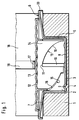
Bei dem in Figur 1 gezeigten Ausführungsbeispiel weist der Gerätefuß 1 des Heißgetränkebereiters einen zylindrischen, nach oben offenen Aufnahmeraum 2 auf, der von einer im Gerätefuß 1 angeordneten Ausnehmung gebildet wird. Auf der ebenen Bodenfläche 3 des Aufnahmeraums 2 sind in gleichmäßigem Abstand voneinander und von der Zylinderachse drei Vorsprünge 4 mit kugeliger Oberfläche angeordnet. In dem Aufnahmeraum 2 befindet sich ein zylindrischer Topf 5 einer Auffangschale 6. Der Außendurchmesser des Topfes 5 ist nur um das erforderliche Bewegungsspiel kleiner als der Innendurchmesser des Aufnahmeraums 2, so daß die Auffangschale 6 in dem Aufnahmeraum 2 leicht drehbar ist.In the exemplary embodiment shown in FIG. 1, the
Der Rand des Topfes 5 ist als kreisringförmige Scheibe 7 ausgebildet, die sich über den Außenrand des Gerätefußes 1 hinaus erstreckt und trichterartig zum Topf 5 hin geneigt ist. Der Boden 8 des Topfes 5 weist auf seiner Unterseite kugelkalottenförmige Ausnehmungen 9 auf, die durch Hochwölbungen des Bodens 8 gebildet sind. Die Zahl der Ausnehmungen 9 beträgt wenigstens drei oder ein Vielfaches davon und jeweils drei Ausnehmungen 9 sind in der gleichen Weise positioniert wie die Vorsprünge 4. Die Ausnehmungen 9 bilden mit den Vorsprüngen 4 ein Rastgesperre, indem die drei Vorsprünge 4 jeweils in drei Ausnehmungen 9 einrasten. Sind drei Ausnehmungen 9 vorhanden, so ergeben sich drei Winkelstellungen im Abstand von 120°, in denen die Auffangschale 6 durch das Rastgesperre gehalten werden kann. Durch eine höhere Zahl von Ausnehmungen 9, beispielsweise sechs oder neun, ergibt sich eine größere Zahl von Raststellungen mit entsprechend feinerer Abstufung. An der Innenwand des Topfes 5 befinden sich in gleichmäßigem Abstand voneinander drei zur Zylinderachse parallele Rippen 10, deren dem Topfrand benachbarte Enden eine gewölbte Gegenfläche 11 für einen Schraubentrieb bilden.The edge of the
Die Auffangschale 6 trägt eine Abstellplatte 12 mit Ablaufschlitzen 13. Die Abstellplatte 12 hat an ihrer Unterseite einen zylindrischen Kragen 14, der in den Topf 5 eingreift und an der Innenwand des Topfes 5 geführt ist. Der Kragen 14 weist drei Ausschnitte 15 auf, durch die drei vergleichsweise steile Schraubenflächen 16 gebildet werden. Die Schraubenflächen 16 wirken mit den Gegenflächen 11 der Rippen 10 zusammen, wodurch ein Schraubentrieb gebildet wird, der bei einer Drehung der Auffangschale 6 gegenüber der Abstellplatte 12 die Abstellplatte 12 in Richtung der Zylinderachse gegenüber der Auffangschale 6 bewegt. Selbstverständlich sind auch äquivalente Schraubentriebe möglich. Die Abstellplatte 12 ist durch einen in radialer Richtung über die Scheibe 7 hinausragenden Ansatz 17 an einer Drehung gegenüber dem Gehäuse 18 des Heißgetränkebereiters gehindert, indem der Ansatz 17 in eine vertikale Führungsnut 19 des Gehäuses 18 eingreift.The
In Figur 1 ist die Abstellplatte 12 in ihrer niedrigsten Stellung gezeigt, wobei sie mit dem Kragen 14 auf den Rippen 10 ruht. Um die Abstellplatte 12 in eine höhere Lage zu bringen, wird die Auffangschale 6 im Uhrzeigersinn gedreht, wobei sie am Außenrand der Scheibe 7 gegriffen werden kann. Durch eine solche Drehung bewegen sich die Rippen 10 gegen die Schraubenflächen 16 und die Gegenflächen 11 gleiten an den Schraubenflächen 16 entlang und bewirken dadurch ein Anheben der Abstellplatte 12, wenn diese über ihren Ansatz 17 in der Führungsnut 19 dabei nach oben entlang gleitet und dadurch drehfest am Gehäuse 18 gehalten wird. Bei der Drehung werden die Ausnehmungen 9 von den Vorsprüngen 4 abgehoben und der Boden 8 gleitet über die Vorsprünge 4 hinweg, bis nach einem Drehwinkel von beispielsweise 120° die Ausnehmungen 9 wieder auf die Vorsprünge 4 aufrasten. Je nach Größe des Drehwinkels, um den die Auffangschale 6 verdreht worden ist, ergibt sich eine unterschiedliche Höhenlage der Abstellplatte 12. Die maximale Hubhöhe der Abstellplatte 12 wird durch die Höhe der Schraubenfläche 16 bestimmt.In Figure 1, the
Das Festhalten der Abstellplatte 12 in einer angehobenen Stellung wird allein durch das Eingreifen der Vorsprünge 4 in die Ausnehmungen 9 gewährleistet, da die Steigung der Schraubenflächen 16 außerhalb des Selbsthemmungsbereichs liegt. Die Vorsprünge 4 werden durch das Eigengewicht der Auffangschale 6 und der Abstellplatte 12 in Eingriff gehalten. Beim Aufstellen eines Auffanggefäßes auf die Abstellplatte 12 wird durch dessen Gewicht der Eingriff entsprechend verstärkt. Durch Drehung der Auffangschale 6 entgegen dem Uhrzeigersinn kann die Abstellplatte 12 wieder abgesenkt werden. Die Abstellplatte 12 wird an ihrer zylindrisch ausgebildeten Mantelfläche des Kragens 14 in der zylindrischen Ausnehmung 2 ausreichend geführt, so daß auch bei vollständig ausgefahrener Abstellplatte 12 diese noch nicht kippt. Hierzu können auch gesonderte Führungseinrichtungen (nicht dargestellt) in Form etwa einer Kulissenführung verwendet werden.The holding of the
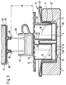
Der grundsätzliche Aufbau und die Wirkungsweise der in Figur 2 dargestellten Variante stimmt mit dem Ausführungsbeispiel gemäß Figur 1 überein. Die bauliche Gestaltung des Rastgesperres und des Schraubentriebs ist jedoch abweichend.The basic structure and the mode of operation of the variant shown in FIG. 2 correspond to the exemplary embodiment according to FIG. 1. However, the design of the locking mechanism and the screw drive is different.
So sind zur Bildung des Rastgesperres in der Bodenfläche 3 des Gerätefußes 1 kugelkalottenförmige Ausnehmungen 20 in gleichmäßigem Umfangsabstand voneinander vorgesehen und der Boden 8 der Auffangschale 6 hat an seiner Unterseite entsprechend positionierte, kugelige Vorsprünge 21, die in die Ausnehmungen 20 einrasten.Thus, to form the locking mechanism in the bottom surface 3 of the
Die Schraubenflächen 16 des Schraubentriebs sind durch nach innen vorspringende Stufen 22 in der Wand des Topfes 5 gebildet und der Kragen 14 der Abstellplatte 12 weist an seiner Außenseite Rippen 23 auf, die an ihren unteren Enden die Gegenflächen 11 haben. Da hierbei der Kragen 14 nicht durch Ausschnitte 15 unterbrochen ist, kann seine Wandstärke geringer sein.The screw surfaces 16 of the screw drive are formed by inwardly projecting
Zur Verbesserung der Führung der Abstellplatte 12 an der Auffangschale 6 weist die Auffangschale 6 koaxial zur Zylinderachse einen zylindrischen Lagerzapfen 24 auf, der in eine an der Unterseite der Abstellplatte 12 angeordnete Führungshülse 25 eingreift. Der Lagerzapfen 24 und die Führungshülse 25 haben einen in Bezug auf die Führungslänge günstigen Durchmesser und sorgen dadurch für eine klemmfreie Führung der Abstellplatte 12.To improve the guidance of the
In Fig. 2 ist auf der Abstellplatte 12 ein in Form einer Espressotasse ausgebildeter Auffangbehälter 27 abgestellt, der mit seinem Rand 28 unterhalb der zwei nebeneinander angeordneten Austrittsöffnungen 26 angeordnet ist. Die Austrittsöffnungen 26 sind Teil eines Siebkorbträgers 29, in dem am Boden 30 ein Sieb 31 eingesetzt ist, auf dem das Espressomehl 32 ruht. Der Siebkorbträger 29 ist in eine in der Zeichnung nicht dargestellte Siebkorbhalteeinrichtung einer Espressomaschine eingesetzt, so daß die in der Zeichnung dargestellte Position sich ergibt. Auf weitere Einzelheiten einer Espressomaschine wird hier nicht näher eingegangen, da sie bereits, wie eingangs erwähnt, allgemein bekannt ist. Bei Höhenverstellung der Abstellplatte 12 wandern die Rippen 23 mit Ihren Gegenflächen 11 auf den Schraubenflächen 16 auf bzw. ab, so daß sich der Abstand X verkleinert bzw. vergrößert. Dadurch kann der Rand 28 der Espressotasse 27 ausreichend nahe an die Austrittsöffnungen 26 herangeführt werden, so daß beim Eingießen Wärmeverluste und ein Danebenspritzen bzw. -laufen vermieden werden.In FIG. 2, a collecting
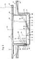
In dem Ausführungsbeispiel nach Fig. 3 wurden für gleich Bauteile gleiche Positionsnummern gewählt. Bei diesem Ausführungsbeispiel wurde der Einfachheit halber der Gerätefuß 1 mit seinem Aufnahmeraum 2, wie er in Fig. 1 dargestellt und in der zugehörigen Beschreibung beschrieben ist, weggelassen. Bei diesem Ausführungsbeispiel ist die Abstellfläche 12 teilweise aus der Auffangchale 6 herausgefahren und die an der Innenwandung des Aufnahmeraums 2 der Auffangschale 6 ausgebildeten Schraubenflächen 16 bestehen aus je zwei nach innen hervorspringenden und parallel zueinander verlaufenden Wandflächen 34, 35, zwischen denen eine Gewindenut 37 ausgebildet ist, die Teil eines nicht-selbsthemmenden Gewindeganges bilden.In the exemplary embodiment according to FIG. 3, identical position numbers have been selected for identical components. In this exemplary embodiment, the
An der Innenwandung des Aufnahmeraumes 2 sind um 120° am Umfang versetzt angeordnete, drei Schraubenflächen 16 gleicher Steigung ausgebildet, die auf gleicher Höhe in Nähe des Bodens 8 beginnen und etwa in Höhe der kreisringförmigen Scheibe 7 an der Innenwandung des Aufnahmeraums 2 enden. In Fig. 3 sind, wie in den Figuren 1 und 2, nur zwei Gewindegänge 11, 16 ersichtlich, denn der dritte Gewindegang liegt außerhalb der Zeichenebene und ist daher hier nicht sichtbar. Die Gewindeanfänge 40 werden durch die Gewindenuten 37 offengehalten, so daß die an der Außenfläche des zylindrischen Kragens 14 ausgebildeten Zapfen 41 mit ihren nach oben und unten gerichteten Gegenflächen 11 in die Gewindenuten 37 durch Drehung der Auffangschale 6 entgegen dem Uhrzeigersinn in diese eingebracht werden können, um dann bei weiterer Drehung der Auffangschale 6 die Abstellplatte 12 in ihrer Höhe nach oben zu verschieben, wenn diese durch eine Führungsnut oder einen Zapfen 19 drehgesichert ist. Dabei stützt sich der Boden 8 der Auffangschale 6 über die kugeligen Vorsprünge 21 in am Boden des Gerätefußes 1 ausgebildete, ebenfalls kugelige Vertiefungen, wie sie in Fig. 1 dargestellt sind, ab.On the inner wall of the receiving
Die oberen freien Enden der Gewindenuten 37 sind durch eine Wand 39 nach außen begrenzt, so daß, wenn die Abstellplatte 12 ganz nach oben herausgedreht wurde, die Zapfen 41 an den Wänden 39 anschlagen, wodurch keine weitere Verdrehung der Abstellplatte 12 mehr möglich ist.The upper free ends of the threaded
Wie aus Fig. 3 deutlich ersichtlich ist, werden die unteren Wandflächen 35 dadurch gebildet, daß die unterhalb der Wandflächen 35 gebildeten Abschnitte 36 zur Mittellinie 42 hin eingezogen und konzentrisch zu dieser bzw. zur Wandfläche des Topfes 5 verlaufen. Von außen betrachtet, bilden die eingezogenen Vertiefungen 36 die Form je eines rechtwinkligen Dreiecks, wobei die Hypotenuse die Seite darstellt, die die untere Wandfläche 35 bildet.As can be clearly seen from FIG. 3, the lower wall surfaces 35 are formed in that the
An die Zapfen 41 schließen sich die Ausnehmungen 43 an, in die die oberen Wandflächen 34 eingreifen. Etwa in gleicher Abmessung im Längsschnitt wie die Zapfen 41 schließen sich an die Ausnehmungen 43 nach oben Stege 38 an, die zum Zwecke der Führung für die Abstellplatte 12 an der Innenwandung des Topfes 5 der Auffangschale 6 gleitend anliegen, was allerdings in Fig. 3 nicht dargestellt ist, da zwischen diesen Bereichen stets ein geringes Spiel vorhanden sein muß, um ein Klemmen zu verhindern.The
Beim Einsetzen der Abstellplatte 12 über den Kragen 14 in den Aufnahmeraum 2 müssen die Zapfen 41 in dem Bereich angeordnet sein, der sich zwischen der Linie 44 und dem Gewindeeintritt 40 ergibt, d.h., außerhalb der senkrechten Projektion der Gewindegänge 16. Die kugeligen Vorsprünge 21 bilden Rastelemente, wie sie in Fig. 1 beschrieben sind, so daß an dieser Stelle darauf nicht mehr eingegangen wird.When inserting the
Claims (24)
dadurch gekennzeichnet,
daß die Abstützung der Abstellplatte (12) auf dem Gerätefuß (1) über eine dazwischen liegendene Auffangschale (6) erfolgt, die den Aufnahmeraum (2) für die überschüssige Flüssigkeit bildet t und die mit dem Gerätefuß (1) lösbar verbunden ist, daß auch die Abstellplatte (12) lösbar mit der Auffangschale (6) verbunden ist, daß die Höhenverstelleinrichtung auf der Grundlage eines Schraubentriebs (11, 16) arbeitet und daß der Schraubentrieb (11, 16) entweder zwischen dem Gerätefuß (1) und der Auffangschale (6) oder zwischen der Auffangschale (6) und der Abstellplatte (12) wirkt, wobei im ersten Fall Gerätefuß (1) und Auffangschale (6) und im zweiten Fall Auffangschale (6) und Abstellplatte (12) relativ gegeneinander beweglich sind.Espresso machine with an outlet opening (26) for the prepared espresso drink and a storage plate (12) arranged under the outlet opening (26) at a distance (X), which is supported by a device base (1) and on which a receptacle (27) holding the drink can be shut off, a receiving space (2) for excess liquid being present underneath the shelf (12) and a mechanical height adjustment device being provided between the shelf (12) and the device base (1), which enables the distance (X) to be changed,
characterized,
that the support of the storage plate (12) on the device base (1) via an intermediate collecting tray (6), which forms the receiving space (2) for the excess liquid t and which is detachably connected to the device base (1) that also the storage plate (12) is detachably connected to the drip tray (6), that the height adjustment device works on the basis of a screw drive (11, 16) and that the screw drive (11, 16) either between the device base (1) and the drip tray (6 ) or between the collecting tray (6) and the storage plate (12), whereby in the first case the device base (1) and the collecting tray (6) and in the second case the collecting tray (6) and the storage plate (12) can be moved relative to one another.
dadurch gekennzeichnet,
daß der Schraubentrieb (11, 16) zwischen der Auffangschale (6) und der Abstellfläche (12) ausgebildet ist.Espresso machine according to Aspruch 1,
characterized,
that the screw drive (11, 16) between the drip tray (6) and the shelf (12) is formed.
dadurch gekennzeichnet
daß sich bei Betätigung des Schraubentriebs (11, 16) die Abstellplatte (12) gegenüber der Auffangschale (6) verdreht.Espresso machine according to claim 2,
characterized
that when the screw drive (11, 16) is actuated, the storage plate (12) rotates relative to the collecting tray (6).
dadurch gekennzeichnet,
daß sich bei Betätigung des Schrauentriebs (11, 16) die Auffangschale (6) gegenüber der Arbeitsplatte (12) verdreht.Espresso machine according to claim 2,
characterized,
that when the screw drive (11, 16) is actuated, the drip tray (6) rotates relative to the worktop (12).
dadurch gekennzeichnet,
daß der Schraubentrieb (11, 16) zwischen dem Gerätefuß (1) und der Auffangschale (6) angeordnet ist.Espresso machine according to claim 1,
characterized,
that the screw drive (11, 16) between the device base (1) and the drip tray (6) is arranged.
dadurch gekennzeichnet,
daß sich bei Betätigung des Schraubentriebs (11, 16) die Auffangschale (6) gegenüber dem Gerätefuß (1) verdreht.Espresso machine according to claim 5,
characterized,
that when the screw drive (11, 16) is actuated, the drip tray (6) rotates relative to the device base (1).
dadurch gekennzeichnet,
daß der Schraubentrieb (11, 16) aus einem selbsthemmenden Gewinde besteht.Espresso machine according to claim 2 or 5,
characterized,
that the screw drive (11, 16) consists of a self-locking thread.
dadurch gekennzeichnet,
daß der Schraubentrieb (11, 16) aus einem nicht-selbsthemmenden Gewinde besteht.Espresso machine according to claim 2 or 5,
characterized,
that the screw drive (11, 16) consists of a non-self-locking thread.
dadurch gekennzeichnet,
daß der Schraubentrieb (11, 16) durch ein Rastgesperre (4, 9; 20,21) in mehreren Winkelstellungen arretierbar ist.Espresso machine according to claim 7 or 8,
characterized,
that the screw drive (11, 16) can be locked in several angular positions by a locking mechanism (4, 9; 20, 21).
dadurch gekennzeichnet,
daß die Abstellplatte (12) gegenüber der Auffangschale (6) durch eine Vertikalführung (17, 19) an einer Drehung gegenüber dem Gerätefuß (1) bzw. dem Gehäuse der Espressomaschine gehindert ist.Espresso machine according to claim 4,
characterized,
that the storage plate (12) relative to the drip tray (6) is prevented from rotating by a vertical guide (17, 19) relative to the appliance base (1) or the housing of the espresso machine.
dadurch gekennzeichnet,
daß die Auffangschale (6) gegenüber der Abstellplatte (12) im Gerätefuß (1) bzw. am Gehäuse der Espressomaschine an einer Drehung gehindert ist.Espresso machine according to claim 3,
characterized,
that the drip tray (6) is prevented from rotating relative to the storage plate (12) in the appliance base (1) or on the housing of the espresso machine.
dadurch gekennzeichnet,
daß der Boden (8) der Auffangschale (6) auf seiner Unterseite Vorsprünge (21) bzw. Ausnehmungen (9) aufweist, denen an der Bodenfläche (3) des Gerätefußes (1) ausgebildete und komplementär geformte Ausnehmungen (20) bzw. Vorsprünge (4) gegenüberliegen.Espresso machine according to claim 9,
characterized,
that the bottom (8) of the collecting tray (6) has on its underside projections (21) or recesses (9), which are formed on the bottom surface (3) of the device base (1) and have complementarily shaped recesses (20) or projections ( 4) face each other.
dadurch gekennzeichnet,
daß der Schraubentrieb (11, 16) mehrere Schraubengänge aufweist.Espresso machine according to claim 2 or 5,
characterized,
that the screw drive (11, 16) has several screw turns.
dadurch gekennzeichnet,
daß die Auffangschale (6) einen zylindrischen Topf (5) aufweist und daß die Abstellplatte (12) an ihrer Unterseite mit einem zylindrischen Ansatz (14) versehen ist, der längsverschieblich und über den Schraubentrieb (11, 16) in dem Topf (5) der Auffangschale (6) gelagert ist, wobei am Topf (5) oder am Ansatz (14) Schraubenflächen (16) vorgesehen sind, die mit Gegenflächen (11) am Ansatz (14) oder am Topf (5) den Schraubentrieb bilden.Espresso machine according to claim 2,
characterized by
that the collecting tray (6) has a cylindrical pot (5) and that the storage plate (12) is provided on its underside with a cylindrical projection (14) which is longitudinally displaceable and via the screw drive (11, 16) in the pot (5) the drip tray (6) is mounted, with the pot (5) or screw surfaces (16) are provided on the shoulder (14), which form the screw drive with counter surfaces (11) on the shoulder (14) or on the pot (5).
dadurch gekennzeichnet,
daß der Ansatz der Abstellplatte (12) als zylindrischer Kragen (14) ausgebildet ist und daß die Schraubenflächen (16) durch Ausschnitte in dem Kragen (14) gebildet sind.Espresso machine according to claim 14,
characterized,
that the approach of the storage plate (12) is designed as a cylindrical collar (14) and that the screw surfaces (16) are formed by cutouts in the collar (14).
dadurch gekennzeichnet,
daß die Schraubenflächen (16) durch nach innen vorspringende Stufen (22) in der Wand des Topfes (5) gebildet sind.Espresso machine according to claim 14,
characterized,
that the screw surfaces (16) are formed by inwardly projecting steps (22) in the wall of the pot (5).
dadurch gekennzeichnet,
daß die Gegenflächen (11) durch die Enden von zur Schraubenachse parallelen Rippen (10, 23) an der Innenwand des Topfes (5) oder der Außenwand des Ansatzes (14) gebildet sind.Espresso machine according to one of claims 12 to 14,
characterized,
that the counter surfaces (11) are formed by the ends of ribs (10, 23) parallel to the screw axis on the inner wall of the pot (5) or the outer wall of the extension (14).
dadurch gekennzeichnet,
daß die Schraubenflächen (16) durch je zwei nach innen hervorspringende und parallel zueinander verlaufende Wandflächen (34, 35) gebildet werden, die je eine Gewindenut (37) bilden, in die an der Außenfläche des Kragens (14) hervorspringende Zapfen (41) mit ihren Gegenflächen (11) eingreifen.Espresso machine according to claim 12,
characterized,
that the screw surfaces (16) are each formed by two inwardly projecting and parallel wall surfaces (34, 35), each forming a threaded groove (37), in the projecting on the outer surface of the collar (14) with pins (41) engage their counter surfaces (11).
dadurch gekennzeichnet,
daß die untere Wandfläche (35) durch eine angeformte Vertiefung (36) am Topf (5) gebildet wird.Espresso machine according to claim 18,
characterized,
that the lower wall surface (35) is formed by a molded recess (36) on the pot (5).
dadurch gekennzeichnet,
daß jede obere Wandfläche (34) durch eine an der Innenwandung des Topfes (5) angeformte Rippe gebildet wird.Espresso machine according to claim 18,
characterized,
that each upper wall surface (34) is formed by a rib formed on the inner wall of the pot (5).
dadurch gekennzeichnet,
daß an der Außenfläche des Kragens (14) mindestens drei am Umfang verteilte und nach oben sich erstreckende Stege (38) ausgebildet sind, die an der Innenwand des Topfes (5) der Auffangschale (6) gleitend anliegen.Espresso machine according to claim 18,
characterized,
that on the outer surface of the collar (14) at least three circumferentially distributed and upwardly extending webs (38) are formed, which slide against the inner wall of the pot (5) of the collecting tray (6).
dadurch gekennzeichnet,
daß die Gewindenuten (37) an ihren dem Boden (8) nahen Ende offen sind und an ihren anderen, oberen Enden von einer Wand (39) verschlossen sind.Espresso machine according to claim 20,
characterized,
that the threaded grooves (37) are open at their end near the bottom (8) and are closed at their other, upper ends by a wall (39).
dadurch gekennzeichnet,
daß eine zentrale, aus Lagerzapfen (24) und Führungshülse (25) bestehende Teleskopführung geringen Durchmessers vorgesehen ist, die einerseits mit der Abstellplatte (12) und andererseits mit der Auffangschale (6) verbunden ist.Espresso machine according to claim 2,
characterized,
that a central, made of bearing pin (24) and guide sleeve (25) existing telescopic guide of small diameter is provided, which is connected on the one hand to the storage plate (12) and on the other hand to the drip tray (6).
dadurch gekennzeichnet,
daß die Vertikalführung aus einem an der Abstellplatte (12) ausgebildeten radialen Ansatz (17) besteht, der in einen nach außen offenen vertikalen Schacht (19) im Gehäuse (18) des Geräts eingreift.Espresso machine according to claim 10,
characterized,
that the vertical guide consists of a radial shoulder (17) formed on the storage plate (12), which engages in an outwardly open vertical shaft (19) in the housing (18) of the device.
Applications Claiming Priority (2)
| Application Number | Priority Date | Filing Date | Title |
|---|---|---|---|
| DE4226151A DE4226151A1 (en) | 1992-08-07 | 1992-08-07 | Espresso machine for preparing hot drinks |
| DE4226151 | 1992-08-07 |
Publications (2)
| Publication Number | Publication Date |
|---|---|
| EP0585607A1 true EP0585607A1 (en) | 1994-03-09 |
| EP0585607B1 EP0585607B1 (en) | 1995-03-15 |
Family
ID=6465065
Family Applications (1)
| Application Number | Title | Priority Date | Filing Date |
|---|---|---|---|
| EP93112123A Expired - Lifetime EP0585607B1 (en) | 1992-08-07 | 1993-07-29 | Espresso coffee machine |
Country Status (4)
| Country | Link |
|---|---|
| EP (1) | EP0585607B1 (en) |
| AT (1) | ATE119753T1 (en) |
| DE (2) | DE4226151A1 (en) |
| ES (1) | ES2070019T3 (en) |
Cited By (10)
| Publication number | Priority date | Publication date | Assignee | Title |
|---|---|---|---|---|
| FR2806605A1 (en) | 2000-03-27 | 2001-09-28 | Moulinex Sa | INFUSION MACHINE |
| EP1639926A1 (en) | 2004-09-24 | 2006-03-29 | Fianara International B.V. | Coffee apparatus with a height-adustable collecting bowl |
| WO2006043194A1 (en) * | 2004-10-18 | 2006-04-27 | Koninklijke Philips Electronics N.V. | Beverage supplying device having a drip tray comprising a convex droplet landing surface |
| DE102006049893B3 (en) * | 2006-10-23 | 2008-03-27 | BSH Bosch und Siemens Hausgeräte GmbH | Holding device for use in beverage machine, comprises dripping plate and cup body that is formed between upper and lower position for adjusting and turning |
| US7681491B2 (en) | 2004-11-11 | 2010-03-23 | Nestec S.A. | Self-cleaning mixing head for producing a milk-based mixture |
| US8091469B2 (en) * | 2005-06-07 | 2012-01-10 | Nestec S.A. | Beverage machine with drip tray device for recipients of different heights |
| WO2012110287A1 (en) * | 2011-02-14 | 2012-08-23 | BSH Bosch und Siemens Hausgeräte GmbH | Beverage container storage device |
| US9844293B2 (en) | 2015-03-06 | 2017-12-19 | Spectrum Brands, Inc. | Apparatus for dispensing beverages |
| WO2019110535A1 (en) * | 2017-12-05 | 2019-06-13 | Nestec S.A. | A telescopic cup tray for a beverage machine |
| WO2020035735A3 (en) * | 2018-08-17 | 2020-05-07 | Lavazza Professional Uk Limited | Beverage vessel support apparatus |
Families Citing this family (4)
| Publication number | Priority date | Publication date | Assignee | Title |
|---|---|---|---|---|
| FR2732879B1 (en) * | 1995-04-14 | 1997-06-13 | Seb Sa | HOT BEVERAGE MACHINE, IN PARTICULAR COFFEE MACHINE, COMPRISING A DEVICE FOR ADJUSTING THE HEIGHT OF THE COFFEE DISPENSING |
| CN103002783B (en) * | 2010-07-12 | 2016-08-17 | 雀巢产品技术援助有限公司 | Firm cup supporting member for beverage machine |
| EP2987437A1 (en) * | 2014-08-22 | 2016-02-24 | Capitani S.r.l. | Machine for the preparation of an infused drink |
| IT202100020897A1 (en) * | 2021-08-03 | 2023-02-03 | Illycaffe’ Spa | Machine for dispensing a drink |
Citations (6)
| Publication number | Priority date | Publication date | Assignee | Title |
|---|---|---|---|---|
| DE7915161U1 (en) * | 1979-05-25 | 1979-08-23 | Gruetzmacher, Bernd, 2000 Hamburg | Coffee and / or espresso machine |
| DE2922022A1 (en) * | 1979-05-30 | 1980-12-11 | Wmf Wuerttemberg Metallwaren | COFFEE MACHINE |
| DE2944264A1 (en) * | 1979-11-02 | 1981-05-14 | Fa. Robert Krups, 5650 Solingen | Domestic coffee maker with through-flow water heater - has wall fixing socket and telescopic support plate for reception jug |
| EP0279782A1 (en) * | 1987-02-20 | 1988-08-24 | Lükon Fabrik für elektrothermische Apparate und elektrische Stabheizkörper Paul Lüscher | Device for heating water or drinks |
| JPH02102614A (en) * | 1988-10-12 | 1990-04-16 | Tokyo Gas Co Ltd | Hot water supplying device |
| DE9109023U1 (en) * | 1991-07-22 | 1992-11-19 | Bosch-Siemens Hausgeraete Gmbh, 8000 Muenchen, De |
-
1992
- 1992-08-07 DE DE4226151A patent/DE4226151A1/en not_active Withdrawn
-
1993
- 1993-07-29 EP EP93112123A patent/EP0585607B1/en not_active Expired - Lifetime
- 1993-07-29 DE DE59300106T patent/DE59300106D1/en not_active Expired - Fee Related
- 1993-07-29 ES ES93112123T patent/ES2070019T3/en not_active Expired - Lifetime
- 1993-07-29 AT AT93112123T patent/ATE119753T1/en not_active IP Right Cessation
Patent Citations (6)
| Publication number | Priority date | Publication date | Assignee | Title |
|---|---|---|---|---|
| DE7915161U1 (en) * | 1979-05-25 | 1979-08-23 | Gruetzmacher, Bernd, 2000 Hamburg | Coffee and / or espresso machine |
| DE2922022A1 (en) * | 1979-05-30 | 1980-12-11 | Wmf Wuerttemberg Metallwaren | COFFEE MACHINE |
| DE2944264A1 (en) * | 1979-11-02 | 1981-05-14 | Fa. Robert Krups, 5650 Solingen | Domestic coffee maker with through-flow water heater - has wall fixing socket and telescopic support plate for reception jug |
| EP0279782A1 (en) * | 1987-02-20 | 1988-08-24 | Lükon Fabrik für elektrothermische Apparate und elektrische Stabheizkörper Paul Lüscher | Device for heating water or drinks |
| JPH02102614A (en) * | 1988-10-12 | 1990-04-16 | Tokyo Gas Co Ltd | Hot water supplying device |
| DE9109023U1 (en) * | 1991-07-22 | 1992-11-19 | Bosch-Siemens Hausgeraete Gmbh, 8000 Muenchen, De |
Non-Patent Citations (1)
| Title |
|---|
| PATENT ABSTRACTS OF JAPAN vol. 14, no. 306 (C - 0735) 3 July 1990 (1990-07-03) * |
Cited By (22)
| Publication number | Priority date | Publication date | Assignee | Title |
|---|---|---|---|---|
| WO2001072190A1 (en) | 2000-03-27 | 2001-10-04 | Seb S.A. | Infusion machine |
| US6766729B2 (en) | 2000-03-27 | 2004-07-27 | Seb S.A. | Infusion machine |
| FR2806605A1 (en) | 2000-03-27 | 2001-09-28 | Moulinex Sa | INFUSION MACHINE |
| EP1639926A1 (en) | 2004-09-24 | 2006-03-29 | Fianara International B.V. | Coffee apparatus with a height-adustable collecting bowl |
| CN1751637B (en) * | 2004-09-24 | 2010-05-05 | 萨科Ipr有限公司 | Coffee apparatus with a height-adustable collecting bowl |
| WO2006043194A1 (en) * | 2004-10-18 | 2006-04-27 | Koninklijke Philips Electronics N.V. | Beverage supplying device having a drip tray comprising a convex droplet landing surface |
| US7823501B2 (en) | 2004-10-18 | 2010-11-02 | Koninklijke Philips Electronics N.V. | Beverage supplying device having a drip tray comprising a convex droplet landing surface |
| US8333144B2 (en) | 2004-11-11 | 2012-12-18 | Nestec S.A. | Beverage machine with drip collecting device |
| US7681491B2 (en) | 2004-11-11 | 2010-03-23 | Nestec S.A. | Self-cleaning mixing head for producing a milk-based mixture |
| EP2218378A2 (en) | 2004-11-11 | 2010-08-18 | Nestec S.A. | Beverage machine with height-adjustable device for controlling distance between beverage recipient and outlet |
| US8091469B2 (en) * | 2005-06-07 | 2012-01-10 | Nestec S.A. | Beverage machine with drip tray device for recipients of different heights |
| US8770093B2 (en) | 2005-06-07 | 2014-07-08 | Nestec S.A. | Beverage machine with drip tray device for recipients of different heights |
| DE102006049893B3 (en) * | 2006-10-23 | 2008-03-27 | BSH Bosch und Siemens Hausgeräte GmbH | Holding device for use in beverage machine, comprises dripping plate and cup body that is formed between upper and lower position for adjusting and turning |
| WO2012110287A1 (en) * | 2011-02-14 | 2012-08-23 | BSH Bosch und Siemens Hausgeräte GmbH | Beverage container storage device |
| US9844293B2 (en) | 2015-03-06 | 2017-12-19 | Spectrum Brands, Inc. | Apparatus for dispensing beverages |
| WO2019110535A1 (en) * | 2017-12-05 | 2019-06-13 | Nestec S.A. | A telescopic cup tray for a beverage machine |
| CN111343889A (en) * | 2017-12-05 | 2020-06-26 | 雀巢产品有限公司 | Telescopic cup holder for beverage machine |
| US11470996B2 (en) | 2017-12-05 | 2022-10-18 | Societe Des Produits Nestle S.A. | Telescopic cup tray for a beverage machine |
| WO2020035735A3 (en) * | 2018-08-17 | 2020-05-07 | Lavazza Professional Uk Limited | Beverage vessel support apparatus |
| CN112770655A (en) * | 2018-08-17 | 2021-05-07 | 拉瓦萨专业英国有限公司 | Beverage container supporting device |
| JP2021534048A (en) * | 2018-08-17 | 2021-12-09 | ラバッツァ プロフェッショナル ユーケー リミテッド | Beverage container support device |
| US11918138B2 (en) | 2018-08-17 | 2024-03-05 | Luigi Lavazza S.P.A. | Beverage vessel support apparatus |
Also Published As
| Publication number | Publication date |
|---|---|
| ES2070019T3 (en) | 1995-05-16 |
| ATE119753T1 (en) | 1995-04-15 |
| DE59300106D1 (en) | 1995-04-20 |
| DE4226151A1 (en) | 1994-02-10 |
| EP0585607B1 (en) | 1995-03-15 |
Similar Documents
| Publication | Publication Date | Title |
|---|---|---|
| EP0585607B1 (en) | Espresso coffee machine | |
| EP0423457B1 (en) | Electrically operated citrus press | |
| EP0293580B1 (en) | Apparatus for grating or cutting food stuff, in particular kitchen apparatus | |
| DE19832063C5 (en) | Espressobrühkopfeinheit | |
| DE60104300T2 (en) | An infusion machine | |
| DE2548812B2 (en) | Pepper mill or the like. with two interconnected, relatively rotatable housing parts | |
| WO1990009133A1 (en) | Cooking receptacle | |
| EP3766391B1 (en) | Device for preparing coffee | |
| EP0220688B1 (en) | Machine for making coffee or tea | |
| DE3644267A1 (en) | Cutting insert for a working container of a food processor | |
| DE3632688C1 (en) | Flour mill for an electrically driven kitchen machine | |
| DE3422011A1 (en) | Cooking vessel | |
| DE202022102226U1 (en) | Kitchen utensil with lid holder and lid holder | |
| DE102006049893B3 (en) | Holding device for use in beverage machine, comprises dripping plate and cup body that is formed between upper and lower position for adjusting and turning | |
| DE102021133074A1 (en) | Powder holder for a beverage maker | |
| DE2931859A1 (en) | Counter top electric deep fryer - has side attachments providing handles, hinge mountings for cover and basket and housing control circuit | |
| DE19741632A1 (en) | Mill for grinding granular material | |
| DE4111310C2 (en) | Grinding attachment for household food processors | |
| EP1769698A1 (en) | Cosmetic application container, especial lip pomade, preferably in stick form | |
| DE202020107514U1 (en) | Machine for the production of infused beverages with a carafe arranged on a receiving base | |
| DE3609393C1 (en) | Grinding mill for an electrically driven kitchen appliance | |
| DE3101091A1 (en) | Frying pan | |
| DE10001475B4 (en) | table | |
| DE19505344C1 (en) | Coupling for rotary machine for cleaning hard surfaces | |
| DE3216373A1 (en) | Electric coffee machine |
Legal Events
| Date | Code | Title | Description |
|---|---|---|---|
| PUAI | Public reference made under article 153(3) epc to a published international application that has entered the european phase |
Free format text: ORIGINAL CODE: 0009012 |
|
| AK | Designated contracting states |
Kind code of ref document: A1 Designated state(s): AT CH DE ES FR IT LI PT |
|
| 17P | Request for examination filed |
Effective date: 19940328 |
|
| 17Q | First examination report despatched |
Effective date: 19940704 |
|
| ITF | It: translation for a ep patent filed |
Owner name: DE DOMINICIS & MAYER S.R.L. |
|
| GRAA | (expected) grant |
Free format text: ORIGINAL CODE: 0009210 |
|
| AK | Designated contracting states |
Kind code of ref document: B1 Designated state(s): AT CH DE ES FR IT LI PT |
|
| REF | Corresponds to: |
Ref document number: 119753 Country of ref document: AT Date of ref document: 19950415 Kind code of ref document: T |
|
| REF | Corresponds to: |
Ref document number: 59300106 Country of ref document: DE Date of ref document: 19950420 |
|
| REG | Reference to a national code |
Ref country code: ES Ref legal event code: FG2A Ref document number: 2070019 Country of ref document: ES Kind code of ref document: T3 |
|
| ET | Fr: translation filed | ||
| RAP2 | Party data changed (patent owner data changed or rights of a patent transferred) |
Owner name: BRAUN AKTIENGESELLSCHAFT |
|
| REG | Reference to a national code |
Ref country code: CH Ref legal event code: PFA Free format text: BRAUN AKTIENGESELLSCHAFT TRANSFER- BRAUN AKTIENGESELLSCHAFT |
|
| PLBE | No opposition filed within time limit |
Free format text: ORIGINAL CODE: 0009261 |
|
| STAA | Information on the status of an ep patent application or granted ep patent |
Free format text: STATUS: NO OPPOSITION FILED WITHIN TIME LIMIT |
|
| 26N | No opposition filed | ||
| PGFP | Annual fee paid to national office [announced via postgrant information from national office to epo] |
Ref country code: PT Payment date: 19980630 Year of fee payment: 6 |
|
| PG25 | Lapsed in a contracting state [announced via postgrant information from national office to epo] |
Ref country code: PT Free format text: LAPSE BECAUSE OF NON-PAYMENT OF DUE FEES Effective date: 20000131 |
|
| REG | Reference to a national code |
Ref country code: FR Ref legal event code: CD Ref country code: FR Ref legal event code: CA |
|
| REG | Reference to a national code |
Ref country code: PT Ref legal event code: MM4A Free format text: LAPSE DUE TO NON-PAYMENT OF FEES Effective date: 20000131 |
|
| PGFP | Annual fee paid to national office [announced via postgrant information from national office to epo] |
Ref country code: FR Payment date: 20000717 Year of fee payment: 8 |
|
| PGFP | Annual fee paid to national office [announced via postgrant information from national office to epo] |
Ref country code: ES Payment date: 20000718 Year of fee payment: 8 Ref country code: AT Payment date: 20000718 Year of fee payment: 8 |
|
| REG | Reference to a national code |
Ref country code: CH Ref legal event code: PFA Free format text: BRAUN AKTIENGESELLSCHAFT TRANSFER- BRAUN AKTIENGESELLSCHAFT;BRAUN GMBH Ref country code: CH Ref legal event code: NV Representative=s name: BOSSHARD & LUCHS PATENTANWAELTE;LUCHS & PARTNER PA |
|
| PG25 | Lapsed in a contracting state [announced via postgrant information from national office to epo] |
Ref country code: AT Free format text: LAPSE BECAUSE OF NON-PAYMENT OF DUE FEES Effective date: 20010729 |
|
| PG25 | Lapsed in a contracting state [announced via postgrant information from national office to epo] |
Ref country code: ES Free format text: LAPSE BECAUSE OF NON-PAYMENT OF DUE FEES Effective date: 20010730 |
|
| PG25 | Lapsed in a contracting state [announced via postgrant information from national office to epo] |
Ref country code: FR Free format text: LAPSE BECAUSE OF NON-PAYMENT OF DUE FEES Effective date: 20020329 |
|
| REG | Reference to a national code |
Ref country code: FR Ref legal event code: ST |
|
| PGFP | Annual fee paid to national office [announced via postgrant information from national office to epo] |
Ref country code: CH Payment date: 20020730 Year of fee payment: 10 |
|
| PG25 | Lapsed in a contracting state [announced via postgrant information from national office to epo] |
Ref country code: LI Free format text: LAPSE BECAUSE OF NON-PAYMENT OF DUE FEES Effective date: 20030731 Ref country code: CH Free format text: LAPSE BECAUSE OF NON-PAYMENT OF DUE FEES Effective date: 20030731 |
|
| REG | Reference to a national code |
Ref country code: CH Ref legal event code: PL |
|
| REG | Reference to a national code |
Ref country code: ES Ref legal event code: FD2A Effective date: 20020810 |
|
| PGFP | Annual fee paid to national office [announced via postgrant information from national office to epo] |
Ref country code: DE Payment date: 20040701 Year of fee payment: 12 |
|
| PG25 | Lapsed in a contracting state [announced via postgrant information from national office to epo] |
Ref country code: IT Free format text: LAPSE BECAUSE OF NON-PAYMENT OF DUE FEES;WARNING: LAPSES OF ITALIAN PATENTS WITH EFFECTIVE DATE BEFORE 2007 MAY HAVE OCCURRED AT ANY TIME BEFORE 2007. THE CORRECT EFFECTIVE DATE MAY BE DIFFERENT FROM THE ONE RECORDED. Effective date: 20050729 |
|
| PG25 | Lapsed in a contracting state [announced via postgrant information from national office to epo] |
Ref country code: DE Free format text: LAPSE BECAUSE OF NON-PAYMENT OF DUE FEES Effective date: 20060201 |