EP0585550B1 - Kontaktkörper für Flüssigkeiten und Gase - Google Patents
Kontaktkörper für Flüssigkeiten und Gase Download PDFInfo
- Publication number
- EP0585550B1 EP0585550B1 EP93109500A EP93109500A EP0585550B1 EP 0585550 B1 EP0585550 B1 EP 0585550B1 EP 93109500 A EP93109500 A EP 93109500A EP 93109500 A EP93109500 A EP 93109500A EP 0585550 B1 EP0585550 B1 EP 0585550B1
- Authority
- EP
- European Patent Office
- Prior art keywords
- sheets
- corrugations
- contact body
- gas
- liquid contact
- Prior art date
- Legal status (The legal status is an assumption and is not a legal conclusion. Google has not performed a legal analysis and makes no representation as to the accuracy of the status listed.)
- Expired - Lifetime
Links
Images


Classifications
-
- B—PERFORMING OPERATIONS; TRANSPORTING
- B01—PHYSICAL OR CHEMICAL PROCESSES OR APPARATUS IN GENERAL
- B01J—CHEMICAL OR PHYSICAL PROCESSES, e.g. CATALYSIS OR COLLOID CHEMISTRY; THEIR RELEVANT APPARATUS
- B01J19/00—Chemical, physical or physico-chemical processes in general; Their relevant apparatus
- B01J19/32—Packing elements in the form of grids or built-up elements for forming a unit or module inside the apparatus for mass or heat transfer
-
- F—MECHANICAL ENGINEERING; LIGHTING; HEATING; WEAPONS; BLASTING
- F28—HEAT EXCHANGE IN GENERAL
- F28F—DETAILS OF HEAT-EXCHANGE AND HEAT-TRANSFER APPARATUS, OF GENERAL APPLICATION
- F28F25/00—Component parts of trickle coolers
- F28F25/02—Component parts of trickle coolers for distributing, circulating, and accumulating liquid
- F28F25/08—Splashing boards or grids, e.g. for converting liquid sprays into liquid films; Elements or beds for increasing the area of the contact surface
- F28F25/087—Vertical or inclined sheets; Supports or spacers
-
- B—PERFORMING OPERATIONS; TRANSPORTING
- B01—PHYSICAL OR CHEMICAL PROCESSES OR APPARATUS IN GENERAL
- B01J—CHEMICAL OR PHYSICAL PROCESSES, e.g. CATALYSIS OR COLLOID CHEMISTRY; THEIR RELEVANT APPARATUS
- B01J2219/00—Chemical, physical or physico-chemical processes in general; Their relevant apparatus
- B01J2219/32—Details relating to packing elements in the form of grids or built-up elements for forming a unit of module inside the apparatus for mass or heat transfer
- B01J2219/322—Basic shape of the elements
- B01J2219/32203—Sheets
- B01J2219/3221—Corrugated sheets
-
- B—PERFORMING OPERATIONS; TRANSPORTING
- B01—PHYSICAL OR CHEMICAL PROCESSES OR APPARATUS IN GENERAL
- B01J—CHEMICAL OR PHYSICAL PROCESSES, e.g. CATALYSIS OR COLLOID CHEMISTRY; THEIR RELEVANT APPARATUS
- B01J2219/00—Chemical, physical or physico-chemical processes in general; Their relevant apparatus
- B01J2219/32—Details relating to packing elements in the form of grids or built-up elements for forming a unit of module inside the apparatus for mass or heat transfer
- B01J2219/322—Basic shape of the elements
- B01J2219/32203—Sheets
- B01J2219/32213—Plurality of essentially parallel sheets
- B01J2219/3222—Plurality of essentially parallel sheets with sheets having corrugations which intersect at an angle different from 90 degrees
-
- B—PERFORMING OPERATIONS; TRANSPORTING
- B01—PHYSICAL OR CHEMICAL PROCESSES OR APPARATUS IN GENERAL
- B01J—CHEMICAL OR PHYSICAL PROCESSES, e.g. CATALYSIS OR COLLOID CHEMISTRY; THEIR RELEVANT APPARATUS
- B01J2219/00—Chemical, physical or physico-chemical processes in general; Their relevant apparatus
- B01J2219/32—Details relating to packing elements in the form of grids or built-up elements for forming a unit of module inside the apparatus for mass or heat transfer
- B01J2219/322—Basic shape of the elements
- B01J2219/32203—Sheets
- B01J2219/32224—Sheets characterised by the orientation of the sheet
- B01J2219/32227—Vertical orientation
-
- B—PERFORMING OPERATIONS; TRANSPORTING
- B01—PHYSICAL OR CHEMICAL PROCESSES OR APPARATUS IN GENERAL
- B01J—CHEMICAL OR PHYSICAL PROCESSES, e.g. CATALYSIS OR COLLOID CHEMISTRY; THEIR RELEVANT APPARATUS
- B01J2219/00—Chemical, physical or physico-chemical processes in general; Their relevant apparatus
- B01J2219/32—Details relating to packing elements in the form of grids or built-up elements for forming a unit of module inside the apparatus for mass or heat transfer
- B01J2219/322—Basic shape of the elements
- B01J2219/32203—Sheets
- B01J2219/32255—Other details of the sheets
- B01J2219/32258—Details relating to the extremities of the sheets, such as a change in corrugation geometry or sawtooth edges
-
- B—PERFORMING OPERATIONS; TRANSPORTING
- B01—PHYSICAL OR CHEMICAL PROCESSES OR APPARATUS IN GENERAL
- B01J—CHEMICAL OR PHYSICAL PROCESSES, e.g. CATALYSIS OR COLLOID CHEMISTRY; THEIR RELEVANT APPARATUS
- B01J2219/00—Chemical, physical or physico-chemical processes in general; Their relevant apparatus
- B01J2219/32—Details relating to packing elements in the form of grids or built-up elements for forming a unit of module inside the apparatus for mass or heat transfer
- B01J2219/324—Composition or microstructure of the elements
- B01J2219/32458—Paper
-
- B—PERFORMING OPERATIONS; TRANSPORTING
- B01—PHYSICAL OR CHEMICAL PROCESSES OR APPARATUS IN GENERAL
- B01J—CHEMICAL OR PHYSICAL PROCESSES, e.g. CATALYSIS OR COLLOID CHEMISTRY; THEIR RELEVANT APPARATUS
- B01J2219/00—Chemical, physical or physico-chemical processes in general; Their relevant apparatus
- B01J2219/32—Details relating to packing elements in the form of grids or built-up elements for forming a unit of module inside the apparatus for mass or heat transfer
- B01J2219/324—Composition or microstructure of the elements
- B01J2219/32483—Plastics
Definitions
- a water recirculating system In cooling towers in which the Munters' type of contact body has normally been used, a water recirculating system is typically provided. In such systems a certain amount of water is normally bled off from the system in order to keep salts and suspended solids in the water from exceeding certain concentrations due to evaporation.
- a source of makeup water provides fresh water to makeup for evaporation and bleed-off. However, due to restrictions on water usage, bleed-off levels have been reduced, raising the levels of salts and suspended solids in the recirculating water.
- the openings between the sheets become plugged by a combination of hardness salts, biological growth, silt, and other suspended materials in the water.
- the plugging is exacerbated by the fact that the amplitude heights of the corrugations in the pack are generally made relatively small and oriented angularly in the sheet in order to increase the retention time of the descending water and the cooling efficiency of the contact body.
- One solution to this problem has been to provide contact bodies with relatively large amplitude heights in their corrugations in order to increase the size of the passageways. However, this results in a reduction of the available contact surface for water and air and considerably less cooling.
- Another object of the invention is to provide a contact body which reduces the pressure drop of gas through the body to save on power requirements while sacrificing little of the efficiency.
- Yet another object of the invention is to provide a further improvement of contact bodies of the type described in the above-mentioned Bredberg and Munters patents.
- a contact body for use in a liquid gas contact apparatus such as a cooling tower in which the gas and liquid flow in counter-current relationship to one another.
- the contact body is composed of at least first and second sets of corrugated sheets having corrugations disposed in a direction transversely of the horizontal plane of the contact body.
- the sheets of the first set are disposed alternately with the sheets of the second set, with the corrugations of the first set extending vertically and crossing the corrugations of the second set.
- the corrugations of the first set of sheets extend from the lower air inlet edge of the contact body to the upper air outlet edge thereof and cooperate with the corrugations of the second set to define passageways penetrating from end to end of the contact body.
- the corrugations of the corrugated sheets bear against one another so that the sheets touch where the crests of their respective corrugations cross whereby the passageways vary in width from zero at the places of contact between the sheets to a maximum width defined by the amplitude of the corrugations.
- the improvement provided by the present invention includes providing sheets in the fill pack whose corrugations extend vertically. By this arrangement the liquid will descend faster on the sheet with the vertical corrugations than on the adjacent sheets with slanted corrugations. This produces a flushing action which will prevent buildups of suspended solids such as silt and mud.
- the slanted corrugations of the sheets in one set are formed with a smaller amplitude than the vertical corrugations of the other set, thereby enlarging the passages and increasing the flushing action.
- Cooling tower T which is similar to the cooling tower structure shown in US-A-5,013,492.
- Cooling tower T contains a contact body 10 mounted in a housing or enclosure 12 whose bottom forms a water collecting basin 14. Housing 12 has openings 16 formed therein for admittance of air which passes in an upward direction through the contact body 10 and escapes through an outlet 18 within which a fan 20 with a motor 22 is provided.
- Water is supplied to the contact body 10 from above (see arrows 45 in Fig. 2 and 3) through a distributor 24, or the like.
- distributor 24 has been shown as a stationary device or pipe with escape hole 26 on the lower side.
- a variety of different liquid distributing arrangements can be used in cooling towers as are known to those skilled in the art.
- the corrugated sheets 31 form channels or passageways with sheets 32 that penetrate from the lower end to the upper end of the contact body and produce both horizontal and vertical components of direction.
- the sheets 32 form vertical passageways in the contact body helping to distribute liquid from one set of passageways to another.
- the passageways have a continuously varying width from zero at the points of contact 50 between the sheets up to the maximum sum of the amplitudes of the corrugations.
- the amplitudes h of the sheets in each set may have the same heights or amplitudes (e.g. 5 to 30 mm) so that the passageways have a maximum height of double the amplitudes of the corrugations.
- the amplitudes of the corrugations in the two sets may be different.
- the amplitudes of the sheets 32 may be larger than those of the sheets 31, or vice versa. These larger corrugations help prevent clogging in the contact body.
- the corrugated sheets 31, 32 of the contact body are formed of a cellulosic material or a plastic material as is known in the art.
- the water distributed from above over the top of the contact body flows downwardly along both sides of the sheets forming the contact body as a film, following a winding path in order to obtain a very high rate of interaction between the fluids per unit of surface of the layers.
- gas e.g., air
- the air escapes through an outlet 18 within which the fan 20 is provided.
- the water is withdrawn from the collecting space 14 through conduit 34 controlled by a valve 36 to be recirculated in a known manner to the distributor 24.
- the water may be bled off as it becomes contaminated and makeup water can be added to the circulatory flow as necessary.
- the level of water in the collector can be controlled by a float mechanism 38 causing fresh water to be supplied to replace losses due to evaporation within the contact body.
- Each contact body pack is turned 90° with respect to the pack immediately therebelow.
- the sheets in the packs 10 1 or layer 10a extend transversely of the sheets in packs 10 11 of layer 10b, while the sheets in pack 10 11 of layer 10b extend transversely of the sheets in packs 10 111 of layer 10c.
- the paths of travel of air and gas in the contact body change the interfaces between the packs.
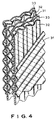
- the individual packs are formed of three sets of sheets, as illustrated in Figure 3.
- the third set of sheets 33 is corrugated like sheets 31, but the sheets are arranged with the corrugations extending in an opposite direction but at the same or different angles from the corrugations of sheets 31.
- the three sets of sheets 31, 32 and 33 described above with respect to Figure 3 are arranged in the order illustrated in Figure 4, wherein sheet 31 is followed by the vertically corrugated sheet 32, which in turn is followed by the oppositely corrugated sheet 33 and then by another sheet 31.
- sheet 31 is followed by the vertically corrugated sheet 32, which in turn is followed by the oppositely corrugated sheet 33 and then by another sheet 31.
- a sheet 31 is in contact with and engages the sheet 33.
- This arrangement and relationship of the sheets with the additional interspersing of vertically corrugated sheets aids in reducing the tendency of clogging of the fill material.
- the angle of inclinations of the corrugations relative to the horizontal plane may he from 45° to 70° for the corrugations, or 20° to 45° from the vertical.
- the amplitudes or heights of the corrugations can be varied between the sheets.
- the sheets 31, 33 can have corrugations of the same amplitude while the vertically corrugated sheets 32 can have a greater amplitude. That amplitude can be varied as desired and may be twice that of sheets 31, 33.
- the enlarged passageways provided by this arrangement together with the vertical corrugations of sheets 32 will serve to prevent clogging.
- the vertically corrugated sheets may be formed of a greater length than the cross-corrugated sheets so that they extend beyond the bottom edges of the cross-corrugated sheets.
- the vertically corrugated sheets therefore will provide support for the pack or the fill layer below it.
- the vertically corrugated sheets will also provide a dewatering edge for the sheets with the slanted corrugations. This enhances the flushing action of the water at the interface between fill layers where clogging is likely to occur.
Landscapes
- Physics & Mathematics (AREA)
- Thermal Sciences (AREA)
- Engineering & Computer Science (AREA)
- Chemical & Material Sciences (AREA)
- Mechanical Engineering (AREA)
- General Engineering & Computer Science (AREA)
- Organic Chemistry (AREA)
- Chemical Kinetics & Catalysis (AREA)
- Physical Or Chemical Processes And Apparatus (AREA)
Claims (10)
- Gas-Flüssigkeits-Kontaktkörper (10) zur Verwendung in einer Gas-Flüssigkeits-Kontaktvorrichtung, der mindestens einen ersten und einen zweiten Satz von gewellten Lagen (31, 32) aufweist, wobei die Lagen (32) des ersten Satzes von Lagen (32) abwechselnd mit den Lagen (31) des zweiten Satzes angeordnet sind, sich die Wellungen im ersten Satz von Lagen (32) vertikal im Kontaktkörper (10) und die Wellungen im zweiten Satz unter einem Winkel zu den Wellungen des ersten Satzes erstrecken, um Kanäle zu bilden, die den Kontaktkörper (10) von Ende zu Ende durchdringen, und wobei sich die Wellungen der gewellten Lagen (31, 32) gegeneinander abstützen, so daß sich die Lagen (31, 32) berühren, wobei sich die Firstkämme ihrer entsprechenden Wellungen kreuzen.
- Gas-Flüssigkeits-Kontaktkörper nach Anspruch 1, bei dem die Wellungen der Lagen (31, 32) die gleiche Amplitude besitzen.
- Gas-Flüssigkeits-Kontaktkörper nach Anspruch 1, bei dem sich die Amplitude der Wellungen im ersten Satz von Lagen (32) von der Amplitude der Wellungen im zweiten Satz von Lagen (31) unterscheidet.
- Gas-Flüssigkeits-Kontaktkörper nach Anspruch 1, bei dem die Lagen (32) des ersten Satzes größer sind als die Lagen (31) des zweiten Satzes und sich unter die unteren Ränder der Lagen (31) des zweiten Satzes im Kontaktkörper (10) erstrecken.
- Gas-Flüssigkeits-Kontaktkörper nach Anspruch 1, der einen dritten Satz von gewellten Lagen (33) im Kontaktkörper (10) aufweist, wobei sich die Wellungen im dritten Satz unter einem Winkel zu den Wellungen im ersten Satz und in entgegengesetzter Richtung zu den Wellungen in den Lagen (31) des zweiten Satzes erstrecken und wobei die Lagen (32) im ersten Satz zwischen den Lagen (31, 33) des zweiten und dritten Satzes angeordnet sind.
- Gas-Flüssigkeits-Kontaktkörper nach Anspruch 5, bei dem die Neigungen der Wellungen des ersten und dritten Satzes nicht symmetrisch sind.
- Gas-Flüssigkeits-Kontaktkörper nach Anspruch 6, bei dem die Wellungen des ersten Satzes von Lagen (32) eine größere Neigung zur Horizontalebene besitzen als die Wellungen im dritten Satz von Lagen (33).
- Gas-Flüssigkeits-Kontaktkörper nach Anspruch 5, bei dem die Wellungen der Lagen (31, 32, 33) der drei Sätze die gleiche Amplitude besitzen.
- Gas-Flüssigkeits-Kontaktkörper nach Anspruch 5, bei dem die Amplitude der Wellungen im ersten und dritten Satz von Lagen (32, 33) gegenüber der Amplitude der Wellungen im zweiten Satz von Lagen (32) unterschiedlich ist.
- Gas-Flüssigkeits-Kontaktkörper nach Anspruch 5, bei dem die Lagen (31) des zweiten Satz breiter sind als die Lagen des ersten und dritten Satzes (32, 33) und sich unter die Bodenränder der Lagen (32, 33) im ersten und zweiten Satz erstrecken.
Applications Claiming Priority (2)
| Application Number | Priority Date | Filing Date | Title |
|---|---|---|---|
| US07/941,247 US5242627A (en) | 1992-09-04 | 1992-09-04 | Contact bodies for liquid and gas |
| US941247 | 2001-08-28 |
Publications (2)
| Publication Number | Publication Date |
|---|---|
| EP0585550A1 EP0585550A1 (de) | 1994-03-09 |
| EP0585550B1 true EP0585550B1 (de) | 1997-08-06 |
Family
ID=25476168
Family Applications (1)
| Application Number | Title | Priority Date | Filing Date |
|---|---|---|---|
| EP93109500A Expired - Lifetime EP0585550B1 (de) | 1992-09-04 | 1993-06-15 | Kontaktkörper für Flüssigkeiten und Gase |
Country Status (6)
| Country | Link |
|---|---|
| US (1) | US5242627A (de) |
| EP (1) | EP0585550B1 (de) |
| AR (1) | AR247626A1 (de) |
| DE (1) | DE69312824T2 (de) |
| ES (1) | ES2107585T3 (de) |
| MX (1) | MX9304904A (de) |
Families Citing this family (15)
| Publication number | Priority date | Publication date | Assignee | Title |
|---|---|---|---|---|
| US5540867A (en) * | 1993-11-18 | 1996-07-30 | Munters Corporation | Hanger-supported liquid-gas contact body and assembly method |
| RU2184606C2 (ru) * | 2000-01-17 | 2002-07-10 | Пильч Леонид Моисеевич | Блок структурированной насадки для тепломассообменных аппаратов |
| US6385987B2 (en) | 2000-02-23 | 2002-05-14 | Leslie Schlom | Heat exchanger for cooling and for a pre-cooler for turbine intake air conditioning |
| RU2195364C1 (ru) * | 2001-09-12 | 2002-12-27 | Жестков Сергей Васильевич | Насадка вертикального прямоточного реактора |
| US8637512B2 (en) * | 2002-07-29 | 2014-01-28 | Glaxo Group Limited | Formulations and method of treatment |
| AU2002366957A1 (en) * | 2002-12-24 | 2004-07-22 | Vladimir Mikhailovich Kosyrev | Nozzle for a vertical once-through reactor |
| US20050051916A1 (en) * | 2003-09-08 | 2005-03-10 | C.E. Shepherd Co., Inc. | Cooling media pack |
| US7105036B2 (en) * | 2003-12-08 | 2006-09-12 | C. E. Shepherd Co., Inc. | Drift eliminator, light trap, and method of forming same |
| US7765827B2 (en) * | 2005-11-08 | 2010-08-03 | Everest Acquisition Holdings, Inc. | Multi-stage hybrid evaporative cooling system |
| US9310141B2 (en) | 2011-06-22 | 2016-04-12 | Gerald William Niebur | Counter current heat exchange module |
| EP2881694B1 (de) | 2013-12-06 | 2019-02-20 | Hewitech GmbH & Co. KG | Einbaueinrichtung für eine Vorrichtung zur Behandlung eines strömenden Fluids |
| US10495391B2 (en) * | 2016-05-26 | 2019-12-03 | Spx Cooling Technologies, Inc. | Flume apparatus and method for modular heat exchange tower |
| US10254057B2 (en) * | 2016-05-26 | 2019-04-09 | Spx Cooling Technologies, Inc. | Suction hood flume apparatus and method for modular heat exchange tower |
| US11293705B2 (en) | 2018-11-21 | 2022-04-05 | Brentwood Industries, Inc. | Open mesh members and related fill packs |
| PL3887032T3 (pl) | 2018-11-27 | 2024-03-25 | Brentwood Industries, Inc. | Pakiet wypełniający do wstawienia do wieży chłodniczej |
Family Cites Families (13)
| Publication number | Priority date | Publication date | Assignee | Title |
|---|---|---|---|---|
| US1823269A (en) * | 1929-06-10 | 1931-09-15 | Brassert & Co | Gas washer |
| DE1058077B (de) * | 1955-08-18 | 1959-05-27 | Hans Reichenbaecher Dr Ing | Kuehlturm mit grossflaechigen Rieseleinbauten |
| SE307963B (de) * | 1962-06-27 | 1969-01-27 | Munters C | |
| SE302778B (de) * | 1963-07-04 | 1968-08-05 | C Munters | |
| SE338333B (de) * | 1970-03-26 | 1971-09-06 | C Munters Ab | |
| US3785914A (en) * | 1971-07-08 | 1974-01-15 | H King | Structural material and means and method for making it |
| US3801419A (en) * | 1971-07-20 | 1974-04-02 | Munters Ab Carl | Corrugated sheet member with a reinforcing edge extending lengthwise of the corrugations |
| CH619202A5 (de) * | 1976-06-17 | 1980-09-15 | Sulzer Ag | |
| SE418646B (sv) * | 1976-09-29 | 1981-06-15 | Svenska Flaektfabriken Ab | Kontaktkropp for vetska och gas |
| SE420764B (sv) * | 1977-09-22 | 1981-10-26 | Munters Ab Carl | Anordning vid en evaporativ kylare |
| CH653908A5 (de) * | 1980-10-13 | 1986-01-31 | Jan Grochol | Rieselkoerper fuer stoff- und waermeaustausch. |
| US5013492A (en) * | 1990-04-06 | 1991-05-07 | Munters Corporation | Arrangement for contact bodies for liquid and gas |
| US5143658A (en) * | 1991-09-23 | 1992-09-01 | Munters Corporation | Alternating sheet evaporative cooling pad |
-
1992
- 1992-09-04 US US07/941,247 patent/US5242627A/en not_active Expired - Fee Related
-
1993
- 1993-06-15 EP EP93109500A patent/EP0585550B1/de not_active Expired - Lifetime
- 1993-06-15 DE DE69312824T patent/DE69312824T2/de not_active Expired - Lifetime
- 1993-06-15 ES ES93109500T patent/ES2107585T3/es not_active Expired - Lifetime
- 1993-08-11 AR AR93325668A patent/AR247626A1/es active
- 1993-08-12 MX MX9304904A patent/MX9304904A/es not_active IP Right Cessation
Also Published As
| Publication number | Publication date |
|---|---|
| EP0585550A1 (de) | 1994-03-09 |
| DE69312824T2 (de) | 1998-02-26 |
| DE69312824D1 (de) | 1997-09-11 |
| ES2107585T3 (es) | 1997-12-01 |
| MX9304904A (es) | 1994-03-31 |
| US5242627A (en) | 1993-09-07 |
| AR247626A1 (es) | 1995-01-31 |
Similar Documents
| Publication | Publication Date | Title |
|---|---|---|
| EP0585550B1 (de) | Kontaktkörper für Flüssigkeiten und Gase | |
| US5143658A (en) | Alternating sheet evaporative cooling pad | |
| US3792841A (en) | Liquid and gas contact apparatus | |
| US3917764A (en) | Sloped film fill assembly cooling tower | |
| EP1004838B1 (de) | Füllkörper mit Filmströmung, mit Gaswirbelströmung für Kontaktvorrichtung mit Stoff- und Wärmeaustausch, mit Rieselplatten mit Distanzstücken | |
| CA1241268A (en) | Serpentine film fill packing for evaporative heat and mass exchange | |
| US3450393A (en) | Gas and liquid contact apparatus | |
| EP0293003B1 (de) | Füllmaterial für Austauschkolonne | |
| KR0166104B1 (ko) | 주름판 조립체 | |
| US3947532A (en) | Liquid distribution strip | |
| EP0807462A1 (de) | Strukturierte Packungselement mit texturierter Oberfläche in zwei Richtungen sowie Masse- und Wärmeaustauschverfahren unter Verwendung desselben | |
| US4304738A (en) | Packing Material and apparatus | |
| JPS63151331A (ja) | 構造化塔充填物 | |
| US3983190A (en) | Liquid-gas contact apparatus and method for making the same | |
| US5013492A (en) | Arrangement for contact bodies for liquid and gas | |
| US5312464A (en) | Cross-flow film fill media with drift eliminator | |
| US5454988A (en) | Packing to be used in substance and/or heat exchanging tower | |
| KR19980071277A (ko) | 용량이 증진되고 질량 이동 효율이 높은 패킹 | |
| US5089137A (en) | Gas-liquid contact sheet and packing material | |
| CN1327182C (zh) | 具有冷却流体的热交换和物质交换装置的流体吸收栅板 | |
| EP0492802B1 (de) | Kolonnenpackung mit Leitvorrichtungen | |
| US4310475A (en) | Tower packing assembly | |
| US4385011A (en) | Sloped film fill assembly | |
| RU2008607C1 (ru) | Элемент оросителя противоточной градирни и блок оросителя противоточной градирни /варианты/ | |
| JP3184922B2 (ja) | 物質及び/又は熱交換塔用の充填材 |
Legal Events
| Date | Code | Title | Description |
|---|---|---|---|
| PUAI | Public reference made under article 153(3) epc to a published international application that has entered the european phase |
Free format text: ORIGINAL CODE: 0009012 |
|
| AK | Designated contracting states |
Kind code of ref document: A1 Designated state(s): DE ES FR GB IT SE |
|
| 17P | Request for examination filed |
Effective date: 19940519 |
|
| 17Q | First examination report despatched |
Effective date: 19960325 |
|
| GRAG | Despatch of communication of intention to grant |
Free format text: ORIGINAL CODE: EPIDOS AGRA |
|
| GRAH | Despatch of communication of intention to grant a patent |
Free format text: ORIGINAL CODE: EPIDOS IGRA |
|
| GRAH | Despatch of communication of intention to grant a patent |
Free format text: ORIGINAL CODE: EPIDOS IGRA |
|
| GRAA | (expected) grant |
Free format text: ORIGINAL CODE: 0009210 |
|
| AK | Designated contracting states |
Kind code of ref document: B1 Designated state(s): DE ES FR GB IT SE |
|
| REF | Corresponds to: |
Ref document number: 69312824 Country of ref document: DE Date of ref document: 19970911 |
|
| ITF | It: translation for a ep patent filed | ||
| REG | Reference to a national code |
Ref country code: ES Ref legal event code: FG2A Ref document number: 2107585 Country of ref document: ES Kind code of ref document: T3 |
|
| ET | Fr: translation filed | ||
| PLBE | No opposition filed within time limit |
Free format text: ORIGINAL CODE: 0009261 |
|
| STAA | Information on the status of an ep patent application or granted ep patent |
Free format text: STATUS: NO OPPOSITION FILED WITHIN TIME LIMIT |
|
| 26N | No opposition filed | ||
| REG | Reference to a national code |
Ref country code: GB Ref legal event code: IF02 |
|
| PGFP | Annual fee paid to national office [announced via postgrant information from national office to epo] |
Ref country code: SE Payment date: 20070618 Year of fee payment: 15 |
|
| EUG | Se: european patent has lapsed | ||
| REG | Reference to a national code |
Ref country code: GB Ref legal event code: 732E Free format text: REGISTERED BETWEEN 20090219 AND 20090225 |
|
| PG25 | Lapsed in a contracting state [announced via postgrant information from national office to epo] |
Ref country code: SE Free format text: LAPSE BECAUSE OF NON-PAYMENT OF DUE FEES Effective date: 20080616 |
|
| PGFP | Annual fee paid to national office [announced via postgrant information from national office to epo] |
Ref country code: GB Payment date: 20120613 Year of fee payment: 20 |
|
| PGFP | Annual fee paid to national office [announced via postgrant information from national office to epo] |
Ref country code: IT Payment date: 20120626 Year of fee payment: 20 |
|
| PGFP | Annual fee paid to national office [announced via postgrant information from national office to epo] |
Ref country code: DE Payment date: 20120627 Year of fee payment: 20 Ref country code: ES Payment date: 20120618 Year of fee payment: 20 Ref country code: FR Payment date: 20120717 Year of fee payment: 20 |
|
| REG | Reference to a national code |
Ref country code: DE Ref legal event code: R071 Ref document number: 69312824 Country of ref document: DE |
|
| REG | Reference to a national code |
Ref country code: DE Ref legal event code: R071 Ref document number: 69312824 Country of ref document: DE |
|
| REG | Reference to a national code |
Ref country code: GB Ref legal event code: PE20 Expiry date: 20130614 |
|
| PG25 | Lapsed in a contracting state [announced via postgrant information from national office to epo] |
Ref country code: GB Free format text: LAPSE BECAUSE OF EXPIRATION OF PROTECTION Effective date: 20130614 Ref country code: DE Free format text: LAPSE BECAUSE OF EXPIRATION OF PROTECTION Effective date: 20130618 |
|
| REG | Reference to a national code |
Ref country code: ES Ref legal event code: FD2A Effective date: 20130828 |
|
| PG25 | Lapsed in a contracting state [announced via postgrant information from national office to epo] |
Ref country code: ES Free format text: LAPSE BECAUSE OF EXPIRATION OF PROTECTION Effective date: 20130616 |