EP0585446B1 - Low pressure mercury vapor discharge lamp containing an amalgam - Google Patents
Low pressure mercury vapor discharge lamp containing an amalgam Download PDFInfo
- Publication number
- EP0585446B1 EP0585446B1 EP93908141A EP93908141A EP0585446B1 EP 0585446 B1 EP0585446 B1 EP 0585446B1 EP 93908141 A EP93908141 A EP 93908141A EP 93908141 A EP93908141 A EP 93908141A EP 0585446 B1 EP0585446 B1 EP 0585446B1
- Authority
- EP
- European Patent Office
- Prior art keywords
- lamp
- amalgam
- container
- tubulation
- mercury vapor
- Prior art date
- Legal status (The legal status is an assumption and is not a legal conclusion. Google has not performed a legal analysis and makes no representation as to the accuracy of the status listed.)
- Expired - Lifetime
Links
Images

Classifications
-
- H—ELECTRICITY
- H01—ELECTRIC ELEMENTS
- H01J—ELECTRIC DISCHARGE TUBES OR DISCHARGE LAMPS
- H01J61/00—Gas-discharge or vapour-discharge lamps
- H01J61/02—Details
- H01J61/30—Vessels; Containers
- H01J61/32—Special longitudinal shape, e.g. for advertising purposes
- H01J61/327—"Compact"-lamps, i.e. lamps having a folded discharge path
-
- H—ELECTRICITY
- H01—ELECTRIC ELEMENTS
- H01J—ELECTRIC DISCHARGE TUBES OR DISCHARGE LAMPS
- H01J61/00—Gas-discharge or vapour-discharge lamps
- H01J61/02—Details
- H01J61/24—Means for obtaining or maintaining the desired pressure within the vessel
-
- H—ELECTRICITY
- H01—ELECTRIC ELEMENTS
- H01J—ELECTRIC DISCHARGE TUBES OR DISCHARGE LAMPS
- H01J61/00—Gas-discharge or vapour-discharge lamps
- H01J61/02—Details
- H01J61/30—Vessels; Containers
- H01J61/305—Flat vessels or containers
- H01J61/307—Flat vessels or containers with folded elongated discharge path
Definitions
- This invention relates in general to a low pressure mercury vapor discharge lamp containing an amalgam and pertains, more particularly, to the retention of the amalgam in the lamp such that it regulates the mercury vapor pressure and permits the lamp to be operated efficiently and with high lumens output.
- the mercury vapor density or mercury vapor pressure in fluorescent lamps is an important parameter in determining lumen output and lamp efficacy.
- Low-pressure mercury vapor discharge lamps have a maximum efficiency of converting the electrical energy supplied into ultraviolet radiation at a predetermined vapor pressure. It is known that the envelope cold spot temperature for most efficient lamp operation is approximately 40°C. This temperature causes a mercury vapor pressure of approximately 4 to 6X10 -3 Torr to occur inside the lamp.
- the mercury vapor pressure is typically very highly dependent on the temperature of operation of the lamp. Often, due to high lamp loading or high ambient temperature, the envelope temperature and mercury vapor pressure rise above the optimum value. As the temperature of lamp operation increases, the vapor pressure and density of mercury in the discharge lamp tend to increase above the desired levels required for optimum light output and efficiency of operation.
- the location of the amalgam in the lamp is an important fact in providing the desired improvement.
- the lamp temperature can vary significantly relative to the desired stabilization of the lamp.
- the location of the alloy will effect its temperature and, in turn, the mercury vapor pressure.
- J. Bloem et al. "Amalgams for Fluorescent Lamps", Philips Tech. Rev., 38, 83-88 (1978) suggests that the location of amalgams can be important for lamp starting if the heat from the filament can be coupled to the amalgam.
- U.S. patents 4,977,349 to Asakura et al, and 4,288,715 to van Overveld et al, as well as U.K. application 2,157,883 describe compact type low-pressure mercury vapor discharge lamps having a folded path between the electrodes which employ an amalgam in the electrode stem area.
- a restriction in a receptacle aids in keeping the amalgam confined to the receptacle.
- amalgam has a tendency to fall into the lamp.
- the temperatures in the stem area may be undesirably high for the amalgam.
- U.S. patent 4,393,325 to van der Kooi describes a compact lamp with a build in ballast included in the lamp base and the amalgam positioned away from the stem area. The amalgam is in separate metal container having a slit opening to the arc discharge area.
- the amalgam is positioned at a particular location in a twin tube lamp which position is conducive to lamp manufacture and operation.
- lamps are typically processed with the base up utilizing cooling to maintain the alloy as a solid for retention purposes. For some manufacturing conditions, it is difficult to pool the alloy.
- the container retains the alloy even in its melted state during base up manufacturing.
- a pair of U-shaped tubes each include a pair of substantially parallel inner and outer legs.
- the respective inner and outer legs are connected at one end of the lamp by a transversely extending bridging section.
- the inner and outer legs are closed at the opposite end of the lamp.
- a connecting conduit joins respective inner legs for completing the discharge path between the electrode assemblies.
- a pair of electrodes are positioned at the respective closed ends of the outer legs and at least one of the closed ends of the inner legs including the tubulation.
- FIG. 1 illustrates a fluorescent lamp 11 which includes a folded elongated light-transmissive sealed envelope 13 having a generally circular cross section.
- a discharge assembly includes a pair of electrode assemblies 15,17.
- Each of the assemblies 15,17 include a pair of lead-in-wires 19,21 which are sealed in a stem mount.
- Each of the lead-in-wires 19,21 are connected to the respective ends of an electrode 25.
- the envelope 13, as finally assembled, is subjected to a vacuum and contains a conventional discharge sustaining fill which includes mercury.
- the inner surface of the elongated glass envelope 13 is coated with a phosphor powder.
- the compact fluorescent lamp 11 twin tube configuration as illustrated in FIG. 1 includes a pair of U-shaped tubes 29,31 joined by a connecting conduit 33 for completing the discharge path between the electrode assemblies 15,17.
- Each of the U-shaped tubes 29,31 includes a pair of legs 35,37 which are joined by a transverse bridging section 39.
- the legs 35,37 are substantial parallel alignment and in the same plane although other arrangements are contemplated.
- Respective inner legs 37 are joined to respective outer legs 35 at the bridging section 39 at one end of the lamp. At the opposite end of the lamp, the respective ends of the legs 35,37 are closed.
- the closed ends of the outer legs 35 include the electrodes while the closed ends of the inner legs are shown with tubulations 45 and 46.
- leg 35 is at an exterior portion of the lamp 11 and leg 37 is at an interior portion of the lamp 11.
- the respective interior legs as represented by 37 are connected by transversly extending conduit 33 at a position spaced from the closed ends.
- the end portions of the respective inner legs 37 include a tubulation 45.
- the tubulation 45 associated with tube 29 is preferably available for exhausting the interior of the lamp envelope and adding fill during lamp manufacture.
- the tubulation associated with the other inner tube 37 includes the container and amalgam as shown in detail in Fig. 2.
- the envelope is typically heated to release water absorbed on the inside surfaces.
- the chemicals may be introduced prior to removal of the tubulation.
- the tubulation 45 communicates with the envelope 13 for exhausting air and other gas from the envelope and introducing desirable fill ingredients into the envelope 13.
- the tubulation 45 is shown in the drawing as being tipped off but it also may be removed. Note that the above steps may be performed after the amalgam 49 and container 51 have been positioned in tubulation 46.
- FIG. 2A illustrates the manufacturing steps for incorporating the container 51 and amalgam 49 in the tubulation 46 in detail. Due to the technique of forming the tubulation 46, the tubulation 46 has a restriction 47 at the junction with the envelope 13. The details of manufacture as set forth in FIG. 2 are described in more detail in subsequent description.
- the compact low pressure and normally low temperature mercury vapor discharge lamp 11 of the type includes an amalgam 49 which is sufficiently exposed for contacting the gaseous discharge ingredients.
- the term amalgam is used to refer to a material which is capable of absorbing mercury vapor from the lamp volume.
- the amalgam is a metal alloy such as an alloy containing bismuth and indium. Such an alloy is generally ductile at temperatures of about 100°C and may become liquid at higher lamp operating temperatures.
- the purpose of the amalgam 49 is to stabilize the mercury vapor pressure at relatively high operating temperatures at which the mercury vapor pressure undesirable increases.
- the amalgam 49 is not directly in the discharge space but is accessible to the discharge space.
- the lamp comprises a sealed glass envelope having disposed therein ingredients comprising a rare gas and mercury for forming an electric discharge sustaining gas within said interior.
- a pair of electrodes are mounted in sealing relationship with said glass envelope and adapted for generating an electrical discharge extends through said arc sustaining gas.
- the discharge path extents from electrode assembly 15, down and around U-shaped tube 31, through the connecting conduit 33, down leg 37, through bridging section 39, and and up leg 35 of U-shaped tube 29.
- the tubulation 46 containing the amalgam is spaced from the discharge path so that the temperature in the tubulation 46 remains relatively low during normal operation of the lamp 11 and the mercury absorbing properties of the amalgam 46 are not fully utilized.
- the tubulation 46 is positioned at a normally lower temperature location spaced from the electrodes and discharge areas 15 and 17.
- the tubulation 46 is also positioned away from the direct path of the the discharge.
- the tubulation 46 has one end in communication with the arc sustaining gas through the restriction 47.
- the purpose of the amalgam is to control the mercury vapor pressure in the lamp through its mercury absorbing properties.
- a typical mercury dose of 10 mg or 5X10 -5 moles implies an indium mass of 78 mg. This is in the range of ratios of Hg to indium used in practice.
- temperatures are high enough so that the amalgam begins to melt the mercury vapor pressure variation with increasing temperature can reach a stabilized region.
- P m P o 2.2T m /14,660
- Preferred amalgams include a metal alloy containing bismuth and indium and a metal alloy containing bismuth, tin, and lead.
- FIG. 2 illustrates the method of manufacture of the lamp 11 of the present invention incorporating amalgam 49 in a manner so as retain the amalgam 49 in the tubulation 49 even when the amalgam 49 is liquified.
- the amalgam 49 is retained in a container 51.
- a solid body of the amalgam 49 is placed in the cup-shaped container 51.
- the container 51 was of a Nicromet 426 material having a hight of 5.08 mm (0.200 inch), a diameter of 2.159 mm (0.085 inch), and a wall thickness of 0,076 mm (0.003 inch).
- the container 51 as illustrated in the drawing is closed at the bottom and open at the top.
- the container 51 may include wall perforations which increase the surface area of the amalgam 49 available for contacting the the discharge gas. During processing of the lamp the openings can prevent outgassing. In this later case, it is contemplate that such perforations or openings are sufficiently small so that liquified amalgam 49 will be retained in the container 49 by surface tension.
- FIG. 2B illustrates a container 51 holding the amalgam 49 which has an exterior shape conforming to the interior shape of the container 51.
- the container 51 is inserted into the open end of the tubulation 45.
- the restriction 47 is less than the diameter of the container 51 so that the container is retained in the tubulation 45 and cannot pass into the main discharge area of the lamp 11.
- the diameter of the tubulation 45 is larger than the container 51 so that the container 51 is loosely or moveable held in the tubulation so that discharge gases are free to communicate with the amalgam 49 around the container 51.
- the tubulation 45 had an inside diameter of about 2.54 mm (0.10 inch).
- the exposed or open end 55 of the tubulation 46 is sealed or tipped off by melting the glass.
- the resulting tubulation 46 has one closed end, a restriction 47 at the other end, and container 51 holding the amalgam 49 confined within the tubulation 46.
- the restriction 47 is sufficiently narrow so as to stop the movement of the container 51.
- the contacting between the container 51 and the restriction 47 should enable discharge gas to flow through the restriction 47 so as to contact an exposed surface of the amalgam 49 during lamp 11 operation.
- the height of the closed tubulation 46 as measured from the restriction was about 8.89 mm (0.350 inch). Thus, a small space was provided above the container 51 for the container 51 to float or move.
Landscapes
- Discharge Lamp (AREA)
- Vessels And Coating Films For Discharge Lamps (AREA)
Abstract
Description
- This invention relates in general to a low pressure mercury vapor discharge lamp containing an amalgam and pertains, more particularly, to the retention of the amalgam in the lamp such that it regulates the mercury vapor pressure and permits the lamp to be operated efficiently and with high lumens output.
- The mercury vapor density or mercury vapor pressure in fluorescent lamps is an important parameter in determining lumen output and lamp efficacy. Low-pressure mercury vapor discharge lamps have a maximum efficiency of converting the electrical energy supplied into ultraviolet radiation at a predetermined vapor pressure. It is known that the envelope cold spot temperature for most efficient lamp operation is approximately 40°C. This temperature causes a mercury vapor pressure of approximately 4 to 6X10⁻³Torr to occur inside the lamp.
- The mercury vapor pressure is typically very highly dependent on the temperature of operation of the lamp. Often, due to high lamp loading or high ambient temperature, the envelope temperature and mercury vapor pressure rise above the optimum value. As the temperature of lamp operation increases, the vapor pressure and density of mercury in the discharge lamp tend to increase above the desired levels required for optimum light output and efficiency of operation.
- It is well known to control the mercury vapor pressure by use of an metal or metal alloy which forms an amalgam with mercury. As the mercury vapor pressure increases to an undesirable level, the amalgam begins to melt and form a solution with mercury vapor so as to decrease the vapor pressure of the mercury and return the lamp to a more optimal operation. Amalgams of indium and bismuth are known to possess these desirable properties. Such a low pressure mercury vapor discharge lamp is known from GB-A-2 203 283.
- It is also known that the location of the amalgam in the lamp is an important fact in providing the desired improvement. In practice, the lamp temperature can vary significantly relative to the desired stabilization of the lamp. Thus, the location of the alloy will effect its temperature and, in turn, the mercury vapor pressure. J. Bloem et al., "Amalgams for Fluorescent Lamps", Philips Tech. Rev., 38, 83-88 (1978) suggests that the location of amalgams can be important for lamp starting if the heat from the filament can be coupled to the amalgam. U.S. patents 3,869,772 to Latassa et al, U.S. patent 3,898,720 to Morehead, and 4,157,485 to Wesselink et al describe the glass stem as a desirable location for the amalgam which may be alloys of indium, bismuth, and tin. British Patent Specification 1,097,090 to Sylvania discloses positioning amalgam at certain locations in fluorescent lamps.
- U.S. patents 4,977,349 to Asakura et al, and 4,288,715 to van Overveld et al, as well as U.K. application 2,157,883 describe compact type low-pressure mercury vapor discharge lamps having a folded path between the electrodes which employ an amalgam in the electrode stem area. In the '349 patent, a restriction in a receptacle aids in keeping the amalgam confined to the receptacle. However, during base up lamp processing amalgam has a tendency to fall into the lamp. When the ballast is included in the lamp base, the temperatures in the stem area may be undesirably high for the amalgam. U.S. patent 4,393,325 to van der Kooi describes a compact lamp with a build in ballast included in the lamp base and the amalgam positioned away from the stem area. The amalgam is in separate metal container having a slit opening to the arc discharge area.
- Although the above-described amalgam containing low-pressure mercury vapor discharge lamps have been employed with varying degrees of success, it has been found that certain disadvantages do exist. It is difficult to contain the amalgam during lamp processing and lamp operation when the lamp base is in an upward position. It is also difficult to incorporate the amalgam into the lamp at a location which is responsive to temperature at which the desirable absorption properties of the amalgam are advantageously utilized.
- It is, therefore, an object of the present invention to obviate one or more of the disadvantages of the prior art.
- In accordance with the present invention, there is provided a compact low pressure mercury vapor discharge lamp as defined in claim 1.
- In accordance an embodiment of the present invention, the amalgam is positioned at a particular location in a twin tube lamp which position is conducive to lamp manufacture and operation. During lamp manufacture, lamps are typically processed with the base up utilizing cooling to maintain the alloy as a solid for retention purposes. For some manufacturing conditions, it is difficult to pool the alloy. In the present invention, the container retains the alloy even in its melted state during base up manufacturing.
- In a compact low pressure mercury vapor discharge lamp of a twin tube configuration, a pair of U-shaped tubes each include a pair of substantially parallel inner and outer legs. The respective inner and outer legs are connected at one end of the lamp by a transversely extending bridging section. The inner and outer legs are closed at the opposite end of the lamp. A connecting conduit joins respective inner legs for completing the discharge path between the electrode assemblies. A pair of electrodes are positioned at the respective closed ends of the outer legs and at least one of the closed ends of the inner legs including the tubulation.
- Additional objects and advantages of the invention will be set forth in the description which follows, and in part will become apparent to those skilled in the art upon examination of the following or may be learned by practice of the invention. The aforementioned objects and advantages of the invention may be realized and attained by means of the instrumentalities and combination particularly pointed out in the appended claims.
- The invention will become more readily apparent from the following exemplary description in connection with the accompanying drawings, wherein:
- FIG. 1 is a schematic drawing of a double twin tube compact fluorescent lamp having a tubulation;
- FIG. 2 illustrates a container holding amalgam in the tubulation;
- For a better understanding of the present invention, together with other and further objects, advantages and capabilities thereof, reference is made to the following disclosure and appended claims in connection with the above-described drawings.
- Referring to the drawings, FIG. 1 illustrates a fluorescent lamp 11 which includes a folded elongated light-transmissive sealed
envelope 13 having a generally circular cross section. A discharge assembly includes a pair ofelectrode assemblies 15,17. Each of theassemblies 15,17 include a pair of lead-in-wires 19,21 which are sealed in a stem mount. Each of the lead-in-wires 19,21 are connected to the respective ends of anelectrode 25. Theenvelope 13, as finally assembled, is subjected to a vacuum and contains a conventional discharge sustaining fill which includes mercury. The inner surface of theelongated glass envelope 13 is coated with a phosphor powder. - The compact fluorescent lamp 11 twin tube configuration as illustrated in FIG. 1 includes a pair of
U-shaped tubes 29,31 joined by a connectingconduit 33 for completing the discharge path between theelectrode assemblies 15,17. Each of the U-shapedtubes 29,31 includes a pair oflegs transverse bridging section 39. Thelegs inner legs 37 are joined to respectiveouter legs 35 at thebridging section 39 at one end of the lamp. At the opposite end of the lamp, the respective ends of thelegs outer legs 35 include the electrodes while the closed ends of the inner legs are shown withtubulations - In terms of the overall assembly of the fluorescent lamp 11,
leg 35 is at an exterior portion of the lamp 11 andleg 37 is at an interior portion of the lamp 11. The respective interior legs as represented by 37 are connected by transversly extendingconduit 33 at a position spaced from the closed ends. The end portions of the respectiveinner legs 37 include atubulation 45. As illustrated in FIG. 1, thetubulation 45 associated withtube 29 is preferably available for exhausting the interior of the lamp envelope and adding fill during lamp manufacture. The tubulation associated with the otherinner tube 37 includes the container and amalgam as shown in detail in Fig. 2. - During the exhausting step, the envelope is typically heated to release water absorbed on the inside surfaces. During lamp manufacturing process, the chemicals may be introduced prior to removal of the tubulation. The
tubulation 45 communicates with theenvelope 13 for exhausting air and other gas from the envelope and introducing desirable fill ingredients into theenvelope 13. Thetubulation 45 is shown in the drawing as being tipped off but it also may be removed. Note that the above steps may be performed after theamalgam 49 andcontainer 51 have been positioned intubulation 46. - FIG. 2A illustrates the manufacturing steps for incorporating the
container 51 andamalgam 49 in thetubulation 46 in detail. Due to the technique of forming thetubulation 46, thetubulation 46 has arestriction 47 at the junction with theenvelope 13. The details of manufacture as set forth in FIG. 2 are described in more detail in subsequent description. - The compact low pressure and normally low temperature mercury vapor discharge lamp 11 of the type includes an
amalgam 49 which is sufficiently exposed for contacting the gaseous discharge ingredients. The term amalgam is used to refer to a material which is capable of absorbing mercury vapor from the lamp volume. Typically the amalgam is a metal alloy such as an alloy containing bismuth and indium. Such an alloy is generally ductile at temperatures of about 100°C and may become liquid at higher lamp operating temperatures. The purpose of theamalgam 49 is to stabilize the mercury vapor pressure at relatively high operating temperatures at which the mercury vapor pressure undesirable increases. - The
amalgam 49 is not directly in the discharge space but is accessible to the discharge space. The lamp comprises a sealed glass envelope having disposed therein ingredients comprising a rare gas and mercury for forming an electric discharge sustaining gas within said interior. A pair of electrodes are mounted in sealing relationship with said glass envelope and adapted for generating an electrical discharge extends through said arc sustaining gas. As illustrated in FIG. 1, the discharge path extents from electrode assembly 15, down and around U-shaped tube 31, through the connectingconduit 33, downleg 37, through bridgingsection 39, and and upleg 35 ofU-shaped tube 29. Thetubulation 46 containing the amalgam is spaced from the discharge path so that the temperature in thetubulation 46 remains relatively low during normal operation of the lamp 11 and the mercury absorbing properties of theamalgam 46 are not fully utilized. - The
tubulation 46 is positioned at a normally lower temperature location spaced from the electrodes anddischarge areas 15 and 17. Thetubulation 46 is also positioned away from the direct path of the the discharge. Thetubulation 46 has one end in communication with the arc sustaining gas through therestriction 47. - The purpose of the amalgam is to control the mercury vapor pressure in the lamp through its mercury absorbing properties. Intuitively, one can consider the analogy of an ideal solution to the mercury-alloy system. In the ideal case the vapor pressure of the component under consideration is reduced in proportion to the mole fraction of the component in solution,

- P=Hg vapor pressure over solution
- Po=pure Hg vapor pressure at given temperature
- XA=Hg mole fraction in solution = mHg/(mHg + mAlloy)
- mHg=moles of Hg in solution
- mAlloy=moles of solvent
- Assume that the desired mercury vapor pressure is 0.8 Pa (6X10⁻³ Torr), corresponding to a control point temperature of 40°C. It is not uncommon for compact fluorescent lamps running in recessed fixtures to reach control point temperatures of 80°C. This corresponds to a mercury vapor pressure of 11.7 Pa (88X10-3 Torr). Based on the above ideal solution equation the required mole fraction of Hg to reduce the mercury vapor pressure from 88 mTorr to 6 mTorr would be

- As a specific example consider the In-Hg amalgam. Assume an ideal solution. The corresponding mole ratio of Hg to indium would be

- A typical mercury dose of 10 mg or 5X10⁻⁵ moles implies an indium mass of 78 mg. This is in the range of ratios of Hg to indium used in practice. When temperatures are high enough so that the amalgam begins to melt the mercury vapor pressure variation with increasing temperature can reach a stabilized region. As discussed in reference J. Bloem et al., "Some New Mercury Alloys for Use in Fluorescent Lamps"' J. of IES, 141, April, (1977), this occurs such that the maximum vapor pressure in the stable region is given as (ideal solution approximation)
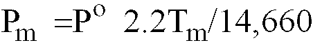
- Pm=maximum mercury vapor pressure in stabilized region
- Tm=melting point temperature of alloy
- Since Hg and alloys form solutions with are not ideal departures from the above ideal solution case are expected. A more general treatment of the vapor pressure above a solution can be obtained by considering the vapor pressure to be given as

- g=activity coefficient (1 for an ideal solution)
- This is discussed in more detail in the reference set forth above. As an estimate the ideal solution expression for Pm required for 80°C control spot can be readily obtained. Since


- Preferred amalgams include a metal alloy containing bismuth and indium and a metal alloy containing bismuth, tin, and lead.
- FIG. 2 illustrates the method of manufacture of the lamp 11 of the present
invention incorporating amalgam 49 in a manner so as retain theamalgam 49 in thetubulation 49 even when theamalgam 49 is liquified. In a accordance with the principles of the present invention, theamalgam 49 is retained in acontainer 51. As illustrated in FIG. 2A, a solid body of theamalgam 49 is placed in the cup-shapedcontainer 51. In one embodiment, thecontainer 51 was of a Nicromet 426 material having a hight of 5.08 mm (0.200 inch), a diameter of 2.159 mm (0.085 inch), and a wall thickness of 0,076 mm (0.003 inch). Thecontainer 51 as illustrated in the drawing is closed at the bottom and open at the top. It is contemplated that thecontainer 51 may include wall perforations which increase the surface area of theamalgam 49 available for contacting the the discharge gas. During processing of the lamp the openings can prevent outgassing. In this later case, it is contemplate that such perforations or openings are sufficiently small so that liquifiedamalgam 49 will be retained in thecontainer 49 by surface tension. - Next the container and amalgam are heated to melt the
amalgam 49 so that it conforms to the shape of the container. FIG. 2B illustrates acontainer 51 holding theamalgam 49 which has an exterior shape conforming to the interior shape of thecontainer 51. As illustrated in FIG 2C, thecontainer 51 is inserted into the open end of thetubulation 45. Therestriction 47 is less than the diameter of thecontainer 51 so that the container is retained in thetubulation 45 and cannot pass into the main discharge area of the lamp 11. The diameter of thetubulation 45 is larger than thecontainer 51 so that thecontainer 51 is loosely or moveable held in the tubulation so that discharge gases are free to communicate with theamalgam 49 around thecontainer 51. In the embodiment utilizing the above mentionedcontainer 51, thetubulation 45 had an inside diameter of about 2.54 mm (0.10 inch). - As illustrated in FIG. 2D, the exposed or
open end 55 of thetubulation 46 is sealed or tipped off by melting the glass. The resultingtubulation 46 has one closed end, arestriction 47 at the other end, andcontainer 51 holding theamalgam 49 confined within thetubulation 46. Thus, when the lamp 11 is mounted with base or the electrode assembles 15,17 up, thecontainer 51 retainsamalgam 49 even if it is a liquid. This position is illustrated in detail in FIG. 2D. It is contemplated that therestriction 47 is sufficiently narrow so as to stop the movement of thecontainer 51. The contacting between thecontainer 51 and therestriction 47 should enable discharge gas to flow through therestriction 47 so as to contact an exposed surface of theamalgam 49 during lamp 11 operation. In the embodiment of the invention as described above, the height of theclosed tubulation 46 as measured from the restriction was about 8.89 mm (0.350 inch). Thus, a small space was provided above thecontainer 51 for thecontainer 51 to float or move. - While there have been shown and described what are at present considered to be the preferred embodiments of the invention, it will be apparent to those skilled in the art that various changes and modifications can be made herein without departing from the scope of the invention. Therefore, the aim in the appended claims is to cover all such changes and modifications as fall within the scope of the invention. The matter set forth in the foregoing description and accompanying drawings is offered by way of illustration only and not as a limitation. The actual scope of the invention is intended to be defined in the following claims.
Claims (10)
- A low pressure mercury vapor discharge lamp comprising a sealed glass envelope (29, 31, 33) having a fill material comprising mercury for sustaining an electric arc discharge, a pair of electrodes (25) sealed in said glass envelope and adapted for generating an electrical arc discharge, a tubulation (46) positioned at a location spaced from said electrodes, said tubulation having one end in communication with said fill material and the other end being closed, and an amalgam (49) for absorbing mercury vapor by contacting an exposed surface portion of the amalgam, characterised in that a container (51) is confined within said tubulation (46), which is adapted for retention of liguified amalgam (49) within said tubulation, and mercury vapor from said fill material is in communication with said amalgam.
- A lamp as claimed in claim 1 characterised in that said lamp comprises a twin tube configuration including a pair of U-shaped tubes (29, 31), each U-shaped tube includes an inner (37) and substantially parallel outer leg (35), said respective inner and outer legs being connected at one end of the lamp by a transversly extending bridging section (33), said inner and outer legs being closed at the opposite end of the lamp, said bridging section (33) connecting said respective inner legs for completing the discharge path between said pair of electrodes (25), said electrodes being positioned at the respective closed ends of said outer legs (35), and at least one of said closed ends of said inner legs (33) including said tubulation (46).
- A lamp as claimed in claims 1 or 2 characterised in that said amalgam is a metal alloy containing either bismuth and indium, or bismuth, tin and lead.
- A lamp as claimed in any of claims 1, 2 or 3 characterised in that said container (51) is closed at the bottom and open at the top.
- A lamp as claimed in any of the preceding claims characterised in that said container (51) is moveably held in the tubulation (46) so that the fill material is free to communicate with the amalgam (49) around said container.
- A lamp as claimed in any of the preceding claims characterised in that said container (51) includes wall perforations.
- A lamp as claimed in claim 6 characterised in that said perforations are sufficiently small that liguified amalgam (49) is retained in the container (51) by surface tension.
- A lamp as claimed in any of the preceding claims characterised in that said tubulation (46) has a restriction (47) to support said container (51).
- A lamp as claimed in claim 8 characterised in that said restriction (47) is less than the diameter of the container (51).
- A lamp as claimed in any of the preceding claims characterised in that said container (51) is supported in an open-end upwards position during lamp operation.
Applications Claiming Priority (3)
| Application Number | Priority Date | Filing Date | Title |
|---|---|---|---|
| US07/850,763 US5294867A (en) | 1992-03-13 | 1992-03-13 | Low pressure mercury vapor discharge lamp containing an amalgam |
| PCT/NL1993/000053 WO1993018542A1 (en) | 1992-03-13 | 1993-03-08 | Low pressure mercury vapor discharge lamp containing an amalgam |
| US850763 | 2001-05-08 |
Publications (2)
| Publication Number | Publication Date |
|---|---|
| EP0585446A1 EP0585446A1 (en) | 1994-03-09 |
| EP0585446B1 true EP0585446B1 (en) | 1996-06-26 |
Family
ID=25309049
Family Applications (1)
| Application Number | Title | Priority Date | Filing Date |
|---|---|---|---|
| EP93908141A Expired - Lifetime EP0585446B1 (en) | 1992-03-13 | 1993-03-08 | Low pressure mercury vapor discharge lamp containing an amalgam |
Country Status (5)
| Country | Link |
|---|---|
| US (1) | US5294867A (en) |
| EP (1) | EP0585446B1 (en) |
| CA (1) | CA2092601A1 (en) |
| DE (1) | DE69303336T2 (en) |
| WO (1) | WO1993018542A1 (en) |
Families Citing this family (24)
| Publication number | Priority date | Publication date | Assignee | Title |
|---|---|---|---|---|
| CA2112091A1 (en) * | 1992-12-22 | 1994-06-23 | Andre C. Bouchard | Apparatus for shortening stabilization time in high output compact fluorescent lamps |
| DE4314744A1 (en) * | 1993-05-04 | 1994-11-10 | Patent Treuhand Ges Fuer Elektrische Gluehlampen Mbh | Compact fluorescent lamp |
| TW344018B (en) * | 1994-07-15 | 1998-11-01 | Philips Electronics Nv | Low-pressure mercury vapor discharge lamp |
| DE19512129A1 (en) * | 1995-03-31 | 1996-10-02 | Patent Treuhand Ges Fuer Elektrische Gluehlampen Mbh | Low pressure mercury vapor discharge lamp |
| US5739633A (en) * | 1995-08-14 | 1998-04-14 | General Electric Company | Amalgam containing compact fluorescent lamp with improved warm-up |
| CA2177108C (en) * | 1996-05-22 | 2002-10-22 | Minoru Myojo | Low pressure mercury vapor filled discharge lamp |
| CN1090811C (en) * | 1996-06-05 | 2002-09-11 | 松下电器产业株式会社 | Low pressure mercury vapor filled discharge lamp |
| US6384478B1 (en) * | 1998-05-06 | 2002-05-07 | Conexant Systems, Inc. | Leadframe having a paddle with an isolated area |
| US6361864B1 (en) * | 1998-06-02 | 2002-03-26 | Osram Sylvania Inc. | Method for making high-efficacy and long life electroluminescent phophor |
| JP2000173537A (en) * | 1998-09-29 | 2000-06-23 | Toshiba Lighting & Technology Corp | Low pressure mercury-vapor discharge lamp and lighting system |
| US6456004B1 (en) * | 1999-09-10 | 2002-09-24 | General Electric Company | Fluorescent lamp having uniquely configured container containing amalgam for regulating mercury vapor equilibrium |
| US6630779B1 (en) * | 2000-06-01 | 2003-10-07 | General Electric Company | Fluorescent lamp with discharge tube bent substantially in plane |
| US6528953B1 (en) * | 2001-09-25 | 2003-03-04 | Osram Sylvania Inc. | Amalgam retainer |
| ATE389236T1 (en) * | 2002-08-22 | 2008-03-15 | Osram Sylvania Inc | AMALGAM CONTAINER FOR FLUORESCENT LAMP |
| CN2604000Y (en) * | 2003-03-11 | 2004-02-18 | 黄甜仔 | Spiral fluorescent tube |
| CN100444304C (en) * | 2003-03-11 | 2008-12-17 | 广州新阳照明电器有限公司 | Spiral fluorescent light tube |
| US7095167B2 (en) * | 2003-04-03 | 2006-08-22 | Light Sources, Inc. | Germicidal low pressure mercury vapor discharge lamp with amalgam location permitting high output |
| US7863816B2 (en) * | 2003-10-23 | 2011-01-04 | General Electric Company | Dielectric barrier discharge lamp |
| US7173254B2 (en) * | 2004-05-19 | 2007-02-06 | Light Sources, Inc. | Compact germicidal lamp having multiple wavelengths |
| JP4872224B2 (en) * | 2005-03-23 | 2012-02-08 | パナソニック電工株式会社 | Luminaire equipped with the same electrodeless discharge lamp |
| US8018130B2 (en) * | 2006-02-10 | 2011-09-13 | Koninklijke Philips Electronics N.V. | Low-pressure mercury vapor discharge lamp with amalgam |
| US20070216308A1 (en) * | 2006-03-16 | 2007-09-20 | Kiermaier Ludwig P | Lamp electrode and method for delivering mercury |
| US7625258B2 (en) * | 2006-03-16 | 2009-12-01 | E.G.L. Company Inc. | Lamp electrode and method for delivering mercury |
| DE102008021352A1 (en) * | 2008-04-29 | 2009-11-05 | Osram Gesellschaft mit beschränkter Haftung | Dosing container for receiving a mercury-containing material for a discharge lamp and method for producing such a dosing and discharge lamp with such a dosing and method for producing a discharge lamp |
Family Cites Families (15)
| Publication number | Priority date | Publication date | Assignee | Title |
|---|---|---|---|---|
| DE1133824B (en) * | 1960-09-05 | 1962-07-26 | Patra Patent Treuhand | Mercury low pressure discharge lamp for increased electrical and / or thermal load, especially fluorescent lamp |
| DE1937402U (en) * | 1964-12-31 | 1966-04-28 | Sylvania Electric Prod | FLUORESCENT LAMP. |
| US3898720A (en) * | 1972-09-28 | 1975-08-12 | Westinghouse Electric Corp | Method of providing a fluorescent lamp stem with an integral mercury-vapor pressure regulating means |
| US3869772A (en) * | 1974-04-25 | 1975-03-11 | Gte Sylvania Inc | Method of incorporating amalgam-forming material in a fluorescent lamp |
| NL168367C (en) * | 1975-06-20 | 1982-03-16 | Philips Nv | LOW-PRESSURE MERCURY DISCHARGE LAMP AND METHOD FOR THE PRODUCTION THEREOF. |
| NL177163C (en) * | 1976-03-04 | 1985-08-01 | Philips Nv | LOW-PRESSURE MERCURY DISCHARGE LAMP. |
| NL183687C (en) * | 1978-10-11 | 1988-12-16 | Philips Nv | LOW-PRESSURE MERCURY DISCHARGE LAMP. |
| US4528209A (en) * | 1978-10-25 | 1985-07-09 | General Electric Company | Use of amalgams in solenoidal electric field lamps |
| NL7906203A (en) * | 1979-08-15 | 1981-02-17 | Philips Nv | LOW-PRESSURE MERCURY DISCHARGE LAMP. |
| JPS59148258A (en) * | 1983-02-14 | 1984-08-24 | Mitsubishi Electric Corp | Mercury vapor discharge lamp |
| US4853591A (en) * | 1983-11-25 | 1989-08-01 | Patent Treuhand Gesellschaft Fur Elektrische Gluhlampen Mbh | Multiple-tube compact low-pressure discharge fluorescent lamp |
| NL8401030A (en) * | 1984-04-02 | 1985-11-01 | Philips Nv | LOW-PRESSURE MERCURY DISCHARGE LAMP. |
| JPH0746598B2 (en) * | 1986-05-29 | 1995-05-17 | 東芝ライテック株式会社 | Fluorescent lamp |
| US4835442A (en) * | 1987-01-29 | 1989-05-30 | Kabushiki Kaisha Toshiba | Lamp for generating ultraviolet radiation |
| JPH083997B2 (en) * | 1988-12-12 | 1996-01-17 | 東芝ライテック株式会社 | Low pressure mercury vapor discharge lamp |
-
1992
- 1992-03-13 US US07/850,763 patent/US5294867A/en not_active Expired - Fee Related
-
1993
- 1993-03-08 DE DE69303336T patent/DE69303336T2/en not_active Expired - Fee Related
- 1993-03-08 WO PCT/NL1993/000053 patent/WO1993018542A1/en active IP Right Grant
- 1993-03-08 EP EP93908141A patent/EP0585446B1/en not_active Expired - Lifetime
- 1993-03-12 CA CA002092601A patent/CA2092601A1/en not_active Abandoned
Also Published As
| Publication number | Publication date |
|---|---|
| WO1993018542A1 (en) | 1993-09-16 |
| EP0585446A1 (en) | 1994-03-09 |
| DE69303336D1 (en) | 1996-08-01 |
| DE69303336T2 (en) | 1997-02-20 |
| CA2092601A1 (en) | 1993-09-14 |
| US5294867A (en) | 1994-03-15 |
Similar Documents
| Publication | Publication Date | Title |
|---|---|---|
| EP0585446B1 (en) | Low pressure mercury vapor discharge lamp containing an amalgam | |
| US6337539B1 (en) | Low-pressure mercury vapor discharge lamp and illuminator | |
| US5841229A (en) | Amalgam support arrangement for an electrodeless discharge lamp | |
| CA1142212A (en) | Low pressure mercury vapour discharge lamp with pressure controlling amalgam in a container | |
| EP0646942B1 (en) | Accurate placement and retention of an amalgam in an electrodeless fluorescent lamp | |
| EP0758795B1 (en) | Amalgam containing compact fluorescent lamp | |
| US5783912A (en) | Electrodeless fluorescent lamp having feedthrough for direct connection to internal EMI shield and for supporting an amalgam | |
| JPS5981830A (en) | Metal halide arc discharge lamp with means for suppressing convection current in outside container and operating and assembling method therefor | |
| US4262231A (en) | Helical wire coil in solenoidal lamp tip-off region wetted by alloy forming an amalgam with mercury | |
| US5412289A (en) | Using a magnetic field to locate an amalgam in an electrodeless fluorescent lamp | |
| US4387319A (en) | Metal halide lamp containing ScI3 with added cadmium or zinc | |
| EP0719449B1 (en) | Low-pressure mercury vapour discharge lamp | |
| EP0667636B1 (en) | Fluorescent lamp | |
| US4757236A (en) | High pressure metal halide arc lamp with xenon buffer gas | |
| US5559392A (en) | Apparatus for securing an amalgam at the apex of an electrodeless fluorescent lamp | |
| US4528209A (en) | Use of amalgams in solenoidal electric field lamps | |
| US5327042A (en) | Metal halide lamp | |
| EP0183247A2 (en) | High pressure metal halide lamp with xenon buffer gas | |
| US20040056583A1 (en) | Fluorescent lamp and amalgam assembly therefor | |
| US4499400A (en) | Use of amalgams in solenoidal electric field lamps | |
| US4410829A (en) | Use of amalgams in solenoidal electric field lamps | |
| US20040041515A1 (en) | Fluorescent lamp and amalgam assembly therefor | |
| KR20040018149A (en) | Fluorescent lamp and amalgam assembly therefor | |
| JPH04280033A (en) | Manufacture of fluorescent lamp | |
| JPH01243339A (en) | Manufacture of fluorescent lamp |
Legal Events
| Date | Code | Title | Description |
|---|---|---|---|
| PUAI | Public reference made under article 153(3) epc to a published international application that has entered the european phase |
Free format text: ORIGINAL CODE: 0009012 |
|
| AK | Designated contracting states |
Kind code of ref document: A1 Designated state(s): BE DE FR GB NL |
|
| 17P | Request for examination filed |
Effective date: 19931220 |
|
| 17Q | First examination report despatched |
Effective date: 19950329 |
|
| GRAH | Despatch of communication of intention to grant a patent |
Free format text: ORIGINAL CODE: EPIDOS IGRA |
|
| GRAH | Despatch of communication of intention to grant a patent |
Free format text: ORIGINAL CODE: EPIDOS IGRA |
|
| GRAA | (expected) grant |
Free format text: ORIGINAL CODE: 0009210 |
|
| AK | Designated contracting states |
Kind code of ref document: B1 Designated state(s): BE DE FR GB NL |
|
| ET | Fr: translation filed | ||
| REF | Corresponds to: |
Ref document number: 69303336 Country of ref document: DE Date of ref document: 19960801 |
|
| PLBE | No opposition filed within time limit |
Free format text: ORIGINAL CODE: 0009261 |
|
| STAA | Information on the status of an ep patent application or granted ep patent |
Free format text: STATUS: NO OPPOSITION FILED WITHIN TIME LIMIT |
|
| 26N | No opposition filed | ||
| REG | Reference to a national code |
Ref country code: GB Ref legal event code: IF02 |
|
| PGFP | Annual fee paid to national office [announced via postgrant information from national office to epo] |
Ref country code: GB Payment date: 20020228 Year of fee payment: 10 Ref country code: BE Payment date: 20020228 Year of fee payment: 10 |
|
| PGFP | Annual fee paid to national office [announced via postgrant information from national office to epo] |
Ref country code: FR Payment date: 20020329 Year of fee payment: 10 |
|
| PGFP | Annual fee paid to national office [announced via postgrant information from national office to epo] |
Ref country code: NL Payment date: 20020331 Year of fee payment: 10 |
|
| PGFP | Annual fee paid to national office [announced via postgrant information from national office to epo] |
Ref country code: DE Payment date: 20020528 Year of fee payment: 10 |
|
| PG25 | Lapsed in a contracting state [announced via postgrant information from national office to epo] |
Ref country code: GB Free format text: LAPSE BECAUSE OF NON-PAYMENT OF DUE FEES Effective date: 20030308 |
|
| PG25 | Lapsed in a contracting state [announced via postgrant information from national office to epo] |
Ref country code: BE Free format text: LAPSE BECAUSE OF NON-PAYMENT OF DUE FEES Effective date: 20030331 |
|
| BERE | Be: lapsed |
Owner name: *FLOWIL INTERNATIONAL LIGHTING (HOLDING) B.V. Effective date: 20030331 |
|
| PG25 | Lapsed in a contracting state [announced via postgrant information from national office to epo] |
Ref country code: NL Free format text: LAPSE BECAUSE OF NON-PAYMENT OF DUE FEES Effective date: 20031001 Ref country code: DE Free format text: LAPSE BECAUSE OF NON-PAYMENT OF DUE FEES Effective date: 20031001 |
|
| GBPC | Gb: european patent ceased through non-payment of renewal fee |
Effective date: 20030308 |
|
| PG25 | Lapsed in a contracting state [announced via postgrant information from national office to epo] |
Ref country code: FR Free format text: LAPSE BECAUSE OF NON-PAYMENT OF DUE FEES Effective date: 20031127 |
|
| NLV4 | Nl: lapsed or anulled due to non-payment of the annual fee |
Effective date: 20031001 |
|
| REG | Reference to a national code |
Ref country code: FR Ref legal event code: ST |