EP0585175B1 - Dispositif et procédé pour mesurer le vieillissement d'un isolant composite polymère pour bobine de stator - Google Patents
Dispositif et procédé pour mesurer le vieillissement d'un isolant composite polymère pour bobine de stator Download PDFInfo
- Publication number
- EP0585175B1 EP0585175B1 EP19930402094 EP93402094A EP0585175B1 EP 0585175 B1 EP0585175 B1 EP 0585175B1 EP 19930402094 EP19930402094 EP 19930402094 EP 93402094 A EP93402094 A EP 93402094A EP 0585175 B1 EP0585175 B1 EP 0585175B1
- Authority
- EP
- European Patent Office
- Prior art keywords
- measuring
- capacitor
- electrodes
- dielectric material
- winding
- Prior art date
- Legal status (The legal status is an assumption and is not a legal conclusion. Google has not performed a legal analysis and makes no representation as to the accuracy of the status listed.)
- Expired - Lifetime
Links
- 238000009413 insulation Methods 0.000 title claims description 23
- 230000032683 aging Effects 0.000 title claims description 17
- 238000000034 method Methods 0.000 title claims description 12
- 238000004804 winding Methods 0.000 title claims description 8
- 229920000642 polymer Polymers 0.000 title claims description 6
- 239000002131 composite material Substances 0.000 title description 3
- 239000003990 capacitor Substances 0.000 claims description 21
- 239000003989 dielectric material Substances 0.000 claims description 18
- 238000005259 measurement Methods 0.000 claims description 15
- 239000000463 material Substances 0.000 claims description 9
- 230000005284 excitation Effects 0.000 claims description 5
- 239000012212 insulator Substances 0.000 claims description 5
- 230000005684 electric field Effects 0.000 claims description 3
- 238000013016 damping Methods 0.000 claims description 2
- 230000003534 oscillatory effect Effects 0.000 claims 7
- 238000009795 derivation Methods 0.000 claims 2
- 238000011065 in-situ storage Methods 0.000 claims 1
- 239000004020 conductor Substances 0.000 description 6
- 238000012360 testing method Methods 0.000 description 3
- 230000015556 catabolic process Effects 0.000 description 2
- 238000006731 degradation reaction Methods 0.000 description 2
- 239000007787 solid Substances 0.000 description 2
- XLYOFNOQVPJJNP-UHFFFAOYSA-N water Chemical compound O XLYOFNOQVPJJNP-UHFFFAOYSA-N 0.000 description 2
- OKTJSMMVPCPJKN-UHFFFAOYSA-N Carbon Chemical compound [C] OKTJSMMVPCPJKN-UHFFFAOYSA-N 0.000 description 1
- RYGMFSIKBFXOCR-UHFFFAOYSA-N Copper Chemical compound [Cu] RYGMFSIKBFXOCR-UHFFFAOYSA-N 0.000 description 1
- 229910052799 carbon Inorganic materials 0.000 description 1
- 238000010276 construction Methods 0.000 description 1
- 229910052802 copper Inorganic materials 0.000 description 1
- 239000010949 copper Substances 0.000 description 1
- 239000008367 deionised water Substances 0.000 description 1
- 229910021641 deionized water Inorganic materials 0.000 description 1
- 238000004870 electrical engineering Methods 0.000 description 1
- 239000003822 epoxy resin Substances 0.000 description 1
- 238000003780 insertion Methods 0.000 description 1
- 230000037431 insertion Effects 0.000 description 1
- 238000012423 maintenance Methods 0.000 description 1
- 230000010355 oscillation Effects 0.000 description 1
- 230000000704 physical effect Effects 0.000 description 1
- 229920000647 polyepoxide Polymers 0.000 description 1
- 230000000638 stimulation Effects 0.000 description 1
- 230000035882 stress Effects 0.000 description 1
Images

Classifications
-
- G—PHYSICS
- G01—MEASURING; TESTING
- G01R—MEASURING ELECTRIC VARIABLES; MEASURING MAGNETIC VARIABLES
- G01R31/00—Arrangements for testing electric properties; Arrangements for locating electric faults; Arrangements for electrical testing characterised by what is being tested not provided for elsewhere
- G01R31/34—Testing dynamo-electric machines
- G01R31/343—Testing dynamo-electric machines in operation
Definitions
- the invention relates to a device and a process for measuring the aging of a material dielectric in a machine, in particular an insulator polymer composite for stator coil.
- the insulation of these stators is generally made up in a dielectric material in polymer composite, such as than a micaceous epoxy resin. So far, control of electric motor stators are insulated by specific tests relating to the phases of the motor. The disadvantage of these tests is that they require a stop complete machine.
- This document describes a method implementing a device for measuring the aging of a material dielectric of generators, motors or transformers in function. This method proposes to measure a current differential representative of the aging of said material insulation.
- the invention relates to a device for measuring the aging of a dielectric material in a machine, in particular a polymer insulator for stator coil, comprising means in said dielectric material for make a measurement on site during operation of the machine of a physical size sensitive to aging of said material characterized in that said means of measurement include two electrodes included in said material and separated from each other by it to constitute a capacitor and a circuit connected to electrodes to measure the angle of loss of the capacitor.
- the physical property exploited resides in the fact that the loss angle of an insulation increases when this insulation ages. If a capacitor is formed with the dielectric material considered, the dielectric material not being perfect, the equivalent circuit representing the real capacitor consists of a perfect capacitor with, in parallel, a loss resistance. The experience shows that the value of this equivalent resistance evolves with the aging of the dielectric.
- the measurement circuit has at least one coil to form a circuit oscillating with the capacitor, a means of excitation of the oscillating circuit, a means of deriving a signal electric resulting from the excitation of the oscillating circuit and representative of its overvoltage factor at the frequency of resonance of the oscillating circuit, and a device used to assessing said overvoltage factor.
- Such a device is simple, reliable and inexpensive.
- the excitation of the oscillating circuit consists of a brief electrical pulse, the means of bypass providing a signal representative of depreciation in the time of the oscillating voltage of the oscillating circuit.
- the device further comprises a comparator serving comparing said evaluated overvoltage factor with that representative of a dielectric material having a capacity acceptable insulation.
- the method according to the invention can therefore be used as part of predictive maintenance of these machines, variations in the capacitor loss angle in the time providing information on the statistical life expectancy of the monitored machine.
- the capacitor forming a sensor can be used on a machine in operation because it is very insensitive to the normal operating field of stator coils.
- the electrodes can be used as an antenna in a measurement system partial discharges.
- the cost of inserting two electrodes is very weak if this insertion is planned during the construction of the stator, which makes the process suitable for machines of moderate cost.
- the two electrodes are placed between two turns reels or between the last turn and the mass which allows to measure the state of insulation between turns or the state of mass insulation.
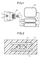
- the measuring device comprises a sensor made up of two electrodes 2,3 to form a capacitor with dielectric material and circuit connected to the electrodes to measure the loss angle of the capacitor.
- the electrodes 2,3 are flat copper wires parallel to each other which are inserted between two consecutive stator conductors 4.5 at a place where insulation 6 is under stress electric during machine operation.
- the two electrodes 2,3 are inserted at the time of winding in slightly spreading the stator conductors. They are separated by the dielectric material. The latter is subject under the same conditions as the rest of the material in the stator, so it is in the same state of aging. They can just as easily be inserted between the last coil conductor and carbon ribbon.
- the sensor measures the insulation between turns and in the second case, the sensor measures the mass insulation.
- the capacitor dielectric is subjected to a field electric with two components.
- the component main Eo is due to the voltage applied to the insulation. This tension is that which intervenes in the process of insulation aging.
- the measurement component Em is of negligible amplitude and is perpendicular to the former. In this configuration, the electric field of no difference in voltage between the electrodes 2,3 of the measurement capacitor, these electrodes parallel to each other and perpendicular to the field Em se finding brought to an intermediate potential compared to the potentials of the stator conductors 4.5 between which they are inserted.
- the measurement circuit includes a primary coil 10 connected to the electrodes 2,3 to constitute a circuit oscillating with the capacitor. It also includes a coil secondary 11 magnetically coupled with the primary coil to form a means of excitation of the oscillating circuit, the coils being arranged on transformer cores to eliminate any galvanic connection.
- the potential of oscillating circuit can therefore be arbitrary if it is compatible with the insulation between the two coils of the oscillating circuit.
- the secondary coil 11 is connected by a part to a pulse generator 12, and secondly to a analysis device 14 through a converter analog digital 13.
- the electrical signal resulting from stimulation by generator 12 is digitized by the converter 13 and analyzed by the device 14 so as to get a measurement of the overvoltage factor at frequency resonance of the oscillating circuit.
- the overvoltage factor measured is representative of the damping of the derived signal by the converter 13.
- the device 14 also includes a comparator to compare the evaluated overvoltage factor with that representative of a dielectric material having an acceptable insulation capacity.
- the device 14 can be a microprocessor system such as a microcomputer classic in itself.
- Figure 3 shows the variation of the angle of losses (axis designated by TD) of the insulation of a coil subject to accelerated aging, depending on a operating voltage expressed in volts (axis designated by T).
- Curve C represents the variation of the angle of losses for a new coil.
- Curve B represents the variation of the loss angle for the coil after 1000 operating hours and curve A represents the variation of the loss angle for the coil after 7600 Hours of operation.
- the principle of the invention is also applicable to a impregnated transformer for example or to any material electrical engineering using solid insulation, as soon as the positioning of the sensor electrodes is still possible.
Landscapes
- Physics & Mathematics (AREA)
- General Physics & Mathematics (AREA)
- Testing Of Short-Circuits, Discontinuities, Leakage, Or Incorrect Line Connections (AREA)
- Testing Relating To Insulation (AREA)
Description
- à placer au moment du bobinage des spires deux électrodes le long d'une spire de la bobine, ces électrodes étant séparées par le matériau diélectrique pour constituer un condensateur, et
- à mesurer l'angle de pertes du condensateur pendant le fonctionnement de la machine.
- La figure 1 représente schématiquement le dispositif selon l'invention.
- La figure 2 représente deux spires d'une bobine équipée d'un capteur de mesure selon l'invention.
- La figure 3 est un graphe donnant l'angle de pertes d'un condensateur pour différentes valeurs de tension et à différents stades de son vieillissement.
- La figure 4 est un graphe donnant l'évolution de la tension aux bornes du capteur de mesure.
Claims (6)
- Dispositif pour mesurer le vieillissement d'un matériau diélectrique dans une machine, notamment un isolant polymère pour bobine de stator, comportant des moyens dans ledit matériau diélectrique pour faire une mesure sur site pendant le fonctionnement de la machine d'une grandeur physique sensible au vieillissement dudit matériau, caractérisé en ce que lesdits moyens de mesure comprennent deux électrodes (2,3) incluses dans ledit matériau et séparées l'une de l'autre par celui-ci pour constituer un condensateur et un circuit (10,11,12,13,14) relié aux électrodes pour mesurer l'angle de pertes du condensateur.
- Dispositif selon la revendication 1, dans lequel le circuit de mesure comporte au moins une bobine (10) pour constituer un circuit oscillant avec le condensateur, un moyen d'excitation (11,12) du circuit oscillant, un moyen de dérivation (13) d'un signal électrique résultant de l'excitation du circuit oscillant et représentatif de son facteur de surtension à la fréquence de résonance du circuit oscillant, et un dispositif (14) servant à évaluer ledit facteur de surtension.
- Dispositif selon la revendication 2, dans lequel l'excitation du circuit oscillant consiste en une impulsion électrique brève, le moyen de dérivation fournissant un signal représentatif de l'amortissement dans le temps de la tension oscillante du circuit oscillant.
- Dispositif selon l'une des revendications 2 ou 3, comprenant en outre un comparateur (14) servant à comparer ledit facteur de surtension évalué avec celui représentatif d'un matériau diélectrique ayant une capacité d'isolation acceptable.
- Procédé pour mesurer le vieillissement d'un matériau diélectrique (6) isolant des spires (4,5) d'une bobine de machine électrique qui soumettent le matériau diélectrique à un champ électrique, caractérisé par le fait qu'il consiste:à placer au moment du bobinage des spires deux électrodes (2,3) le long d'une spire de la bobine, ces électrodes étant séparées par le matériau diélectrique pour constituer un condensateur, età mesurer l'angle de pertes du condensateur pendant le fonctionnement de la machine.
- Procédé selon la revendication 5, dans lequel les deux électrodes sont placées entre deux spires consécutives de la bobine ou entre la dernière spire et la masse.
Applications Claiming Priority (2)
| Application Number | Priority Date | Filing Date | Title |
|---|---|---|---|
| FR9210315 | 1992-08-27 | ||
| FR9210315A FR2695209B1 (fr) | 1992-08-27 | 1992-08-27 | Dispositif et procédé pour mesurer le vieillissement d'un isolant composite polymère pour bobine de stator. |
Publications (2)
| Publication Number | Publication Date |
|---|---|
| EP0585175A1 EP0585175A1 (fr) | 1994-03-02 |
| EP0585175B1 true EP0585175B1 (fr) | 1998-11-11 |
Family
ID=9433043
Family Applications (1)
| Application Number | Title | Priority Date | Filing Date |
|---|---|---|---|
| EP19930402094 Expired - Lifetime EP0585175B1 (fr) | 1992-08-27 | 1993-08-25 | Dispositif et procédé pour mesurer le vieillissement d'un isolant composite polymère pour bobine de stator |
Country Status (4)
| Country | Link |
|---|---|
| EP (1) | EP0585175B1 (fr) |
| DE (1) | DE69322019T2 (fr) |
| ES (1) | ES2125314T3 (fr) |
| FR (1) | FR2695209B1 (fr) |
Cited By (1)
| Publication number | Priority date | Publication date | Assignee | Title |
|---|---|---|---|---|
| DE10135915A1 (de) * | 2001-07-24 | 2003-03-06 | Wimmershoff Rudolf | Diagnose der dielektrischen Alterung von Mehrstoffdielektrika, z.B. Öl/Papier/Pressspan, Öl/Papier oder Masse/Papier mittels Verlustfaktormessungen vor Ort mit Frequenzen kleiner als die Frequenz der öffentlichen, elektrischen Versorgungsnetze |
Families Citing this family (4)
| Publication number | Priority date | Publication date | Assignee | Title |
|---|---|---|---|---|
| RU2229143C1 (ru) * | 2003-02-25 | 2004-05-20 | Санкт-Петербургский государственный политехнический университет | Способ диагностирования корпусной изоляции электрической машины |
| DE102005050112B4 (de) * | 2005-10-04 | 2007-09-13 | Wimmershoff, Rudolf, Prof. Dr.-Ing. | Verfahren zur Diagnose der dielektrischen Alterung an Einzelkomponenten von elektrischen Anlagen und Geräten mittels Verlustfaktormessungen mit Frequenzen kleiner als die Frequenz der öffentlichen, elektrischen Versorgungsnetze |
| CN102662131B (zh) * | 2012-05-25 | 2015-04-15 | 华北电力大学 | 复合绝缘子芯棒老化的判断方法 |
| CN121098061B (zh) * | 2025-11-12 | 2026-02-27 | 华北电力大学(保定) | 一种基于涂层静电喷涂的发电机绕组绝缘失效预防方法 |
Family Cites Families (2)
| Publication number | Priority date | Publication date | Assignee | Title |
|---|---|---|---|---|
| CA1078017A (fr) * | 1977-07-15 | 1980-05-20 | Canadian General Electric Company Limited | Systeme de controle de decharge en couronne |
| FR2590366A1 (fr) * | 1985-11-20 | 1987-05-22 | Rege Nero Didier | Dispositif detecteur d'anomalies sur moteurs alimentes en courant continu |
-
1992
- 1992-08-27 FR FR9210315A patent/FR2695209B1/fr not_active Expired - Fee Related
-
1993
- 1993-08-25 EP EP19930402094 patent/EP0585175B1/fr not_active Expired - Lifetime
- 1993-08-25 ES ES93402094T patent/ES2125314T3/es not_active Expired - Lifetime
- 1993-08-25 DE DE1993622019 patent/DE69322019T2/de not_active Expired - Fee Related
Cited By (2)
| Publication number | Priority date | Publication date | Assignee | Title |
|---|---|---|---|---|
| DE10135915A1 (de) * | 2001-07-24 | 2003-03-06 | Wimmershoff Rudolf | Diagnose der dielektrischen Alterung von Mehrstoffdielektrika, z.B. Öl/Papier/Pressspan, Öl/Papier oder Masse/Papier mittels Verlustfaktormessungen vor Ort mit Frequenzen kleiner als die Frequenz der öffentlichen, elektrischen Versorgungsnetze |
| DE10135915B4 (de) * | 2001-07-24 | 2004-12-02 | Wimmershoff, Rudolf, Prof. Dr.-Ing. | Diagnose der dielektrischen Alterung von Mehrstoffdielektrika mittels Verlustfaktormessungen vor Ort mit Frequenzen kleiner als die Frequenzen der öffentlichen, elektrischen Versorgungsnetze |
Also Published As
| Publication number | Publication date |
|---|---|
| DE69322019D1 (de) | 1998-12-17 |
| ES2125314T3 (es) | 1999-03-01 |
| FR2695209A1 (fr) | 1994-03-04 |
| DE69322019T2 (de) | 1999-06-17 |
| EP0585175A1 (fr) | 1994-03-02 |
| FR2695209B1 (fr) | 1994-09-30 |
Similar Documents
| Publication | Publication Date | Title |
|---|---|---|
| Zoeller et al. | Evaluation and current-response-based identification of insulation degradation for high utilized electrical machines in railway application | |
| CA2082204C (fr) | Methodes et dispositif d'essai haute frequence | |
| US4156846A (en) | Detection of arcing faults in generator windings | |
| JP4378478B2 (ja) | 部分放電開始電圧計測方法及びその装置 | |
| US6087836A (en) | Apparatus for and method of monitoring the status of the insulation on the wire in a winding | |
| FR2695209A1 (fr) | Dispositif et procédé pour mesurer le vieillissement d'un isolant composite polymère pour bobine de stator. | |
| JPS6472080A (en) | Method and apparatus for testing rectifier of brushless ac dynamotor | |
| RU2005136861A (ru) | Способ и комплект измерительного оборудования для оценки электрических параметров молниезащитных систем | |
| US6882173B1 (en) | Method and apparatus detecting shorted turns in an electric generator | |
| FR2588415A1 (fr) | Coupe-circuit pour courant residuel | |
| KR20040008114A (ko) | 소형 전기 기계의 비파괴 절연 시험 방법 및 장치 | |
| EP0005107B1 (fr) | Installation et procédé d'extraction de l'énergie d'une source capacitive avec régulation par commutation shunt | |
| Morshuis et al. | Partial discharge detection using oscillating voltage at different frequencies | |
| JP2002062330A (ja) | コイルターン間絶縁健全性評価装置及び方法 | |
| RU2240571C1 (ru) | Устройство контроля технического состояния обмоток трансформатора | |
| KR20220138592A (ko) | 베어링 전식 시험 장치 | |
| FR2566539A1 (fr) | Procede d'identification de cables electriques et appareil pour la mise en oeuvre de ce procede | |
| US1358179A (en) | Method of testing the insulation of generators in service | |
| SU995031A1 (ru) | Способ контрол целостности обмотки электрической машины | |
| EP3654045B1 (fr) | Procede de detection et de transmission d'information de panne dormante | |
| SU1442944A2 (ru) | Устройство дл испытани междувитковой изол ции обмоток электрических машин | |
| Kotlica | On-line monitoring of power generating systems | |
| SU99870A1 (ru) | Устройство дл возбуждени ударного синхронного генератора | |
| RU2028639C1 (ru) | Устройство для контроля изоляции электродвигателя | |
| JPH0431817Y2 (fr) |
Legal Events
| Date | Code | Title | Description |
|---|---|---|---|
| PUAI | Public reference made under article 153(3) epc to a published international application that has entered the european phase |
Free format text: ORIGINAL CODE: 0009012 |
|
| AK | Designated contracting states |
Kind code of ref document: A1 Designated state(s): AT BE CH DE DK ES FR GB GR IE IT LI LU MC NL PT SE |
|
| 17P | Request for examination filed |
Effective date: 19940624 |
|
| RBV | Designated contracting states (corrected) |
Designated state(s): CH DE ES FR GB IT LI SE |
|
| 17Q | First examination report despatched |
Effective date: 19971015 |
|
| GRAG | Despatch of communication of intention to grant |
Free format text: ORIGINAL CODE: EPIDOS AGRA |
|
| GRAG | Despatch of communication of intention to grant |
Free format text: ORIGINAL CODE: EPIDOS AGRA |
|
| GRAH | Despatch of communication of intention to grant a patent |
Free format text: ORIGINAL CODE: EPIDOS IGRA |
|
| GRAH | Despatch of communication of intention to grant a patent |
Free format text: ORIGINAL CODE: EPIDOS IGRA |
|
| GRAA | (expected) grant |
Free format text: ORIGINAL CODE: 0009210 |
|
| AK | Designated contracting states |
Kind code of ref document: B1 Designated state(s): CH DE ES FR GB IT LI SE |
|
| REG | Reference to a national code |
Ref country code: CH Ref legal event code: EP |
|
| REF | Corresponds to: |
Ref document number: 69322019 Country of ref document: DE Date of ref document: 19981217 |
|
| ITF | It: translation for a ep patent filed | ||
| GBT | Gb: translation of ep patent filed (gb section 77(6)(a)/1977) |
Effective date: 19990128 |
|
| REG | Reference to a national code |
Ref country code: ES Ref legal event code: FG2A Ref document number: 2125314 Country of ref document: ES Kind code of ref document: T3 |
|
| REG | Reference to a national code |
Ref country code: CH Ref legal event code: NV Representative=s name: CABINET ROLAND NITHARDT CONSEILS EN PROPRIETE INDU |
|
| PLBE | No opposition filed within time limit |
Free format text: ORIGINAL CODE: 0009261 |
|
| STAA | Information on the status of an ep patent application or granted ep patent |
Free format text: STATUS: NO OPPOSITION FILED WITHIN TIME LIMIT |
|
| 26N | No opposition filed | ||
| REG | Reference to a national code |
Ref country code: GB Ref legal event code: IF02 |
|
| PGFP | Annual fee paid to national office [announced via postgrant information from national office to epo] |
Ref country code: GB Payment date: 20030728 Year of fee payment: 11 Ref country code: CH Payment date: 20030728 Year of fee payment: 11 |
|
| PGFP | Annual fee paid to national office [announced via postgrant information from national office to epo] |
Ref country code: DE Payment date: 20030805 Year of fee payment: 11 |
|
| PGFP | Annual fee paid to national office [announced via postgrant information from national office to epo] |
Ref country code: ES Payment date: 20030807 Year of fee payment: 11 |
|
| PGFP | Annual fee paid to national office [announced via postgrant information from national office to epo] |
Ref country code: SE Payment date: 20030808 Year of fee payment: 11 |
|
| PGFP | Annual fee paid to national office [announced via postgrant information from national office to epo] |
Ref country code: FR Payment date: 20030813 Year of fee payment: 11 |
|
| PG25 | Lapsed in a contracting state [announced via postgrant information from national office to epo] |
Ref country code: GB Free format text: LAPSE BECAUSE OF NON-PAYMENT OF DUE FEES Effective date: 20040825 |
|
| PG25 | Lapsed in a contracting state [announced via postgrant information from national office to epo] |
Ref country code: SE Free format text: LAPSE BECAUSE OF NON-PAYMENT OF DUE FEES Effective date: 20040826 Ref country code: ES Free format text: LAPSE BECAUSE OF NON-PAYMENT OF DUE FEES Effective date: 20040826 |
|
| PG25 | Lapsed in a contracting state [announced via postgrant information from national office to epo] |
Ref country code: LI Free format text: LAPSE BECAUSE OF NON-PAYMENT OF DUE FEES Effective date: 20040831 Ref country code: CH Free format text: LAPSE BECAUSE OF NON-PAYMENT OF DUE FEES Effective date: 20040831 |
|
| PG25 | Lapsed in a contracting state [announced via postgrant information from national office to epo] |
Ref country code: DE Free format text: LAPSE BECAUSE OF NON-PAYMENT OF DUE FEES Effective date: 20050301 |
|
| EUG | Se: european patent has lapsed | ||
| REG | Reference to a national code |
Ref country code: CH Ref legal event code: PL |
|
| GBPC | Gb: european patent ceased through non-payment of renewal fee |
Effective date: 20040825 |
|
| PG25 | Lapsed in a contracting state [announced via postgrant information from national office to epo] |
Ref country code: FR Free format text: LAPSE BECAUSE OF NON-PAYMENT OF DUE FEES Effective date: 20050429 |
|
| REG | Reference to a national code |
Ref country code: FR Ref legal event code: ST |
|
| PG25 | Lapsed in a contracting state [announced via postgrant information from national office to epo] |
Ref country code: IT Free format text: LAPSE BECAUSE OF NON-PAYMENT OF DUE FEES;WARNING: LAPSES OF ITALIAN PATENTS WITH EFFECTIVE DATE BEFORE 2007 MAY HAVE OCCURRED AT ANY TIME BEFORE 2007. THE CORRECT EFFECTIVE DATE MAY BE DIFFERENT FROM THE ONE RECORDED. Effective date: 20050825 |
|
| REG | Reference to a national code |
Ref country code: ES Ref legal event code: FD2A Effective date: 20040826 |