EP0585031A1 - Control rod servicing apparatus - Google Patents
Control rod servicing apparatus Download PDFInfo
- Publication number
- EP0585031A1 EP0585031A1 EP93306461A EP93306461A EP0585031A1 EP 0585031 A1 EP0585031 A1 EP 0585031A1 EP 93306461 A EP93306461 A EP 93306461A EP 93306461 A EP93306461 A EP 93306461A EP 0585031 A1 EP0585031 A1 EP 0585031A1
- Authority
- EP
- European Patent Office
- Prior art keywords
- pin
- roller
- radioactive
- tool
- control rod
- Prior art date
- Legal status (The legal status is an assumption and is not a legal conclusion. Google has not performed a legal analysis and makes no representation as to the accuracy of the status listed.)
- Granted
Links
Images


Classifications
-
- G—PHYSICS
- G21—NUCLEAR PHYSICS; NUCLEAR ENGINEERING
- G21C—NUCLEAR REACTORS
- G21C19/00—Arrangements for treating, for handling, or for facilitating the handling of, fuel or other materials which are used within the reactor, e.g. within its pressure vessel
- G21C19/02—Details of handling arrangements
-
- G—PHYSICS
- G21—NUCLEAR PHYSICS; NUCLEAR ENGINEERING
- G21C—NUCLEAR REACTORS
- G21C19/00—Arrangements for treating, for handling, or for facilitating the handling of, fuel or other materials which are used within the reactor, e.g. within its pressure vessel
- G21C19/20—Arrangements for introducing objects into the pressure vessel; Arrangements for handling objects within the pressure vessel; Arrangements for removing objects from the pressure vessel
- G21C19/207—Assembling, maintenance or repair of reactor components
-
- Y—GENERAL TAGGING OF NEW TECHNOLOGICAL DEVELOPMENTS; GENERAL TAGGING OF CROSS-SECTIONAL TECHNOLOGIES SPANNING OVER SEVERAL SECTIONS OF THE IPC; TECHNICAL SUBJECTS COVERED BY FORMER USPC CROSS-REFERENCE ART COLLECTIONS [XRACs] AND DIGESTS
- Y02—TECHNOLOGIES OR APPLICATIONS FOR MITIGATION OR ADAPTATION AGAINST CLIMATE CHANGE
- Y02E—REDUCTION OF GREENHOUSE GAS [GHG] EMISSIONS, RELATED TO ENERGY GENERATION, TRANSMISSION OR DISTRIBUTION
- Y02E30/00—Energy generation of nuclear origin
- Y02E30/30—Nuclear fission reactors
-
- Y—GENERAL TAGGING OF NEW TECHNOLOGICAL DEVELOPMENTS; GENERAL TAGGING OF CROSS-SECTIONAL TECHNOLOGIES SPANNING OVER SEVERAL SECTIONS OF THE IPC; TECHNICAL SUBJECTS COVERED BY FORMER USPC CROSS-REFERENCE ART COLLECTIONS [XRACs] AND DIGESTS
- Y10—TECHNICAL SUBJECTS COVERED BY FORMER USPC
- Y10T—TECHNICAL SUBJECTS COVERED BY FORMER US CLASSIFICATION
- Y10T29/00—Metal working
- Y10T29/49—Method of mechanical manufacture
- Y10T29/49718—Repairing
- Y10T29/49721—Repairing with disassembling
- Y10T29/4973—Replacing of defective part
-
- Y—GENERAL TAGGING OF NEW TECHNOLOGICAL DEVELOPMENTS; GENERAL TAGGING OF CROSS-SECTIONAL TECHNOLOGIES SPANNING OVER SEVERAL SECTIONS OF THE IPC; TECHNICAL SUBJECTS COVERED BY FORMER USPC CROSS-REFERENCE ART COLLECTIONS [XRACs] AND DIGESTS
- Y10—TECHNICAL SUBJECTS COVERED BY FORMER USPC
- Y10T—TECHNICAL SUBJECTS COVERED BY FORMER US CLASSIFICATION
- Y10T29/00—Metal working
- Y10T29/53—Means to assemble or disassemble
- Y10T29/531—Nuclear device
Definitions
- the present invention relates generally to nuclear reactors, and, more specifically, to an apparatus and method for servicing control rods therein having radioactive rollers and pins.
- a plurality of control rods are selectively inserted into and withdrawn from a reactor core containing a plurality of nuclear fuel bundles therein.
- the fuel bundles are disposed in flow or fuel channels which are spaced apart from each other to define passages through which the control rods may be translated upwardly or downwardly.
- Exemplary control rods have cruciform cross sections which are disposed in complementary shaped passages between adjacent fuel bundles. As the control rods are translated upwardly and downwardly, they intermittently slide against the fuel channels.
- the control rods In order to reduce abrasion between the sliding control rods and the fuel channels, the control rods typically include pin mounted rollers which provide the sole points of contact between the control rods and the fuel channels as the control rods are translated. In order to reduce wear of the rollers and pins themselves, they are typically formed from conventional abrasion resistant materials containing cobalt. However, it has been determined through operation of the reactors, that the neutron flux within the reactor core irradiates the rollers and pins causing them to become highly radioactive. As the rollers and pins wear and corrode during operation, the particles released thereby remain radioactive and are circulated along with the reactor water channeled through the core. These radioactive particles increase the radiation levels of plant equipment through which the water is circulated.
- the cobalt content of rollers and pins is being reduced or eliminated in newer reactors to reduce or eliminate the increased radiation due to the radioactive cobalt particles.
- the present invention is set forth in Claim 1.
- Features of the present invention are to provide a control rod servicing apparatus and method for removing radioactive cobalt containing rollers and pins from control rods: an apparatus and method for removing the cobalt containing rollers and pins underwater in existing reactors; and an apparatus and method for replacing cobalt containing rollers and pins with non-cobalt containing rollers and pins.
- an apparatus and method for servicing an irradiated nuclear control rod underwater in a reactor building servicing pool.
- a turntable containing a plurality of spaced apart tools is positioned adjacent to the control rod.
- a first tool aligns the turntable relative to the radioactive roller mounted to the control rod by a radioactive pin therethrough.
- the turntable is indexable to position a second tool adjacent to the radioactive roller and pin, with the second tool being effective for freeing the radioactive pin from the control rod.
- the turntable is indexable for positioning a third tool adjacent to the radioactive roller and pin for removing the radioactive pin and the rollerfrom the control rod.
- the turntable is further indexable for positioning a fourth tool adjacent to the control rod for reaming the pin aperture through which the radioactive pin was mounted.
- the turntable further includes a fifth tool which is indexable into position adjacent to the control rod for inserting a replacement roller and replacement pin therein.
- the replacement pin is secured to the control rod by a sixth tool supported on the turntable which is also Indexable into position.
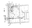
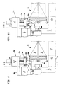
- FIG. 1 Illustrated schematically in Figure 1 is a portion of a reactor building 10 containing a conventional nuclear reactor such as, for example, a boiling water reactor (BWR) 12.
- the reactor 12 includes a conventional pressure vessel 14 containing a conventional nuclear reactor core 16 therein.
- the vessel 14 is illustrated with its upper head (shown in phantom) removed during a maintenance outage.
- the reactor 12 includes a plurality of conventional control rods 18, with an exemplary one shown being removed upwardly from the pressure vessel 14 by a conventional first hoist 20a carried on a conventional movable trolley or bridge 22.
- the reactor building 10 includes a conventional servicing pool 24 suitably filled with water 26 so that the control rods 28 are at all times maintained underwater during the servicing operation.
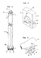
- control rods 18 having a generally cruciform cross- section.
- the control rod 18 has a top end 18a to which is conventionally attached a handle 28.
- the control rod 18 also has a bottom end 18b in the conventional form of an annular velocity limiterfrom which extends a conventional coupling socket 30 which mates with a conventional control rod drive which is used during normal operation for conventionally inserting the control rod 18 into the reactor core 16 from the bottom of the pressure vessel 14 and for withdrawing the control rod 18 therefrom as desired.
- each of the control rods 18 includes a plurality of conventional cobalt containing rollers 32 secured thereto, with four rollers 32 being shown at the top end 18a and four additional rollers 32 shown at the bottom end 18b.
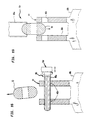
- the control rod 18 includes a plate 34 which is a corner of one of the cruciform portions of the control rod 18 having a roller aperture 36a extending perpendicularly therethrough adjacent to a vertically extending edge 38.
- a pin aperture 40a shown in dashed line extends perpendicularly inwardly in from the edge 38 through a portion of the plate 34 and through the roller aperture 36 to form a blind receptacle for receiving a conventional cobalt containing, elongate mounting pin 42.
- the rollers 32 extend outwardly from each of the four plates 34 defining the cruciform upper end 18a of the control rod 18 for providing rolling points of contact therefor as it moves between adjacent fuel channels in the core 16 during operation for reducing wear therebetween.
- Figure 4 illustrates an alternate embodiment of mounting of the rollers 32 at the control rod bottom end 18b which includes a conventional U-shaped clevis 44 having a pair of spaced apart legs 44a, 44b defining therebetween another form of the roller aperture 36b for receiving the roller 32.
- a pin aperture 40b extends through both the legs 44a, 44b for receiving the mounting pin 42 to secure the roller 32 in the clevis 44.
- the mounting pins 42 of the two embodiments illustrated in Figures 3 and 4 are conventionally fixedly joined to the control rod 18 by conventional plug welds 46.
- the plug weld 46 joins the end of the pin 42 to the edge 38.
- the mounting pin 42 is joined to at least one of the legs 44a, 44b by the plug weld 46, and as shown, is welded at both ends of the pin 42 to the clevis 44.
- the cable of the second hoist 20b initially extends downwardly through the center of the strong back tube 52, with its hook capturing the handle 28 of a control rod 18 for lifting the control rod 18 vertically inside the strong back tube 52.
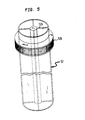
- the tube 52 is illustrated in more particularity in Figure 5 and includes a cruciform channel 52a extending longitudinally therethrough from the top end of the tube 52 to the bottom end of the tube 52 which is complementary in configuration to the cruciform control rod 18 for securely retaining therein the control rod 18.
- the strongback tube 52 provides structural reinforcement of the control rod 18 to prevent damage thereto during the servicing operation and for providing a convenient structure for positioning the control rod 18.
- the tube 52 preferably includes a conventional ring gear 52b fixedly secured to its upper end for selectively rotating the tube 52 and the control rod 18 therein.
- the tube 52 is moved by the trolley 22 underwater to an upender support rail 56 pivotally joined at its upper end 56a to the pool 24.
- a bottom end 56b of the rail 56 is L-shaped and includes a suitable dog onto which the control rod coupling socket 30 is placed for securely mounting the control rod 18 and the strong back tube 52 to the support rail 56.
- the support rail 56 is initially in a vertical orientation and is then conventionally pivoted upwardly by one of the hoists 20a, 20b, for example, into the horizontal position shown in solid line.
- the control rod bottom end 18b is then positioned adjacent to the first machine 48, and the control rod top end 18a is positioned adjacent to the second machine 50.
- the ring gear 52b of the strong back tube 52 is conventionally supported by a pinion gear 58 operatively joined to a conventional electrical motor 60 which can selectively rotate the pinion gear 58 and, in turn, the ring gear 52b for rotating the strongback tube 52 and, in turn, rotating the control rod 18 for positioning the several rollers 32 relative to the machines 48, 50 for the removal thereof. Since the rollers 32 illustrated in Figure 3 and 4 are mounted differently at the top and bottom ends 18a, 18b of the control rods 18, the machines 48, 50 are suitably tailored for removing the rollers 32 but operate similarly.
- the first machine 48 includes a frame 62 conventionally joined to the pool 24, for example to a ledge 24a extending from one of its walls.
- a first base plate or carriage 64a is conventionally mounted to the frame 62 for sliding movement relative thereto.
- conventional means 66 for translating the carriage towards the clevis 44 generally parallel to the longitudinal axis of the control rod 18 are provided for axially sliding the carriage 64a.
- the translating means 66 is in the exemplary form of an electrical motor selectively rotating a drive screw which selectively translates the carriage 64a either toward the clevis 44 or away from the clevis 44 as desired.
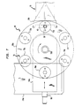
- a conventional first turntable 68a is rotatably joined to the first carriage 64a and includes a plurality of circumferentially spaced apart tools indicated collectively at 70 supported thereon.
- Conventional first means 72a in the form of an electric motor are provided for selectively rotating the turntable 68a to position or index a first one 70a of the tools 70 adjacent to one of the radioactive rollers 32 mounted in the roller aperture 36b.
- Each of the tools 70 includes a conventional drive motor 74 mounted to the top of the turntable 68a having a drive screw 74a extending downwardly therethrough.
- the drive screw 74 is conventionally joined to a tool support 74b which is selectively retracted upwardly away from the roller 32 and selectively translated downwardly adjacent to the roller 32.
- the several tools 70 are substantially identical except for the tool portions mounted to the tool supports 74b and extending downwardly therefrom.
- the first tool 70a illustrated in Figure 6 is an aligner tool having two location probes 76a which are used for aligning the turntable 68a, and in turn the tools 70 thereon, relative to the radioactive roller 32.
- the translating means 66 are effective for positioning the carriage 64a, which supports the turntable 68a and in turn the probes 76, adjacent to the control rod 18, and, in particular, adjacent to a respective roller 32.
- a method in accordance with the present invention includes positioning adjacent to the control rod 18 the carriage 64a containing the tools 70 supported on the turntable 68a and then rotating the turntable 68a to index the first tool 70a adjacent to the radioactive roller 32.
- the method then includes the step of aligning the turntable 68a relative to the radioactive roller 32 using the location probes 76a of the first tool 70a.
- the coordinates of the roller 32 may be stored in a conventional computer 78 which controls operation of the machine 48. Once the location of the roller 32 is accurately determined, a conventional pneumatic clamp 80 may then grip the clevis 44 to secure the clevis 44 in space forfurtheroperations.
- the rotating means 72a are effective for rotating the turntable 68a for successively indexing adjacent to the radioactive roller 32, and pin 42 extending therethrough.
- Each of the tools 70 provides a special operation. such as the first tool 70a providing initial alignment of the turntable 68a and all of the tools 70 thereon relative to the roller 32 and the pin 42.
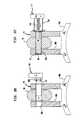
- Figures 8 and 9 illustrate the second tool 70b disposed in position adjacent to the roller 32 and the pin 42
- Figure 10 illustrates the operation of freeing the pin 42 from the clevis 44 of the control rod 18 using the second tool 70b.
- means 82 joined to the tool support 74b of the second tool 70b are means 82 in the exemplary form of a conventional electrical discharge machine (EDM) having at least one, and in this exemplary embodiment two conventional electrodes 82a.
- the electrodes 82a are suitably mounted to the tool support 74b and are selectively translatable by a conventional drive motor 82b alternatively adjacent to the welds 46 on opposite ends of the pin 42.
- the right hand electrode 82a is positioned adjacent to the right end of the pin 42 for electrically eroding away the weld 46 for separating the weld 46 from the clevis 44 for freeing the pin 42 from the control rod 18 at the clevis 44 by removing the weld 46 between the pin 42 and the clevis 44.
- the drive motor 82b then moves both the left hand and right hand electrodes 82a to the right, withdrawing the right hand electrode 82a and positioning the left hand electrode 82a adjacent to the weld 46 at the left end of the pin 42 and then the process is repeated to remove also that weld 46 to entirely free the pin 42 from the clevis 44.
- the EDM 82 is then retracted upwardly away from the roller 32 by the drive screw 74a for the next operation.
- electrical discharge machining is used in the preferred embodiment for removing the welds 46, any suitable alternate process may be used such as grinding, milling, or drilling, for example.
- the method proceeds by rotating the turntable 68a illustrated in Figure 7 to index the third tool 70c adjacent to the roller 32 and pin 42.
- the third tool 70c is shown in position adjacent to the roller 32 and pin 42 in Figures 11-13.
- the third tool 70c is an ejector tool including means 84 for removing the radioactive pin 42 and the roller 32 from the clevis 44 of the control rod 18.
- the removing means 84 include a ram pin 84a operatively joined to a conventional drive motor 84b which is joined to the tool support 74b, with the drive motor 84b being effective for translating the ram pin 84a against one end of the radioactive pin 42 as illustrated in Figure 13 to push the pin 42 through the pin and roller apertures 40b, 36b for removal from the clevis 44.
- the removing means 84 may also include a suitable pin receptacle 84c into which the ejected radioactive pin 42 may be collected for removal from the machine 48.
- Another receptacle (not shown) may also be provided for catching the radioactive roller 32 as it drops from between the clevis 44 upon removal of the pin 42.
- the drive screw 74a then retracts the tool support 74b and the removing means 84 upwardly away from the clevis 44 so that the turntable 68a illustrated in Figure 7 may again be indexed by the rotating means 72a for indexing into position the fourth tool 70d shown in Figures 14-16 adjacent to the pin aperture 40b.
- the fourth tool 70d includes cleaning or reaming means 86 in the conventional form of a reamer 86a for reaming the pin aperture 40b as required to dean up any buildup of corrosion or debris therein.
- the reaming means 86 also include a conventional first drive motor 86b operatively joined to the reamer 86a for selectively rotating the reamer 86a.
- Asecond drive motor 86c as illustrated in Figure 15 is operatively joined to the reamer 86a and the first drive motor 86b for selectively translating the reamer 86a through the pin apertures 40b as the reamer 86a is rotated by the first drive motor 86b.
- the reamer 86a may be suitably retracted, and then the entire reaming means 86 may be retracted upwardly by the drive screw 74a so that the turntable illustrated in Figure 7 may be again rotated for indexing the fifth tool 70e in turn adjacent to the roller aperture 36b of the clevis 44 as shown in Figures 17-20.
- the fifth tool 70e includes means 88 for inserting a non-cobalt bearing replacement roller 90 into the roller aperture 36b. as shown more clearly in Figures 19 and 20, and inserting a noncobalt bearing replacement pin 92 into the reamed pin aperture 40b and through the replacement roller 90 for holding the replacement roller 90 in the roller aperture 36b.
- the inserting means 88 include a roller gripper 88a which may take the conventional form of prongs for inserting the replacement roller 90 into position in the roller aperture 36b in the clevis 44.
- a pin gripper 88b illustrated in Figures 18 and 20 in the form of a conventional chuck may be used to insert the replacement pin 92 through both the pin aperture 40b and the replacement roller 90.
- Another drive motor 88c as shown in Figure 18 is operatively connected to the pin gripper 88b for translating the pin 92 through the clevis 44.
- the pin gripper 88b may be released from the pin 92 and then used itself to push the pin 92 flush with the clevis 44 as required.
- the inserting means 88 may then be retracted upwardly by the drive screw 74a so that the turntable 68a illustrated in Figure 7 may again be rotated to index the sixth tool 70f adjacent to the replacement roller 90 and replacement pin 92 as illustrated in Figures 21 and 22.
- the sixth tool 70f includes means 94 for fixedly securing the replacement pin 92 in the pin aperture 40b for securing the replacement roller 90 in the mounting aperture 36b.
- the securing means 94 may be in the form of a conventional underwater gas tungsten arc welder or tungsten inert gas (TIG) welder including a TIG welding electrode 94a extending through a purge tube 94b.
- TIG welding electrode 94a, 94b are mounted on opposite sides of the clevis 44 and operatively joined to the drive motor 94c for alternately positioning each of the electrodes 94a adjacent to a respective end of the replacement pin 92 as shown. for example, in Figure 22.
- Aconventional inert gas 94d is channeled through the purge tube 94b for purging the water therefrom and initially drying the end of the replacement pin 92 so that the TIG electrode 94a may effectively form a suitable weld 96, shown partly formed at the pin right end in Figure 22, to fixedly join the replacement pin 92 to the clevis 44.
- One or both ends of the replacement pin 92 may be welded to the clevis 44. with both ends being weld thereto as shown in Figure 22.
- the welder 94 may be retracted upwardly to allow the turntable 68a to rotate and again index into position the first tool 70a.
- the motor 60 shown in Figure 1 may then be used to rotate the strongback tube 52 for placing into position a second one of the radioactive rollers 32 and then the entire sequence may be repeated to remove that roller 32 for substitution by another replacement roller 90.
- all four of the original radioactive roller 32 disposed at the control rod bottom end 18b may be removed and if desired, substituted with non-cobalt bearing replacement rollers 90 and replacement pins 92. If replacement rollers and pins 90, 92 are not installed, the control rod 18 may be returned to service without them. or alternate replacements (not shown) could be used instead.
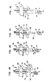
- the second machine 50 although being functionally similar to the first machine 48 is specifically tailored for the different mounting geometry. More specifically, and referring to Figures 23 and 24, the second machine 50 is illustrated schematically in more particularity.
- the first machine 48 the second machine 50 includes a similar second carriage 64b and second turntable 68b, with the carriage 64b being similarly translatable by the positioning means 66.
- the second turntable 68b is similarly rotatable by conventional rotating means 72b to sequentially index similar first through sixth tools 70u-70z.
- the second machine 50 includes means 98 for rotating the second carriage 64b towards the plate edge 38 for positioning the first tool 70u adjacent to the radioactive roller 32.
- the rotating means 98 includes an arm 100 suitably conventionally pivoted at a proximal end 100a and having a U-shaped recess 100b at its distal end configured to fit over the plate 34 as illustrated in Figure 23.
- the second carriage 64b is suitably mounted transversely to the arm 100, and the rotations of the second turntable 68b and the arm 100 are in two perpendicular planes. In this way, the arm 100 may be rotated down so that the recess 100b is positioned over the plate 34 and away from the roller 32. and the second carriage 64b may be translated parallel to the plate 34 to position the first tool 70u directly above the roller 32.
- the first tool 70u is an aligner tool having means 76b in the form of a U-shaped clamp for aligning the turntable 68b relative to the radioactive roller 32.
- the clamp 76b is selectively lowered from the second turntable 68b into position over one of the rollers 32 and is then suitably clamped thereto for holding its position.
- Aconventional actuator 100c at the distal end of the arm 100 is then activated to damp the plate 34 within the recess 100b for holding the control rod 18 in position for all subsequent operations, and then the damp 76b is released and retracted upwardly by the first tool 70u.
- the second turntable 68b may be rotated to index into position the second tool 70v as shown schematically in Figure 25.
- the freeing means 82 of the second tool 70v like the second tool 70b disclosed above include a conventional electrical discharge machine (EDM) having a special, tubular electrode 102 effective for cutting the plate 34 for freeing the radioactive pin 42 from the edge 38 while providing a head 104, shown in dashed line in Figure 25, on the pin 42 which is formed by a portion of the plate 34 at the weld 46.
- EDM electrical discharge machine
- the electrode 102 is shown as preferably including a first generally U-shaped slot 106 specifically configured for alternately eroding away the plate 34 on both sides adjacent to the weld 46 for freeing the radioactive pin 42 while forming the head 104.
- the first slot 106 initially straddles the plate 34 at the welded end of the pin 42 adjacent the edge 38 and is then translated alternately toward each side of the plate 34. Since the first slot 106 is formed in a tubular electrode 102, the resulting EDM slot formed in both sides of the plate 34 is generally crescent-shaped.
- the electrode 102 further includes a pair of opposing second slots 108 having a width on the order of the diameter of the pin 42 so that as the electrode 102 removes material from each side of the plate 34, the pin 42 will not be severed, and the resulting head 104 remains with the pin 42 after the EDM process is finished. In this way, the radioactive pin 42 may be freed from the plate 34, with the weld 46 remaining as part of the head 104.
- the third tool 70w which includes conventional means in the form of a damp or grippers 110 which are effective for gripping the head 104 of the radioactive pin 42 and pulling the pin 42 from the pin aperture 40a to remove the radioactive roller 32.
- the roller 32 may be suitably captured in a receptacle (not shown) and removed from the vicinity for proper disposal thereof.
- the third tool 70w may then be retracted away, and then the second turntable 68b rotated to index into position the fourth tool 70x as illustrated in Figures 31 and 32.
- the fourth tool 70x includes a conventional reamer 86a suitably rotated by the conventional drive motor 86b to conventionally ream the pin aperture 40a as required.
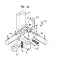
- the reamer 86a is then suitably retracted away with the fourth tool 70x, and again the second turntable 68b is rotated to index into position the fifth tool 70y illustrated schematically in Figures 33 and 34.
- a roller magazine 112 contains a plurality of roller carriers 114 each containing a replacement roller 90.
- a conventional pneumatic ram 116 is used to eject the roller 90 from the carrier 114 and into position within the roller aperture 36a.
- a pin magazine 118 includes a plurality of the replacement pins 92 which are sequentially ejected into position adjacent by a second pneumatic ram 120 which inserts the pin 92 through the pin aperture 40a and through the replacement roller 90 into a fully inserted position.
- the fifth tool 70y is then suitably withdrawn upwardly toward the second turntable 68b, and then the second turntable 68b is again rotated to index into position the sixth tool 70z as illustrated in Figures 35 and 36.
- the sixth tool 70z of the second machine 50 is similar to the sixth tool 70f of the first machine 48 illustrated in Figure 22 except for its orientation extending perpendicularly upwardly from the plate edge 38 and that it includes a single electrode 94a and single purge tube 94b since only one end of the replacement pin 92 is available for welding as shown at the weld 122 illustrated in Figure 36.
- the inert gas 94d is firstly channeled through the purge tube 94b to purge the water away from the end of the replacement pin 92, and then the end is conventionally TIG welded to the plate 34 in the crescent-shaped recess remaining in the plate edge 38.
- the replacement pin 92 is, therefore, similarly welded to the plate edge 38 as in the original design, for securely mounting the replacement roller 90 within the roller aperture 36a.
- the sixth tool 70z is then retracted upwardly toward the second turntable 68b and the first tool 70u is again brought into position.
- the actuator 100c illustrated in Figure 23 is then released for releasing the clamping action of the arm 100, and then the arm 100 is rotated away from the control rod 18.
- the strongback tube 52 illustrated in Figure 1 is then rotated by the motor 60 for placing into position a successive one of the radioactive rollers 32, and then the entire sequence is repeated for replacing the radioactive roller 32 and pin 40 with the non-cobalt bearing replacement roller 90 and pin 92.
- the two machines 48 and 50 illustrated in Figure 1, are therefore effective for removing the radioactive rollers 32 and pins 42 from the control rod 18 at all times underwater which provides additional protection against the radiation being emitted therefrom.
- the removal of the radioactive rollers and pins may be done remotely by the machines 48 and 50 so that operators are not subjected to radiation.
- the control rods 18 may be returned to operation within the reactor core 16 without the radioactive rollers and pins, if desired, or replacement rollers and pins 90. 92 may be inserted by the machines 48 and 50 if desired. In this way, the original control rods 18 may be returned to use in the reactor core 16 for the remainder of their useful lives without further concern for the removed cobalt-bearing rollers and pins 32, 42.
Abstract
Description
- The present invention relates generally to nuclear reactors, and, more specifically, to an apparatus and method for servicing control rods therein having radioactive rollers and pins.
- In a nuclear reactor such as a boiling water reactor (BWR), a plurality of control rods are selectively inserted into and withdrawn from a reactor core containing a plurality of nuclear fuel bundles therein. The fuel bundles are disposed in flow or fuel channels which are spaced apart from each other to define passages through which the control rods may be translated upwardly or downwardly. Exemplary control rods have cruciform cross sections which are disposed in complementary shaped passages between adjacent fuel bundles. As the control rods are translated upwardly and downwardly, they intermittently slide against the fuel channels.
- In order to reduce abrasion between the sliding control rods and the fuel channels, the control rods typically include pin mounted rollers which provide the sole points of contact between the control rods and the fuel channels as the control rods are translated. In order to reduce wear of the rollers and pins themselves, they are typically formed from conventional abrasion resistant materials containing cobalt. However, it has been determined through operation of the reactors, that the neutron flux within the reactor core irradiates the rollers and pins causing them to become highly radioactive. As the rollers and pins wear and corrode during operation, the particles released thereby remain radioactive and are circulated along with the reactor water channeled through the core. These radioactive particles increase the radiation levels of plant equipment through which the water is circulated.
- Accordingly, the cobalt content of rollers and pins is being reduced or eliminated in newer reactors to reduce or eliminate the increased radiation due to the radioactive cobalt particles.
- However, cobalt containing rollers and pins are presently in service in nuclear reactors, and the replacement of the entire control rod including the cobalt containing rollers and pins joined thereto would appear to be impractical and costly.
- The present invention is set forth in
Claim 1. Features of the present invention are to provide a control rod servicing apparatus and method for removing radioactive cobalt containing rollers and pins from control rods: an apparatus and method for removing the cobalt containing rollers and pins underwater in existing reactors; and an apparatus and method for replacing cobalt containing rollers and pins with non-cobalt containing rollers and pins. - In the invention,an apparatus and method are provided for servicing an irradiated nuclear control rod underwater in a reactor building servicing pool. A turntable containing a plurality of spaced apart tools is positioned adjacent to the control rod. A first tool aligns the turntable relative to the radioactive roller mounted to the control rod by a radioactive pin therethrough. The turntable is indexable to position a second tool adjacent to the radioactive roller and pin, with the second tool being effective for freeing the radioactive pin from the control rod. The turntable is indexable for positioning a third tool adjacent to the radioactive roller and pin for removing the radioactive pin and the rollerfrom the control rod. In further embodiments of the invention the turntable is further indexable for positioning a fourth tool adjacent to the control rod for reaming the pin aperture through which the radioactive pin was mounted. The turntable further includes a fifth tool which is indexable into position adjacent to the control rod for inserting a replacement roller and replacement pin therein. The replacement pin is secured to the control rod by a sixth tool supported on the turntable which is also Indexable into position.
- The invention, in accordance with preferred and exemplary embodiments, together with further objects and advantages thereof, is more particularly described in the following detailed description taken in conjunction with the accompanying drawings in which:
- Figure 1 is a schematic, elevation view of a portion of a reactor building including two machines in accordance with respective embodiments of the present invention disposed underwaterfor servicing a control rod.
- Figure 2 is a perspective view of an exemplary nuclear reactor control rod having pin mounted rollers at the top and bottom thereof.
- Figure 3 is an enlarged perspective view of one of the plate-mounted rollers at the top of the control rod illustrated in Figure 2 within the circle labeled 3.
- Figure 4 is an enlarged perspective view of one of the clevis-mounted rollers at the bottom of the control rod illustrated in Figure 2 within the circle labeled 4.
- Figure 5 is a schematic representation of a strong back tube used for supporting the control rod illustrated in Figure 1.
- Figure 6 is an elevation, side view of a first machine for removing and replacing the clevis-mounted rollers and pins at the bottom of the control rod illustrated in Figure 1 shown with a first tool in position.
- Figure 7 is a top view of the first machine illustrated in Figure 6 taken along line 7-7 showing six tools mounted on a turntable.
- Figure 8 is an elevation, side view of the second tool illustrated in Figure 7 in position adjacent to one of the rollers.
- Figure 9 is an elevation, partly sectional transverse view of the second tool illustrated in Figure 8 taken along line 9-9.
- Figure 10 is an enlarged, elevation, partly sectional view of a portion of the second tool illustrated in Figure 9 adjacent to the clevis mounted roller and pin.
- Figure 11 is an elevation, side view of the third tool illustrated in Figure 7 in position adjacent to the clevis mounted roller.
- Figure 12 is an elevation, partly transverse sectional view of the third tool illustrated in Figure 11 taken along line 12-12.
- Figure 13 is an enlarged, elevation, partly sectional view of a portion of the third tool illustrated in Figure 12 adjacent to the clevis mounted roller.
- Figure 14 is an elevation, side view of the fourth tool shown in Figure 7 in position adjacent to the clevis mounted roller.
- Figure 15 is an elevational, partly sectional transverse view of a portion of the fourth tool illustrated in Figure 14 taken along line 15-15.
- Figure 16 is an enlarged, elevation, partly sectional view of a portion of the fourth tool illustrated in Figure 15 adjacent to the clevis.
- Figure 17 is an elevation, side view of the fifth tool of Figure 7 in position adjacent to the clevis.
- Figure 18 is an elevational, partly sectional transverse view of the fifth tool illustrated in Figure 17 taken along line 18-18.
- Figure 19 is an enlarged elevational, partly sectional view of a portion of the fifth tool illustrated in Figure 18 showing a replacement roller being inserted into the clevis.
- Figure 20 is an enlarged elevational, partly sectional view of a portion of the fifth tool illustrated in Figure 18 showing a replacement pin being inserted into the clevis.
- Figure 21 is an elevational, partly sectional transverse view of the sixth tool illustrated in Figure 7 in position adjacent to the clevis.
- Figure 22 is an enlarged, elevation. partly sectional view of a portion of the sixth tool illusted in Figure 21 adjacent to the clevis.
- Figure 23 is a schematic representation of a second machine for removing and replacing plate-mounted rollers and pins, and including a turntable having six tools mounted thereon.
- Figure 24 is an enlarged, schematic view of the first tool illustrated in Figure 23.
- Figure 25 is an enlarged, schematic view of the second tool illustrated in Figure 23.
- Figure 26 is a top view of the plate-mounted roller illustrated in Figure 23 and an electrode of the second tool disposed adjacent thereto.
- Figure 27 is an elevational, sectional view of the plate-mounted roller illustrated in Figure 26 taken along line 27.27.
- Figure 28 is an elevational, partly sectional view of the plate-mounted roller illustrated in Figure 26 taken along line 28-28.
- Figure 29 is an elevational, schematic view of the third tool illustrated in Figure 23.
- Figure 30 is an elevational, partly sectional view of the plate-mounted roller illustrated in Figure 29 showing removal of the pin.
- Figure 31 is an elevational, schematic view of the fourth tool illustrated in Figure 23 adjacent to the control rod plate.
- Figure 32 is an enlarged, partly sectional view of the control rod plate illustrated in Figure 31 adjacent to the fourth tool.
- Figure 33 is a schematic. partly exploded representation of the fifth tool joined to the turntable illustrated in Figure 23 adjacent to the control rod plate.
- Figure 34 is an enlarged, partly sectional view of the control rod plate illustrated in Figure 33 adjacent to the fifth tool.
- Figure 35 is an elevational, schematic view of the sixth tool joined to the turntable illustrated in Figure 23 adjacent to the control rod plate.
- Figure 36 is an enlarged, partly sectional view of the control rod plate adjacent to the sixth tool illustrated in Figure 35.
- Illustrated schematically in Figure 1 is a portion of a
reactor building 10 containing a conventional nuclear reactor such as, for example, a boiling water reactor (BWR) 12. Thereactor 12 includes aconventional pressure vessel 14 containing a conventionalnuclear reactor core 16 therein. Thevessel 14 is illustrated with its upper head (shown in phantom) removed during a maintenance outage. Thereactor 12 includes a plurality ofconventional control rods 18, with an exemplary one shown being removed upwardly from thepressure vessel 14 by a conventional first hoist 20a carried on a conventional movable trolley orbridge 22. Thereactor building 10 includes aconventional servicing pool 24 suitably filled withwater 26 so that thecontrol rods 28 are at all times maintained underwater during the servicing operation. - Illustrated in Figure 2 is an exemplary one of the
control rods 18 having a generally cruciform cross- section. Thecontrol rod 18 has atop end 18a to which is conventionally attached ahandle 28. Thecontrol rod 18 also has abottom end 18b in the conventional form of an annular velocity limiterfrom which extends aconventional coupling socket 30 which mates with a conventional control rod drive which is used during normal operation for conventionally inserting thecontrol rod 18 into thereactor core 16 from the bottom of thepressure vessel 14 and for withdrawing thecontrol rod 18 therefrom as desired. - During insertion and withdrawal of the
control rod 18 during operation, the cruciform portions thereof intermittently slide against conventional flow or fuel channels (not shown) within thereactor core 16. In order to reduce sliding wear between thecontrol rods 18 and the fuel channels during operation, each of thecontrol rods 18 includes a plurality of conventionalcobalt containing rollers 32 secured thereto, with fourrollers 32 being shown at thetop end 18a and fouradditional rollers 32 shown at thebottom end 18b. - The
rollers 32 are illustrated in more particularity in Figures 3 and 4 in two different mounting arrangements. In Figure 3, thecontrol rod 18 includes aplate 34 which is a corner of one of the cruciform portions of thecontrol rod 18 having aroller aperture 36a extending perpendicularly therethrough adjacent to a vertically extendingedge 38. Apin aperture 40a shown in dashed line extends perpendicularly inwardly in from theedge 38 through a portion of theplate 34 and through the roller aperture 36 to form a blind receptacle for receiving a conventional cobalt containing, elongate mountingpin 42. Therollers 32 extend outwardly from each of the fourplates 34 defining the cruciformupper end 18a of thecontrol rod 18 for providing rolling points of contact therefor as it moves between adjacent fuel channels in the core 16 during operation for reducing wear therebetween. - Figure 4 illustrates an alternate embodiment of mounting of the
rollers 32 at the control rodbottom end 18b which includes a conventionalU-shaped clevis 44 having a pair of spaced apartlegs 44a, 44b defining therebetween another form of theroller aperture 36b for receiving theroller 32. Apin aperture 40b extends through both thelegs 44a, 44b for receiving the mountingpin 42 to secure theroller 32 in theclevis 44. The mounting pins 42 of the two embodiments illustrated in Figures 3 and 4 are conventionally fixedly joined to thecontrol rod 18 by conventional plug welds 46. In Figure 3, theplug weld 46 joins the end of thepin 42 to theedge 38. And, in Figure 4, the mountingpin 42 is joined to at least one of thelegs 44a, 44b by theplug weld 46, and as shown, is welded at both ends of thepin 42 to theclevis 44. - During normal operation of the
control rod 18 in thereactor core 16, the neutron flux therein irradiates thecobalt containing rollers 32 and pins 42 and thereby causes them to become radioactive. In accordance with the present invention, two apparatuses ormachines servicing pool 24 are provided for removing theradioactive rollers 32 and pins 42 from thecontrol rods 18. In order to position each of thecontrol rods 18 adjacent to themachines strongback tube 52 is conventionally supported in thepool 24 by a conventional grapple 54 joined to a conventional second hoist 20b carried by thetrolley 22. The cable of the second hoist 20b initially extends downwardly through the center of thestrong back tube 52, with its hook capturing thehandle 28 of acontrol rod 18 for lifting thecontrol rod 18 vertically inside thestrong back tube 52. Thetube 52 is illustrated in more particularity in Figure 5 and includes acruciform channel 52a extending longitudinally therethrough from the top end of thetube 52 to the bottom end of thetube 52 which is complementary in configuration to thecruciform control rod 18 for securely retaining therein thecontrol rod 18. Thestrongback tube 52 provides structural reinforcement of thecontrol rod 18 to prevent damage thereto during the servicing operation and for providing a convenient structure for positioning thecontrol rod 18. For this purpose, thetube 52 preferably includes aconventional ring gear 52b fixedly secured to its upper end for selectively rotating thetube 52 and thecontrol rod 18 therein. - More specifically, and referring again to Figure 1, once the
control rod 18 is lifted in position inside thestrongback tube 52, thetube 52 is moved by thetrolley 22 underwater to anupender support rail 56 pivotally joined at itsupper end 56a to thepool 24. Abottom end 56b of therail 56 is L-shaped and includes a suitable dog onto which the controlrod coupling socket 30 is placed for securely mounting thecontrol rod 18 and thestrong back tube 52 to thesupport rail 56. As shown in phantom line in Figure 1, thesupport rail 56 is initially in a vertical orientation and is then conventionally pivoted upwardly by one of thehoists bottom end 18b is then positioned adjacent to thefirst machine 48, and the control rodtop end 18a is positioned adjacent to thesecond machine 50. Thering gear 52b of thestrong back tube 52 is conventionally supported by apinion gear 58 operatively joined to a conventionalelectrical motor 60 which can selectively rotate thepinion gear 58 and, in turn, thering gear 52b for rotating thestrongback tube 52 and, in turn, rotating thecontrol rod 18 for positioning theseveral rollers 32 relative to themachines rollers 32 illustrated in Figure 3 and 4 are mounted differently at the top and bottom ends 18a, 18b of thecontrol rods 18, themachines rollers 32 but operate similarly. - More specifically, and referring to Figures 6 and 7, the
first machine 48 is illustrated in more detail. Thefirst machine 48 includes aframe 62 conventionally joined to thepool 24, for example to aledge 24a extending from one of its walls. A first base plate orcarriage 64a is conventionally mounted to theframe 62 for sliding movement relative thereto. More specifically. conventional means 66 for translating the carriage towards theclevis 44 generally parallel to the longitudinal axis of thecontrol rod 18 are provided for axially sliding thecarriage 64a. The translating means 66 is in the exemplary form of an electrical motor selectively rotating a drive screw which selectively translates thecarriage 64a either toward theclevis 44 or away from theclevis 44 as desired. A conventionalfirst turntable 68a is rotatably joined to thefirst carriage 64a and includes a plurality of circumferentially spaced apart tools indicated collectively at 70 supported thereon. Conventionalfirst means 72a in the form of an electric motor are provided for selectively rotating theturntable 68a to position or index a first one 70a of thetools 70 adjacent to one of theradioactive rollers 32 mounted in theroller aperture 36b. - Each of the
tools 70 includes aconventional drive motor 74 mounted to the top of theturntable 68a having adrive screw 74a extending downwardly therethrough. Thedrive screw 74 is conventionally joined to atool support 74b which is selectively retracted upwardly away from theroller 32 and selectively translated downwardly adjacent to theroller 32. Theseveral tools 70 are substantially identical except for the tool portions mounted to the tool supports 74b and extending downwardly therefrom. - More specifically, the
first tool 70a illustrated in Figure 6 is an aligner tool having two location probes 76a which are used for aligning theturntable 68a, and in turn thetools 70 thereon, relative to theradioactive roller 32. The translating means 66 are effective for positioning thecarriage 64a, which supports theturntable 68a and in turn the probes 76, adjacent to thecontrol rod 18, and, in particular, adjacent to arespective roller 32. - Accordingly, a method in accordance with the present invention includes positioning adjacent to the
control rod 18 thecarriage 64a containing thetools 70 supported on theturntable 68a and then rotating theturntable 68a to index thefirst tool 70a adjacent to theradioactive roller 32. The method then includes the step of aligning theturntable 68a relative to theradioactive roller 32 using the location probes 76a of thefirst tool 70a. The coordinates of theroller 32 may be stored in aconventional computer 78 which controls operation of themachine 48. Once the location of theroller 32 is accurately determined, a conventionalpneumatic clamp 80 may then grip theclevis 44 to secure theclevis 44 in space forfurtheroperations. - As illustrated in Figure 7, the rotating
means 72a are effective for rotating theturntable 68a for successively indexing adjacent to theradioactive roller 32, and pin 42 extending therethrough. second. third, fourth, fifth, andsixth tools tools 70 provides a special operation. such as thefirst tool 70a providing initial alignment of theturntable 68a and all of thetools 70 thereon relative to theroller 32 and thepin 42. - Figures 8 and 9 illustrate the
second tool 70b disposed in position adjacent to theroller 32 and thepin 42, and Figure 10 illustrates the operation of freeing thepin 42 from theclevis 44 of thecontrol rod 18 using thesecond tool 70b. More specifically, joined to thetool support 74b of thesecond tool 70b are means 82 in the exemplary form of a conventional electrical discharge machine (EDM) having at least one, and in this exemplary embodiment twoconventional electrodes 82a. Theelectrodes 82a are suitably mounted to thetool support 74b and are selectively translatable by aconventional drive motor 82b alternatively adjacent to thewelds 46 on opposite ends of thepin 42. As shown in Figure 10, theright hand electrode 82a is positioned adjacent to the right end of thepin 42 for electrically eroding away theweld 46 for separating theweld 46 from theclevis 44 for freeing thepin 42 from thecontrol rod 18 at theclevis 44 by removing theweld 46 between thepin 42 and theclevis 44. Thedrive motor 82b then moves both the left hand andright hand electrodes 82a to the right, withdrawing theright hand electrode 82a and positioning theleft hand electrode 82a adjacent to theweld 46 at the left end of thepin 42 and then the process is repeated to remove also thatweld 46 to entirely free thepin 42 from theclevis 44. TheEDM 82 is then retracted upwardly away from theroller 32 by thedrive screw 74a for the next operation. Although electrical discharge machining is used in the preferred embodiment for removing thewelds 46, any suitable alternate process may be used such as grinding, milling, or drilling, for example. - The method proceeds by rotating the
turntable 68a illustrated in Figure 7 to index thethird tool 70c adjacent to theroller 32 andpin 42. Thethird tool 70c is shown in position adjacent to theroller 32 andpin 42 in Figures 11-13. Thethird tool 70c is an ejector tool including means 84 for removing theradioactive pin 42 and theroller 32 from theclevis 44 of thecontrol rod 18. The removing means 84 include aram pin 84a operatively joined to aconventional drive motor 84b which is joined to thetool support 74b, with thedrive motor 84b being effective for translating theram pin 84a against one end of theradioactive pin 42 as illustrated in Figure 13 to push thepin 42 through the pin androller apertures clevis 44. As shown in Figure 13, the removingmeans 84 may also include asuitable pin receptacle 84c into which the ejectedradioactive pin 42 may be collected for removal from themachine 48. Another receptacle (not shown) may also be provided for catching theradioactive roller 32 as it drops from between theclevis 44 upon removal of thepin 42. Thedrive screw 74a then retracts thetool support 74b and the removingmeans 84 upwardly away from theclevis 44 so that theturntable 68a illustrated in Figure 7 may again be indexed by the rotatingmeans 72a for indexing into position thefourth tool 70d shown in Figures 14-16 adjacent to thepin aperture 40b. - The
fourth tool 70d includes cleaning or reaming means 86 in the conventional form of areamer 86a for reaming thepin aperture 40b as required to dean up any buildup of corrosion or debris therein. The reaming means 86 also include a conventionalfirst drive motor 86b operatively joined to thereamer 86a for selectively rotating thereamer 86a.Asecond drive motor 86c as illustrated in Figure 15 is operatively joined to thereamer 86a and thefirst drive motor 86b for selectively translating thereamer 86a through thepin apertures 40b as thereamer 86a is rotated by thefirst drive motor 86b. Once thepin aperture 40b is suitably cleaned thereamer 86a may be suitably retracted, and then the entire reaming means 86 may be retracted upwardly by thedrive screw 74a so that the turntable illustrated in Figure 7 may be again rotated for indexing thefifth tool 70e in turn adjacent to theroller aperture 36b of theclevis 44 as shown in Figures 17-20. - The
fifth tool 70e includes means 88 for inserting a non-cobaltbearing replacement roller 90 into theroller aperture 36b. as shown more clearly in Figures 19 and 20, and inserting a noncobaltbearing replacement pin 92 into the reamedpin aperture 40b and through thereplacement roller 90 for holding thereplacement roller 90 in theroller aperture 36b. As shown in Figures 17 and 19, the insertingmeans 88 include aroller gripper 88a which may take the conventional form of prongs for inserting thereplacement roller 90 into position in theroller aperture 36b in theclevis 44. Apin gripper 88b illustrated in Figures 18 and 20 in the form of a conventional chuck may be used to insert thereplacement pin 92 through both thepin aperture 40b and thereplacement roller 90. Anotherdrive motor 88c as shown in Figure 18 is operatively connected to thepin gripper 88b for translating thepin 92 through theclevis 44. Thepin gripper 88b may be released from thepin 92 and then used itself to push thepin 92 flush with theclevis 44 as required. The inserting means 88 may then be retracted upwardly by thedrive screw 74a so that theturntable 68a illustrated in Figure 7 may again be rotated to index thesixth tool 70f adjacent to thereplacement roller 90 andreplacement pin 92 as illustrated in Figures 21 and 22. - The
sixth tool 70f includes means 94 for fixedly securing thereplacement pin 92 in thepin aperture 40b for securing thereplacement roller 90 in the mountingaperture 36b. For example, the securing means 94 may be in the form of a conventional underwater gas tungsten arc welder or tungsten inert gas (TIG) welder including aTIG welding electrode 94a extending through apurge tube 94b. As shown in Figure 21, two opposing electrodes andpurge tubes clevis 44 and operatively joined to thedrive motor 94c for alternately positioning each of theelectrodes 94a adjacent to a respective end of thereplacement pin 92 as shown. for example, in Figure 22. Aconventionalinert gas 94d is channeled through thepurge tube 94b for purging the water therefrom and initially drying the end of thereplacement pin 92 so that theTIG electrode 94a may effectively form asuitable weld 96, shown partly formed at the pin right end in Figure 22, to fixedly join thereplacement pin 92 to theclevis 44. One or both ends of thereplacement pin 92 may be welded to theclevis 44. with both ends being weld thereto as shown in Figure 22. - Once welding of the
replacement pin 92 is completed, thewelder 94 may be retracted upwardly to allow theturntable 68a to rotate and again index into position thefirst tool 70a. Themotor 60 shown in Figure 1 may then be used to rotate thestrongback tube 52 for placing into position a second one of theradioactive rollers 32 and then the entire sequence may be repeated to remove thatroller 32 for substitution by anotherreplacement roller 90. In this way, all four of the originalradioactive roller 32 disposed at the control rodbottom end 18b may be removed and if desired, substituted with non-cobaltbearing replacement rollers 90 and replacement pins 92. If replacement rollers and pins 90, 92 are not installed, thecontrol rod 18 may be returned to service without them. or alternate replacements (not shown) could be used instead. - Since the mounting arrangement of the
rollers 32 in theclevises 44 of the control rodbottom end 18a as shown in Figure 4 is different than the mounting arrangement of therollers 32 at the control rodtop end 18a as shown in Figure 3, thesecond machine 50, although being functionally similar to thefirst machine 48 is specifically tailored for the different mounting geometry. More specifically, and referring to Figures 23 and 24, thesecond machine 50 is illustrated schematically in more particularity. Uke thefirst machine 48, thesecond machine 50 includes a similarsecond carriage 64b andsecond turntable 68b, with thecarriage 64b being similarly translatable by the positioning means 66. Thesecond turntable 68b is similarly rotatable by conventionalrotating means 72b to sequentially index similar first throughsixth tools 70u-70z. - In order to complement the cruciform configuration of the control rod
top end 18a, thesecond machine 50 includesmeans 98 for rotating thesecond carriage 64b towards theplate edge 38 for positioning thefirst tool 70u adjacent to theradioactive roller 32. The rotating means 98 includes anarm 100 suitably conventionally pivoted at aproximal end 100a and having aU-shaped recess 100b at its distal end configured to fit over theplate 34 as illustrated in Figure 23. Thesecond carriage 64b is suitably mounted transversely to thearm 100, and the rotations of thesecond turntable 68b and thearm 100 are in two perpendicular planes. In this way, thearm 100 may be rotated down so that therecess 100b is positioned over theplate 34 and away from theroller 32. and thesecond carriage 64b may be translated parallel to theplate 34 to position thefirst tool 70u directly above theroller 32. - The
first tool 70u is an aligner tool having means 76b in the form of a U-shaped clamp for aligning theturntable 68b relative to theradioactive roller 32. As shown in Figures 23 and 24, theclamp 76b is selectively lowered from thesecond turntable 68b into position over one of therollers 32 and is then suitably clamped thereto for holding its position.Aconventional actuator 100c at the distal end of thearm 100 is then activated to damp theplate 34 within therecess 100b for holding thecontrol rod 18 in position for all subsequent operations, and then the damp 76b is released and retracted upwardly by thefirst tool 70u. Once theradioactive roller 32 is properly aligned relative to thesecond turntable 68b by this step, thesecond turntable 68b may be rotated to index into position thesecond tool 70v as shown schematically in Figure 25. - The freeing means 82 of the
second tool 70v like thesecond tool 70b disclosed above include a conventional electrical discharge machine (EDM) having a special,tubular electrode 102 effective for cutting theplate 34 for freeing theradioactive pin 42 from theedge 38 while providing ahead 104, shown in dashed line in Figure 25, on thepin 42 which is formed by a portion of theplate 34 at theweld 46. - More specifically, and referring to Figures 26-28, the
electrode 102 is shown as preferably including a first generallyU-shaped slot 106 specifically configured for alternately eroding away theplate 34 on both sides adjacent to theweld 46 for freeing theradioactive pin 42 while forming thehead 104. As shown in Figure 26. thefirst slot 106 initially straddles theplate 34 at the welded end of thepin 42 adjacent theedge 38 and is then translated alternately toward each side of theplate 34. Since thefirst slot 106 is formed in atubular electrode 102, the resulting EDM slot formed in both sides of theplate 34 is generally crescent-shaped. Theelectrode 102 further includes a pair of opposingsecond slots 108 having a width on the order of the diameter of thepin 42 so that as theelectrode 102 removes material from each side of theplate 34, thepin 42 will not be severed, and the resultinghead 104 remains with thepin 42 after the EDM process is finished. In this way, theradioactive pin 42 may be freed from theplate 34, with theweld 46 remaining as part of thehead 104. - Shown schematically in Figures 29 and 30 is the third tool 70w which includes conventional means in the form of a damp or
grippers 110 which are effective for gripping thehead 104 of theradioactive pin 42 and pulling thepin 42 from thepin aperture 40a to remove theradioactive roller 32. Once thepin 42 is removed, theroller 32 may be suitably captured in a receptacle (not shown) and removed from the vicinity for proper disposal thereof. - The third tool 70w may then be retracted away, and then the
second turntable 68b rotated to index into position thefourth tool 70x as illustrated in Figures 31 and 32. Thefourth tool 70x includes aconventional reamer 86a suitably rotated by theconventional drive motor 86b to conventionally ream thepin aperture 40a as required. Thereamer 86a is then suitably retracted away with thefourth tool 70x, and again thesecond turntable 68b is rotated to index into position thefifth tool 70y illustrated schematically in Figures 33 and 34. - In Figure 33, a
roller magazine 112 contains a plurality ofroller carriers 114 each containing areplacement roller 90. A conventionalpneumatic ram 116 is used to eject theroller 90 from thecarrier 114 and into position within theroller aperture 36a. Apin magazine 118 includes a plurality of the replacement pins 92 which are sequentially ejected into position adjacent by a secondpneumatic ram 120 which inserts thepin 92 through thepin aperture 40a and through thereplacement roller 90 into a fully inserted position. Thefifth tool 70y is then suitably withdrawn upwardly toward thesecond turntable 68b, and then thesecond turntable 68b is again rotated to index into position thesixth tool 70z as illustrated in Figures 35 and 36. - The
sixth tool 70z of thesecond machine 50 is similar to thesixth tool 70f of thefirst machine 48 illustrated in Figure 22 except for its orientation extending perpendicularly upwardly from theplate edge 38 and that it includes asingle electrode 94a andsingle purge tube 94b since only one end of thereplacement pin 92 is available for welding as shown at theweld 122 illustrated in Figure 36. Again, theinert gas 94d is firstly channeled through thepurge tube 94b to purge the water away from the end of thereplacement pin 92, and then the end is conventionally TIG welded to theplate 34 in the crescent-shaped recess remaining in theplate edge 38. Thereplacement pin 92 is, therefore, similarly welded to theplate edge 38 as in the original design, for securely mounting thereplacement roller 90 within theroller aperture 36a. - The
sixth tool 70z is then retracted upwardly toward thesecond turntable 68b and thefirst tool 70u is again brought into position. Theactuator 100c illustrated in Figure 23 is then released for releasing the clamping action of thearm 100, and then thearm 100 is rotated away from thecontrol rod 18. Thestrongback tube 52 illustrated in Figure 1 is then rotated by themotor 60 for placing into position a successive one of theradioactive rollers 32, and then the entire sequence is repeated for replacing theradioactive roller 32 and pin 40 with the non-cobaltbearing replacement roller 90 andpin 92. - The two
machines radioactive rollers 32 and pins 42 from thecontrol rod 18 at all times underwater which provides additional protection against the radiation being emitted therefrom. The removal of the radioactive rollers and pins may be done remotely by themachines control rods 18 may be returned to operation within thereactor core 16 without the radioactive rollers and pins, if desired, or replacement rollers and pins 90. 92 may be inserted by themachines original control rods 18 may be returned to use in thereactor core 16 for the remainder of their useful lives without further concern for the removed cobalt-bearing rollers and pins 32, 42. - While there have been described herein what are considered to be preferred embodiments of the present invention, other modifications of the invention shall be apparent to those skilled in the art from the teachings herein, and it is, therefore, desired to be secured in the appended claims all such modifications as fall within the scope of the invention claimed.
Claims (10)
Applications Claiming Priority (2)
| Application Number | Priority Date | Filing Date | Title |
|---|---|---|---|
| US07/932,175 US5243631A (en) | 1992-08-19 | 1992-08-19 | Control rod servicing apparatus and method |
| US932175 | 1992-08-19 |
Publications (2)
| Publication Number | Publication Date |
|---|---|
| EP0585031A1 true EP0585031A1 (en) | 1994-03-02 |
| EP0585031B1 EP0585031B1 (en) | 1996-05-15 |
Family
ID=25461895
Family Applications (1)
| Application Number | Title | Priority Date | Filing Date |
|---|---|---|---|
| EP93306461A Expired - Lifetime EP0585031B1 (en) | 1992-08-19 | 1993-08-17 | Control rod servicing apparatus |
Country Status (5)
| Country | Link |
|---|---|
| US (1) | US5243631A (en) |
| EP (1) | EP0585031B1 (en) |
| DE (1) | DE69302641T2 (en) |
| ES (1) | ES2087661T3 (en) |
| TW (1) | TW253060B (en) |
Families Citing this family (12)
| Publication number | Priority date | Publication date | Assignee | Title |
|---|---|---|---|---|
| DE4403149C2 (en) * | 1994-02-17 | 1995-09-07 | Herbert Wenzel | Pneumatically and hydraulically operated recovery grab for nuclear power plants and industry |
| JP3757122B2 (en) * | 2001-02-23 | 2006-03-22 | 株式会社日立製作所 | Control rod for boiling water reactor |
| TWI298156B (en) | 2002-10-24 | 2008-06-21 | Tian Holdings Llc | Discrimination method for light storage device |
| CN100412972C (en) | 2003-09-15 | 2008-08-20 | 宇田控股有限公司 | Method for ascertaining the format of an loaded optical disc |
| US20050226114A1 (en) | 2004-03-31 | 2005-10-13 | Stanley Liow | Method and apparatus for generating absolute time in pregroove data |
| US7746745B2 (en) | 2004-05-25 | 2010-06-29 | Ricky Chang | Method for determining the type of digital versatile disc |
| US7626907B2 (en) | 2004-05-25 | 2009-12-01 | Ricky Chang | Method and apparatus for determining type of digital versatile disc |
| US7570561B2 (en) | 2004-05-25 | 2009-08-04 | Bryan Tai | Method for determining type of digital versatile discs |
| DE102008014544A1 (en) * | 2008-03-15 | 2009-09-17 | Areva Np Gmbh | Device for repairing a damaged area in a submerged wall area of a container or basin |
| CA2694883C (en) * | 2010-02-25 | 2016-08-09 | Hydro-Quebec | Robot for tooling a structural part under water |
| US8867690B2 (en) * | 2011-08-25 | 2014-10-21 | Babcock & Wilcox Mpower, Inc. | Pressurized water reactor with compact passive safety systems |
| CN109778789B (en) * | 2018-04-04 | 2020-08-25 | 水利部交通运输部国家能源局南京水利科学研究院 | Concrete panel rock-fill dam panel goaf underwater repair system |
Citations (5)
| Publication number | Priority date | Publication date | Assignee | Title |
|---|---|---|---|---|
| DE3035857A1 (en) * | 1979-09-29 | 1981-04-02 | Tokyo Shibaura Denki K.K., Kawasaki, Kanagawa | CONTROL STICK FOR A CORE REACTOR |
| EP0096891A1 (en) * | 1982-06-14 | 1983-12-28 | General Signal Corporation | Method and apparatus for changing filters in nuclear power stations |
| SU1135697A1 (en) * | 1984-01-05 | 1985-01-23 | Всесоюзный научно-исследовательский проектно-конструкторский технологический институт механизации труда в черной металлургии и ремонтно-механических работ | Device for replacing rollers of belt conveyor |
| EP0445033A1 (en) * | 1990-02-28 | 1991-09-04 | Cogema (Compagnie Generale Des Matieres Nucleaires) | Mobile intervention confinement allowing access to an installation in a hot cell |
| SU1713701A1 (en) * | 1989-03-13 | 1992-02-23 | Производственное объединение "Новокраматорский машиностроительный завод" | Apparatus for changing rolling stand rolls |
Family Cites Families (1)
| Publication number | Priority date | Publication date | Assignee | Title |
|---|---|---|---|---|
| JPS5952228B2 (en) * | 1980-07-09 | 1984-12-18 | 株式会社日立製作所 | Sliding structure for nuclear reactor |
-
1992
- 1992-08-19 US US07/932,175 patent/US5243631A/en not_active Expired - Fee Related
-
1993
- 1993-04-01 TW TW082102428A patent/TW253060B/zh active
- 1993-08-17 DE DE69302641T patent/DE69302641T2/en not_active Expired - Fee Related
- 1993-08-17 EP EP93306461A patent/EP0585031B1/en not_active Expired - Lifetime
- 1993-08-17 ES ES93306461T patent/ES2087661T3/en not_active Expired - Lifetime
Patent Citations (5)
| Publication number | Priority date | Publication date | Assignee | Title |
|---|---|---|---|---|
| DE3035857A1 (en) * | 1979-09-29 | 1981-04-02 | Tokyo Shibaura Denki K.K., Kawasaki, Kanagawa | CONTROL STICK FOR A CORE REACTOR |
| EP0096891A1 (en) * | 1982-06-14 | 1983-12-28 | General Signal Corporation | Method and apparatus for changing filters in nuclear power stations |
| SU1135697A1 (en) * | 1984-01-05 | 1985-01-23 | Всесоюзный научно-исследовательский проектно-конструкторский технологический институт механизации труда в черной металлургии и ремонтно-механических работ | Device for replacing rollers of belt conveyor |
| SU1713701A1 (en) * | 1989-03-13 | 1992-02-23 | Производственное объединение "Новокраматорский машиностроительный завод" | Apparatus for changing rolling stand rolls |
| EP0445033A1 (en) * | 1990-02-28 | 1991-09-04 | Cogema (Compagnie Generale Des Matieres Nucleaires) | Mobile intervention confinement allowing access to an installation in a hot cell |
Non-Patent Citations (2)
| Title |
|---|
| DATABASE WPI Week 8533, Derwent World Patents Index; AN 85-202044 * |
| DATABASE WPI Week 9302, Derwent World Patents Index; AN 93-016321 * |
Also Published As
| Publication number | Publication date |
|---|---|
| ES2087661T3 (en) | 1996-07-16 |
| DE69302641T2 (en) | 1997-01-16 |
| US5243631A (en) | 1993-09-07 |
| TW253060B (en) | 1995-08-01 |
| DE69302641D1 (en) | 1996-06-20 |
| EP0585031B1 (en) | 1996-05-15 |
Similar Documents
| Publication | Publication Date | Title |
|---|---|---|
| EP0585031B1 (en) | Control rod servicing apparatus | |
| US4742609A (en) | Automatic metal machining center system | |
| US4522780A (en) | Removal and replacement of fuel rods in nuclear fuel assembly | |
| US4796341A (en) | Plate routing method and apparatus | |
| JPS6333997B2 (en) | ||
| EP0276528A1 (en) | System and method for consolidating spent fuel rods | |
| US7112017B2 (en) | Method and apparatus for machining a blank from all directions | |
| US6980620B2 (en) | Device for positioning and axially aligning a fuel assembly and process and apparatus for restoring a positioning element | |
| US4590661A (en) | Hobbing machine tool changer having vertically and horizontally movable jaws | |
| EP0295451B1 (en) | A system for removing and consolidating the fuel rods of a nuclear fuel assembly | |
| CA1260821A (en) | Means and an arrangement for separating fuel rods in a fuel element | |
| KR20210111299A (en) | Minimally Invasive Microsampler for Intact Removal of Surface Deposits and Substrates | |
| US4649609A (en) | Apparatus and process for providing an alternate coolant path in the core of a nuclear reactor | |
| JP2896524B2 (en) | Tungsten electrode automatic changer | |
| KR100817435B1 (en) | Automated welding equipment and method for the flange of the guide thimble tube in the nuclear fuel assembly | |
| US4669174A (en) | Tool exchange arrangement for a multi-spindle machine tool | |
| JP5008132B2 (en) | Welding torch electrode changer | |
| EP0594381B1 (en) | Control blade servicing assembly | |
| EP0164991A2 (en) | Metal disintegration machining apparatus | |
| CN115890251A (en) | Automatic machining equipment for hydraulic oil cylinder barrel assembly | |
| CN219805385U (en) | Steel collar processing equipment with guiding function | |
| CN110076473B (en) | Automatic welding equipment for lock rod | |
| COQUERELLE et al. | FOR DISPOSAL | |
| CN107088684B (en) | Spent fuel rod cutting device and method | |
| WO2023164783A1 (en) | Systems and method for combined removal of a calandria tube and a pressure tube |
Legal Events
| Date | Code | Title | Description |
|---|---|---|---|
| PUAI | Public reference made under article 153(3) epc to a published international application that has entered the european phase |
Free format text: ORIGINAL CODE: 0009012 |
|
| AK | Designated contracting states |
Kind code of ref document: A1 Designated state(s): CH DE ES LI SE |
|
| 17P | Request for examination filed |
Effective date: 19940902 |
|
| 17Q | First examination report despatched |
Effective date: 19950831 |
|
| GRAH | Despatch of communication of intention to grant a patent |
Free format text: ORIGINAL CODE: EPIDOS IGRA |
|
| GRAA | (expected) grant |
Free format text: ORIGINAL CODE: 0009210 |
|
| AK | Designated contracting states |
Kind code of ref document: B1 Designated state(s): CH DE ES LI SE |
|
| REG | Reference to a national code |
Ref country code: CH Ref legal event code: NV Representative=s name: RITSCHER & SEIFERT PATENTANWAELTE VSP |
|
| REG | Reference to a national code |
Ref country code: ES Ref legal event code: BA2A Ref document number: 2087661 Country of ref document: ES Kind code of ref document: T3 |
|
| REF | Corresponds to: |
Ref document number: 69302641 Country of ref document: DE Date of ref document: 19960620 |
|
| REG | Reference to a national code |
Ref country code: ES Ref legal event code: FG2A Ref document number: 2087661 Country of ref document: ES Kind code of ref document: T3 |
|
| PGFP | Annual fee paid to national office [announced via postgrant information from national office to epo] |
Ref country code: CH Payment date: 19960731 Year of fee payment: 4 |
|
| PGFP | Annual fee paid to national office [announced via postgrant information from national office to epo] |
Ref country code: SE Payment date: 19960807 Year of fee payment: 4 Ref country code: ES Payment date: 19960807 Year of fee payment: 4 |
|
| PLBE | No opposition filed within time limit |
Free format text: ORIGINAL CODE: 0009261 |
|
| STAA | Information on the status of an ep patent application or granted ep patent |
Free format text: STATUS: NO OPPOSITION FILED WITHIN TIME LIMIT |
|
| PG25 | Lapsed in a contracting state [announced via postgrant information from national office to epo] |
Ref country code: DE Effective date: 19970501 |
|
| 26N | No opposition filed | ||
| PG25 | Lapsed in a contracting state [announced via postgrant information from national office to epo] |
Ref country code: SE Free format text: LAPSE BECAUSE OF NON-PAYMENT OF DUE FEES Effective date: 19970818 Ref country code: ES Free format text: LAPSE BECAUSE OF NON-PAYMENT OF DUE FEES Effective date: 19970818 |
|
| PG25 | Lapsed in a contracting state [announced via postgrant information from national office to epo] |
Ref country code: LI Free format text: LAPSE BECAUSE OF NON-PAYMENT OF DUE FEES Effective date: 19970831 Ref country code: CH Free format text: LAPSE BECAUSE OF NON-PAYMENT OF DUE FEES Effective date: 19970831 |
|
| K1C1 | Correction of patent application (title page) published |
Effective date: 19940302 |
|
| REG | Reference to a national code |
Ref country code: CH Ref legal event code: PL |
|
| EUG | Se: european patent has lapsed |
Ref document number: 93306461.0 |
|
| REG | Reference to a national code |
Ref country code: ES Ref legal event code: FD2A Effective date: 19980910 |