EP0584737B1 - Exhaust gas purifying catalyst - Google Patents
Exhaust gas purifying catalyst Download PDFInfo
- Publication number
- EP0584737B1 EP0584737B1 EP93113345A EP93113345A EP0584737B1 EP 0584737 B1 EP0584737 B1 EP 0584737B1 EP 93113345 A EP93113345 A EP 93113345A EP 93113345 A EP93113345 A EP 93113345A EP 0584737 B1 EP0584737 B1 EP 0584737B1
- Authority
- EP
- European Patent Office
- Prior art keywords
- catalyst
- porous silica
- layered porous
- exhaust gas
- layered
- Prior art date
- Legal status (The legal status is an assumption and is not a legal conclusion. Google has not performed a legal analysis and makes no representation as to the accuracy of the status listed.)
- Expired - Lifetime
Links
Images


Classifications
-
- B—PERFORMING OPERATIONS; TRANSPORTING
- B01—PHYSICAL OR CHEMICAL PROCESSES OR APPARATUS IN GENERAL
- B01J—CHEMICAL OR PHYSICAL PROCESSES, e.g. CATALYSIS OR COLLOID CHEMISTRY; THEIR RELEVANT APPARATUS
- B01J29/00—Catalysts comprising molecular sieves
- B01J29/03—Catalysts comprising molecular sieves not having base-exchange properties
- B01J29/0308—Mesoporous materials not having base exchange properties, e.g. Si-MCM-41
-
- B—PERFORMING OPERATIONS; TRANSPORTING
- B01—PHYSICAL OR CHEMICAL PROCESSES OR APPARATUS IN GENERAL
- B01D—SEPARATION
- B01D53/00—Separation of gases or vapours; Recovering vapours of volatile solvents from gases; Chemical or biological purification of waste gases, e.g. engine exhaust gases, smoke, fumes, flue gases, aerosols
- B01D53/34—Chemical or biological purification of waste gases
- B01D53/92—Chemical or biological purification of waste gases of engine exhaust gases
- B01D53/94—Chemical or biological purification of waste gases of engine exhaust gases by catalytic processes
- B01D53/9404—Removing only nitrogen compounds
- B01D53/9409—Nitrogen oxides
- B01D53/9413—Processes characterised by a specific catalyst
- B01D53/9418—Processes characterised by a specific catalyst for removing nitrogen oxides by selective catalytic reduction [SCR] using a reducing agent in a lean exhaust gas
-
- B—PERFORMING OPERATIONS; TRANSPORTING
- B01—PHYSICAL OR CHEMICAL PROCESSES OR APPARATUS IN GENERAL
- B01D—SEPARATION
- B01D53/00—Separation of gases or vapours; Recovering vapours of volatile solvents from gases; Chemical or biological purification of waste gases, e.g. engine exhaust gases, smoke, fumes, flue gases, aerosols
- B01D53/34—Chemical or biological purification of waste gases
- B01D53/92—Chemical or biological purification of waste gases of engine exhaust gases
- B01D53/94—Chemical or biological purification of waste gases of engine exhaust gases by catalytic processes
- B01D53/9445—Simultaneously removing carbon monoxide, hydrocarbons or nitrogen oxides making use of three-way catalysts [TWC] or four-way-catalysts [FWC]
-
- B—PERFORMING OPERATIONS; TRANSPORTING
- B01—PHYSICAL OR CHEMICAL PROCESSES OR APPARATUS IN GENERAL
- B01D—SEPARATION
- B01D53/00—Separation of gases or vapours; Recovering vapours of volatile solvents from gases; Chemical or biological purification of waste gases, e.g. engine exhaust gases, smoke, fumes, flue gases, aerosols
- B01D53/34—Chemical or biological purification of waste gases
- B01D53/92—Chemical or biological purification of waste gases of engine exhaust gases
- B01D53/94—Chemical or biological purification of waste gases of engine exhaust gases by catalytic processes
- B01D53/9445—Simultaneously removing carbon monoxide, hydrocarbons or nitrogen oxides making use of three-way catalysts [TWC] or four-way-catalysts [FWC]
- B01D53/945—Simultaneously removing carbon monoxide, hydrocarbons or nitrogen oxides making use of three-way catalysts [TWC] or four-way-catalysts [FWC] characterised by a specific catalyst
-
- B—PERFORMING OPERATIONS; TRANSPORTING
- B01—PHYSICAL OR CHEMICAL PROCESSES OR APPARATUS IN GENERAL
- B01D—SEPARATION
- B01D53/00—Separation of gases or vapours; Recovering vapours of volatile solvents from gases; Chemical or biological purification of waste gases, e.g. engine exhaust gases, smoke, fumes, flue gases, aerosols
- B01D53/34—Chemical or biological purification of waste gases
- B01D53/92—Chemical or biological purification of waste gases of engine exhaust gases
- B01D53/94—Chemical or biological purification of waste gases of engine exhaust gases by catalytic processes
- B01D53/9481—Catalyst preceded by an adsorption device without catalytic function for temporary storage of contaminants, e.g. during cold start
-
- B—PERFORMING OPERATIONS; TRANSPORTING
- B01—PHYSICAL OR CHEMICAL PROCESSES OR APPARATUS IN GENERAL
- B01J—CHEMICAL OR PHYSICAL PROCESSES, e.g. CATALYSIS OR COLLOID CHEMISTRY; THEIR RELEVANT APPARATUS
- B01J21/00—Catalysts comprising the elements, oxides, or hydroxides of magnesium, boron, aluminium, carbon, silicon, titanium, zirconium, or hafnium
- B01J21/06—Silicon, titanium, zirconium or hafnium; Oxides or hydroxides thereof
- B01J21/08—Silica
-
- B—PERFORMING OPERATIONS; TRANSPORTING
- B01—PHYSICAL OR CHEMICAL PROCESSES OR APPARATUS IN GENERAL
- B01J—CHEMICAL OR PHYSICAL PROCESSES, e.g. CATALYSIS OR COLLOID CHEMISTRY; THEIR RELEVANT APPARATUS
- B01J29/00—Catalysts comprising molecular sieves
- B01J29/03—Catalysts comprising molecular sieves not having base-exchange properties
- B01J29/0308—Mesoporous materials not having base exchange properties, e.g. Si-MCM-41
- B01J29/0316—Mesoporous materials not having base exchange properties, e.g. Si-MCM-41 containing iron group metals, noble metals or copper
- B01J29/0325—Noble metals
-
- B—PERFORMING OPERATIONS; TRANSPORTING
- B01—PHYSICAL OR CHEMICAL PROCESSES OR APPARATUS IN GENERAL
- B01J—CHEMICAL OR PHYSICAL PROCESSES, e.g. CATALYSIS OR COLLOID CHEMISTRY; THEIR RELEVANT APPARATUS
- B01J35/00—Catalysts, in general, characterised by their form or physical properties
- B01J35/60—Catalysts, in general, characterised by their form or physical properties characterised by their surface properties or porosity
- B01J35/64—Pore diameter
- B01J35/647—2-50 nm
-
- B—PERFORMING OPERATIONS; TRANSPORTING
- B01—PHYSICAL OR CHEMICAL PROCESSES OR APPARATUS IN GENERAL
- B01D—SEPARATION
- B01D2255/00—Catalysts
- B01D2255/10—Noble metals or compounds thereof
- B01D2255/102—Platinum group metals
- B01D2255/1021—Platinum
-
- B—PERFORMING OPERATIONS; TRANSPORTING
- B01—PHYSICAL OR CHEMICAL PROCESSES OR APPARATUS IN GENERAL
- B01D—SEPARATION
- B01D2255/00—Catalysts
- B01D2255/90—Physical characteristics of catalysts
- B01D2255/912—HC-storage component incorporated in the catalyst
-
- B—PERFORMING OPERATIONS; TRANSPORTING
- B01—PHYSICAL OR CHEMICAL PROCESSES OR APPARATUS IN GENERAL
- B01D—SEPARATION
- B01D2255/00—Catalysts
- B01D2255/90—Physical characteristics of catalysts
- B01D2255/92—Dimensions
- B01D2255/9202—Linear dimensions
-
- Y—GENERAL TAGGING OF NEW TECHNOLOGICAL DEVELOPMENTS; GENERAL TAGGING OF CROSS-SECTIONAL TECHNOLOGIES SPANNING OVER SEVERAL SECTIONS OF THE IPC; TECHNICAL SUBJECTS COVERED BY FORMER USPC CROSS-REFERENCE ART COLLECTIONS [XRACs] AND DIGESTS
- Y02—TECHNOLOGIES OR APPLICATIONS FOR MITIGATION OR ADAPTATION AGAINST CLIMATE CHANGE
- Y02A—TECHNOLOGIES FOR ADAPTATION TO CLIMATE CHANGE
- Y02A50/00—TECHNOLOGIES FOR ADAPTATION TO CLIMATE CHANGE in human health protection, e.g. against extreme weather
- Y02A50/20—Air quality improvement or preservation, e.g. vehicle emission control or emission reduction by using catalytic converters
-
- Y—GENERAL TAGGING OF NEW TECHNOLOGICAL DEVELOPMENTS; GENERAL TAGGING OF CROSS-SECTIONAL TECHNOLOGIES SPANNING OVER SEVERAL SECTIONS OF THE IPC; TECHNICAL SUBJECTS COVERED BY FORMER USPC CROSS-REFERENCE ART COLLECTIONS [XRACs] AND DIGESTS
- Y02—TECHNOLOGIES OR APPLICATIONS FOR MITIGATION OR ADAPTATION AGAINST CLIMATE CHANGE
- Y02T—CLIMATE CHANGE MITIGATION TECHNOLOGIES RELATED TO TRANSPORTATION
- Y02T10/00—Road transport of goods or passengers
- Y02T10/10—Internal combustion engine [ICE] based vehicles
- Y02T10/12—Improving ICE efficiencies
Definitions
- the present invention relates to an exhaust gas purifying catalyst for purifying hydrocarbon, carbon monoxide or nitrogen oxides (NO x ) contained in exhaust gases exhausted from an internal combustion engines of automobiles and the like.
- inorganic porous body such as alumina or zeolite is mainly used as a support of an exhaust gas purifying catalyst for automobiles.
- Japanese Laid-Open Patent Publication No. 201648/1987 Patent Abstracts of Japan 62 C 477) discloses various kinds of supports such as alumina, silica, titania and alumina-silica.
- Japanese Laid-Open Patent Publication No. 147153/1980 Patent Abstracts of Japan 71 C 42
- Japanese Laid-Open Patent Publication No. 4220/1989 Patent Abstracts of Japan 24 C 589) discloses crystalline zeolite.
- Japanese Laid-Open Patent Publication No. 63552/1990 discloses composite oxides comprising titanium, nitrogen and zirconia.
- Japanese Laid-Open Patent Publication No. 245850/1989 discloses an aggregate comprising ceramic fibers.
- the above inorganic porous bodies have wide specific surface, acidity and heat resistance at high temperature, so they are suitable for catalytic supports. These supports are used as conventional exhaust gas purifying catalysts in such a manner that a noble metal such as platinum or rhodium is loaded on these supports.
- cold HC is the problem, for it is included in the exhaust gas at low temperature immediately after the engine is ignited and it is hard to be purified by catalysts.
- an exhaust gas purifying apparatus such as cold HC purifying system and the like which use adsorbent such as zeolite for temporarily trapping cold HC (Japanese Patent Laid-Open No. 2-75327/1990 (US-A-4 985 210) and Japanese Patent Application No. 3-49658/1991 (Patent Abstracts of Japan 44 C 832)).
- hydrocarbon components which are trapped by zeolite as the adsorbent, are limited to have relatively small molecules.
- this apparatus it is difficult to efficiently trap bulky aromatic HC such as trimethylbenzene which causes troubles in some countries as the material having the high capacity of forming ozone. This may be related to the small pore diameters for trapping in zeolite.
- Zeolite has the low heat resistance, so it is hard to directly be provided in the exhaust gas system of an internal combustion engines. Therefore, zeolite should be provided in the system with a bypass or the like.
- DE-A-3 928 760 discloses an exhaust gas purifying apparatus comprising an adsorbent and a catalyst, said adsorbent being a zeolite provided on the upstream side of the catalyst.
- USP No. 4,774,213 discloses a catalyst for decreasing the content of nitrogen oxide in flue gases.
- the catalyst comprises an active constituent in form of a combination of a compound of iron and of an acid alumino silicate that has a layered structure, said iron being inserted e.g. by impregnation.
- EP-A-0 472 144 is directed to a method for producing synthetic Magadiite, which might be used as catalyst component, adsorbent or catalytical active agents.
- EP-A-0 284 278 discloses a hydrocracking catalyst which is a layered silicate containing interspathic polymeric silica and interspathic polymeric oxides of one or more metals, said catalyst optionally comprises a catalytic element such as Pd.
- the exhaust gas purifying catalyst according to the present invention comprises at least one kind of catalyst metal which is loaded on a layered porous silica or a layered porous silica-metal oxide as specified in claim 1.
- the layered porous silica or the layered porous silica-metal oxide has the structure that the skeleton comprises SiO 2 or SiO 2 metal composite oxide.
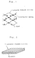
- the layered porous silica or the layered porous silica-metal oxide has the basic structure that a plural of planar sheets 10 are piled up each other. As shown in Figure 1, each of these sheets 10 are curved, and one sheet 10 is partially connected to the other sheet 10 to form a three-dimensional skeleton. Among these layers, there are plural of pores 2 whose diameter is in the range of 1 to 6 nm (10 to 60 angstroms). M is metal element except Si.
- the layered porous silica is used in the forms of spherical particles, prismatic particles or the like. Considering to secure the gas permeability of its filling part and the contacting area of gas, the dimensions of particles are preferably as follows: the diameter of spherical particle falls in the range of 0.1 to 10mm; the diameter of prismatic particle falls in the range of 0.1 to 5mm and the length of prismatic particle falls in the range of 1 to 30mm.
- the layered porous silica may also be used by being loaded on a support comprising appropriate material and having a certain configuration (such as an opening three dimensions ped).
- the specific surface (surface area) of the above layered porous silica is in the range of 1000 to 1500m 2 /g.
- the exhaust gas purifying catalyst according to the present invention has the structure that a fine particle of catalyst metal 3 is loaded on the inner portion of the pore 2 of a layered porous silica 1 or a layered porous silica-metal oxide 1.
- the loaded amount of the catalyst metal is desirably not less than 0.03% by weight against the layered porous silica. When the loaded amount of the catalyst metal is less than 0.03% by weight, no catalytic action occurs.
- the catalyst metals include noble metals, transition metals and rare earth metals. Among these, noble metals are preferable. Especially, platinum is the most preferable. Since the layered porous silica and platinum or the layered porous silica-metal oxide and platinum show high affinity, platinum is widely dispersed and loaded. Furthermore, sintering of platinum particles at high temperature is prevented.
- the layered porous silica is manufactured by the following manner. At first, crystalline layered silicate such as kanemite is heated and agitated in alkyl trimethyl ammonium aqueous solution to generate a layered crystal. Then, an organic substance is introduced into the layers of the layered crystal by means of ion exchange reaction to form an interlayered bridge of SiO 2 . This is referred to as an interlayered extension process. After that, the above layered crystal is filtered, dried and calcined at the temperature of 700°C to obtain the layered porous silica.
- crystalline layered silicate such as kanemite is heated and agitated in alkyl trimethyl ammonium aqueous solution to generate a layered crystal.
- an organic substance is introduced into the layers of the layered crystal by means of ion exchange reaction to form an interlayered bridge of SiO 2 . This is referred to as an interlayered extension process.
- the above layered crystal is filtered, dried and calcined at the temperature of
- the layered porous silica-metal oxide is manufactured by the following manner. At first, crystalline layered silicate is heated and agitated in alkyl trimethyl ammonium aqueous solution. Then, it is filtered and contacted with metallic salt other than silicon. This is referred to as a metal addition process. After that, it is calcined at high temperature to obtain the layered porous silica-metal oxide.
- Crystalline layered silicate for forming a layered porous silica is represented by crystalline layered sodium silicate containing sodium ion between silicon tetrahedral layers.
- Crystalline layered sodium silicate include kanemite (NaHSi 2 O 5 ⁇ 3H 2 O), sodium subsilicate (Na 2 Si 2 O 5 ), macatite (Na 2 Si 4 O 5 ⁇ 5H 2 O), airaite (Na 2 Si 8 O 17 ⁇ xH 2 O), magadiite (Na 2 Si 14 O 23 ⁇ xH 2 O), kenyaite (Na 2 Si 20 O 41 ⁇ xH 2 O) and so on.
- crystalline layered sodium silicate is not limited to the above substance.
- the above crystalline layered silicate contains no structural water, it is different from clay mineral. Hydroxyl group of silanols is used for forming interlayered bridge formation of SiO 2 by means of condensation in the interlayered extension process. So, the pore structure of the crystalline layered silicate is not deteriorated at high temperature. Concerning kanemite which is one kind of crystalline layered silicate, layered crystal comprises single silicon tetrahedral layer, so the surface area per unit weight is wide, and the monolayer structure cannot be deteriorated under the calcination treatment at high temeprature.
- the layered porous silica or the layered porous silica-metal oxide is formed by using kanemite, the specific area becomes wide, and catalytic ability improves.
- kanemite is used for forming the layered porous silica or the layered porous silica-metal oxide, the upper layer is partially connected with the lower layer while maintaining the monolayer structure, and the non-connected portion has pores comprising organic substance.
- the layered porous silica or the layered porous silica-metal oxide has porous structure having honey-comb shaped cross section.
- the above pore diameter is depended on the size of organic substance which is used in the process for forming the layered porous silica or the layered porous silica-metal oxide. However, when the pore diameter is less than 1 nm (10 angstroms) which is the same size of zeolite, it has no effect on the forming.
- the pore diameter is more than 10 nm (100 angstroms), the corresponding organic substance is a few, and validity is less.
- the distribution of the pore diameter can be within the uniformly narrow ranges, and it can be within the wide ranges of 1 to 4 nm (10 to 40 angstroms).
- Interlayered bridge formation of SiO 2 is formed in such a manner that concentration occurs between two hydroxyl groups which are connected to silicon of two silicon tetrahedral layers opposed each other in the interlayered extension process.
- the layered porous silica-metal oxide has acidity.
- the acidity is generated when metallic atom is connected to a part of silicon which constitutes the silicon tetrahedral layer by way of oxygen. Therefore, the acidity functions as Lewis acid. Furthermore, the acidity functions as Br ⁇ nsted acid when water is added to the acidity to discharge proton. In both cases, the acidity exhibits catalytic activity.
- Metallic atoms which has the acidity include aluminum, zirconium, gallium, beryllium, magnesium, yttrium, lanthanum, tin, lead and the like.
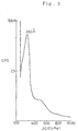
- the structural analysis of the layered porous silica are shown as follows. Concerning one sample in which cetyl trimethyl ammonium chloride is used as an organic substance, the peak corresponding to 3,8 nm (38 angstrom) is observed by powder X-ray diffraction (See Figure 3). Since the peak corresponds to the layer distance, the layered porous silica has the layered structure having the layer space of 3,8 nm (38 angstroms).
- kanemite which is used as raw material shows the peak corresponding to Q 3 of Si (representing the condition that one of four oxygen atoms is free).
- the layered porous silica shows the peak corresponding to Q 4 of Si (representing the condition that none of four oxygen atoms is free) (See Figure 4).
- the layered porous silica has layer bonding and three-dimensional network.
- the method for forming the layered porous silica or the layered porous silica-metal oxide is described as follows.
- the organic substance is introduced into silicon tetrahedral layers in the interlayered extension process, and cation of organic substance reacts with sodium ion to make ion exchange reaction.
- crystalline layered sodium silicate such as kanemite has no lubricating ability with water, it is different from clay mineral and it is hard to cause interlayered extension.
- organic onium ion especially, alkyl ammonium ion is preferable since it is excellent in easy sample preparation and ion exchanging ability.
- Molecular size and molecular weight of the organic substance directly regulate the degree of interlayered extension, namely, the pore diameter of the layered porous silica or the layered porous silica-metal oxide. So, the pore diameter is freely decided by optimum selection of molecular size and molecular weight.
- the distribution of the pore diameter it can be set within uniformly narrow ranges when single kind of organic substance is used.
- the distribution of the pore diameter can be set within wide ranges.
- the layered crystal of SiO 4 tetrahedra can be immersed into the metallic salt solution, and the powder of the layered crystal of SiO 4 tetrahedra can be mixed and contacted with the powder of the metallic salt.
- the metallic salt solution it is preferable that the layered crystal of SiO 4 tetrahedra is dried after immersing in order to improve the efficiency of the calcination process.
- calcination In the calcination process, it is desirable that calcination is normally performed at the temperature of 500 to 800°C for hours. When the calcination temperature is too high, the structure of the layered porous silica is likely to be deteriorated. On the other hand, when the calcination temperature is too low, the structure of the layered porous silica is not fully fixed. There is no limit to calcination condition, so the layered porous silica can be calcined in the air. Furthermore, it also can be calcined in the atmosphere including oxygen or ozone in order to improve decomposition of organic substance.
- the catalyst metal such as platinum is loaded on the above layered porous silica or the above layered porous silica-metal oxide.
- the method for loading the catalyst metal is performed in such a manner that the layered porous silica or the layered porous silica-metal oxide is immersed into the solution of the catalyst metal compound to vaporize moisture, and to be calcined, for example, at the temperature of 350°C.
- An exhaust gas purifying apparatus is provided in an exhaust system of an internal combustion engine, and it comprises an installation portion of an exhaust gas purifying catalyst and an installation portion of adsorbent for trapping hydrocarbon components as specified in claim 2.
- the above-described layered porous silica or the above-described layered porous silica-metal oxide is used as the adsorbent as specified in claim 2.
- the above-mentioned internal combustion engine may be represented by a gasoline engine or diesel engine, but it is not limited to these engines.
- the exhaust gas system of internal combustion engine indicates totally from an exhaust manifold to the tip of an exhaust port of an exhaust pipe.
- the portion of providing exhaust gas purifying apparatus is not limited.
- Exhaust gas purifying catalyst should at least be the catalyst which has the activity for purifying HC in exhaust gas. So, for example, so called oxidation catalyst or three way catalyst is used as exhaust gas purifying catalyst.
- the kind and use of the catalyst or the kind of activated metal which is loaded by the catalyst are not limited. Activated metal may be selected from Pt (platinum), Pd (palladium), Pt-Pd, Pt-Rh (rhodium), Pd-Rh, Pt-V 2 O 5 (vanadium oxide) and the like.
- the arrangements of the providing portion of adsorbent in the exhaust system and the providing portion of the exhaust gas purifying catalyst reside in the following two patterns.
- the former is provided at the upstream side and in the other pattern, the latter is provided at the upstream and the downstream side of the former (refer to Figures 8 to 10).
- the providing portion of adsorbent can reside in the exhaust system or also can reside in the bypass provided in the exhaust system.
- the adsorbent is at least one of the above-mentioned layered porous silica and layered porous silica-metal oxide. Both of the above-mentioned layered porous silica may be combined to be used as the adsorbent or other kinds of adsorbents having a high heat resistance may also be used together.
- the use of these adsorbents is not limited but the examples include a pellet form and the form in which they are coated on support such as cordierite, metal honeycomb and the like.
- the specific surface of the layered porous silica or the layered porous silica-metal oxide is 2 to 7.5 times as large as the conventional catalyst support such as alumina (having the specific surface of 200 to 300m 2 /g). So, it is possible to load much amount of catalyst metal high-dispersively. Concerning catalytic reaction, the more the active spot is, the faster the reaction speed is, and the higher the activity is. Therefore, when the catalyst metal which functions as active spot is highly dispersed, the number of active spot increases and the activity becomes high.
- the exhaust gas purifying catalyst according to the present invention has plenty of fine pores being 1 to 6 nm (10 to 60 angstroms) on its support. Since the pore diameter is slightly larger than the particle diameter of hydrocarbon (being 0.5 to 1.5 nm (5 to 15 angstroms)), hydrocarbon having low concentration in exhaust gases can be effectively trapped to be contacted with oxygen or NO x .
- the conventional layered porous silica such as zeolite has small pore diameter being less than 1 nm (10 angstroms), so hydrocarbon cannot be trapped. Or even if hydrocarbon can be trapped, catalytic activity cannot be fully generated since hydrocarbon cannot be dispersed into the inner side of the pore.
- the pore diameter is enough large for hydrocarbon to be dispersed into the inner side of the pore to be effectively reacted on the catalyst metal.
- cold HC including unburned gasoline vapor
- the catalyst is in the state being not warmed up yet, so the ability for purifying exhaust gas is not sufficiently exercised. Accordingly, cold HC is hardly purified.
- the above-mentioned cold HC is adsorbed and stocked by the layered porous silica or the layered porous silica-metal oxide as the adsorbent, so the cold HC is not exhausted in the atmosphere.
- Aromatic HC such as trimethylbenzene and the like which are not effectively trapped by the conventional zeolite and the like can be smoothly trapped.
- the condition in which the exhausting temperature rises and the ability of the catalyst for purifying HC is obtained, the HC which was adsorbed and stocked by the above-mentioned adsorbent is purged as the temperature rises and purified by the above-mentioned catalyst.
- the adsorbent is in superior in heat resistance so it is not necessarily provided in bypass and also can be provided at the high temperature portion (for example, the most upstream portion) of the exhaust gas system. Namely, the providing portion is selected more freely.
- the catalyst metal is high-dispersively loaded on the wide surface area of the support. Furthermore, since the exhaust gas purifying catalyst has plenty of pores having the appropriate diameter, hydrocarbon can be effectively trapped. Therefore, hydrocarbon can be reacted with oxygen or NO x at low temperature so that the exhaust gas purifying catalyst shows excellent catalytic activity.
- the exhaust gas purifying catalyst according to the present invention can be used as an oxidation catalyst in which hydrocarbon, soluble organic fraction (SOF) and carbon monoxide contained in exhaust gases in diesel engines can be oxidized at low temperature, a catalyst for purifying NO x in which NO x contained in exhaust gases in diesel engines can be selectively reduced by hydrocarbon having low concentration, and a catalyst for purifying NO x by which NO x can be selectively reduced by hydrocarbon having low concentration in the oxidation atmosphere in lean-burn engines in order to improve fuel consumption.
- SOF soluble organic fraction
- cold HC are effectively purified.
- aromatic HC such as trimethylbenzene and the like are effectively trapped.
- the adsorbent is superior in heat resistance so the deterioration owing to heat is little and the providing portion can be selected more freely.
- 3000g (dried amount) of the obtained kanemite was dispersed into 60 liters of 0.1N hexadecyl trimethyl ammonium chloride aqueous solution, and 2N HCl aqueous solution was added to prepare the solution being 8.5pH. After that, the prepared solution was agitated for 3 hours at the temperature of 70°C.
- the specific surface of the above layered porous silica was 1100m 2 /g which is measured by the nitrogen adsorption method.
- the distribution of the pore diameter was also measured by the nitrogen adsorption method to show the result that the distribution of the pore diameter was within the ranges of about 3 nm (30 angstroms).
- the predetermined amount of dinitro diamine platinum (Pt-P salt) was diluted with water, and the predetermined amount of the dried layered porous silica was immersed into the diluted solution. Then, the solution was heated and agitated at the temperature of 100 to 120°C on a hot stall to vaporize moisture. After that, the obtained sample was dried at the temperature of 100°C in a drier, and it was calcined at 350°C, thereby obtaining 0.08% by weight of catalyst.
- the obtained catalyst was molded by powder-pressed molding, and it was formed into the granule having 6 to 10 mesh by pulverized classification.
- the Second Preferred Embodiment employed the same compositions as described in the First Preferred Embodiment, thereby obtaining 1.67% by weight of catalyst.
- the Third Preferred Embodiment employed the same compositions as described in the First Preferred Embodiment, thereby obtaining 2.50% by weight of catalyst.
- the Fourth Preferred Embodiment employed the same compositions as described in the First Preferred Embodiment, thereby obtaining 4.17% by weight of catalyst.
- the Fifth Preferred Embodiment employed the same compositions as described in the First Preferred Embodiment, thereby obtaining 6.73% by weight of catalyst.
- the Sixth Preferred Embodiment employed the same compositions as described in the First Preferred Embodiment, thereby obtaining 8.33% by weight of catalyst.
- the Seventh Preferred Embodiment employed the same compositions as described in the First Preferred Embodiment except that tetraamine dihydro platinum was used instead of dinitro diamine platinum (Pt-P salt), thereby obtaining 1.67% by weight of catalyst.
- the Comparative Example 1 employed the same compositions as described in the Second Preferred Embodiment except that ⁇ -alumina was used instead of the dried layered porous silica, thereby obtaining 1.67% by weight of catalyst.
- the Comparative Example 2 employed the same compositions as described in the Fourth Preferred Embodiment except that ⁇ -alumina was used instead of the dried layered porous silica, thereby obtaining 4.17% by weight of catalyst.
- the Comparative Example 3 employed the same compositions as described in the Sixth Preferred Embodiment except that ⁇ -alumina was used instead of the dried layered porous silica, thereby obtaining 8.33% by weight of catalyst.
- the Comparative Example 4 employed the same compositions as described in the First Preferred Embodiment, thereby obtaining 0.02% by weight of catalyst.
- the Comparative Example 5 employed the same compositions as described in the First Preferred Embodiment, thereby obtaining 0.01% by weight of catalyst.
- Loaded Amount (wt%) Platinum Compound Embodiments 1 0.08 dinitro diamine platinum 2 1.67 dinitro diamine platinum 3 2.50 dinitro diamine platinum 4 4.17 dinitro diamine platinum 5 6.73 dinitro diamine platinum 6 8.33 dinitro diamine platinum 7 1.67 tetraamine dihydro platinum Comparative Examples 1 1.67 dinitro diamine platinum 2 4.17 dinitro diamine platinum 3 8.33 dinitro diamine platinum 4 0.02 dinitro diamine platinum 5 0.01 dinitro diamine platinum
- Table 1 shows the loaded amount and the kinds of platinum.
- Table 3 shows the result of oxidation decomposition ability of C 6 H 14 and C 10 H 22 about each catalyst.
- Concerning the catalyst in the Preferred Embodiment 2 it is possible that C 6 H 14 and C 10 H 22 can be oxidized and decomposed at lower temperature than that of the catalyst in the Comparative Example 1.
- Concerning the catalyst in the Preferred Embodiment 4 it is possible that C 6 H 14 and C 10 H 22 can be oxidized and decomposed at lower temperature than that of the catalyst in the Comparative Example 2.
- Concerning the catalyst in the Preferred Embodiment 6 it is possible that C 6 H 14 and C 10 H 22 can be oxidized and decomposed at lower temperature than that of the catalyst in the Comparative Example 3.
- the catalyst in which platinum is loaded on the layered porous silica has higher catalytic activity as compared with the catalyst in which platinum is loaded on ⁇ -alumina.
- Loaded Amount (wt%) Temperature for inverting 50% of HC (°C) C 6 H 14 C 10 H 22 Embodiments 1 0.08 238 209 2 1.67 190 168 3 2.50 182 146 4 4.17 146 127 5 6.73 133 118 6 8.33 121 112 Comparative Examples 1 1.67 208 181 2 4.17 196 176 3 8.33 190 168 4 0.02 368 359 5 0.01 more than 500
- Table 4 shows the maximum NO x purification ratio and the maximum temperature for purifying NO x when HC concentration is 500, 1000, 3000 and 5000ppm.
- NO x can be purified at higher ratio and at lower temperature than that of the catalyst in the Comparative Example 1 in which platinum is loaded on ⁇ -alumina.
- the ability for purifying NO x was evaluated about the model gas which corresponds to the gas having the air fuel ratio of 18 and which is suitable for exhaust gas in lean-burn engines.
- Each catalyst is formed into the granule having 0.3 to 0.7mm, and it is filled with a reaction vessel made of quarts. Then, the ability for purifying NO x is evaluated by measuring the concentration of outflow gas and inflow gas. The space velocity is about 33000h -1 .
- Table 5 shows NO x purification ratio at the early stage of each catalyst, and NO x purification ratio after five-hour treatment in the model gas which corresponds to the gas having the air fuel ratio of 18 and which includes 10% of aqueous vapor at the temperature of 700°C and 800°C.
- the catalysts in the Preferred Embodiments 2 and 7 in which platinum is loaded on the layered porous silica have higher NO x purification ratio and more excellent heat resistance than that of the catalyst in the Comparative Example 1 in which platinum is loaded on ⁇ -alumina.
- HC adsorbing rates show the adsorbing percentage of HC components (100%), which are included in the above-mentioned exhaust gas, by the above-mentioned adsorbents.
- the axis of abscissa in Figure 7 shows the HC components such as methane, ethane, toluene and O-xylene, which are included in the above-mentioned exhaust gases.
- HC components whose molecular weight is relatively high such as isopentane, benzene, toluene and O-xylene show higher adsorbing rate in the above-mentioned layered porous silica.
- the above-mentioned layered porous silica has larger adsorbing capacity especially concerning HC whose carbon atom number is more than 6 and bulky aromatic hydrocarbon.
- Figures 7 to 9 show the arrangements of layered porous silica (the same arrangement is applied to layered porous silica-metal oxide and the followings are also applied to it) in the converter for purifying exhaust gas.
- Figure 7 shows the referential example in which only the above-mentioned layered porous silica 95 is filled in the converter 8 to trap HC in the exhaust gas 91.
- Figure 8 shows the embodiment in which the layered porous silica 95 is provided at the upstream side of the converter 9 and three way catalyst 97 is provided at the downstream side of the converter 9.
- HC components are adsorbed by the layered porous silica 95 and when the temperature of the exhaust gas rises (the time of warming up) this HC can be purged and purified by the three way catalyst 97.
- Figure 9 shows the embodiment in which the layered porous silica 95 is disposed at the middle portion in the converter 9 and the first catalyst 971 is disposed at the upstream side of the converter 9 and the second catalyst 972 is disposed at the downstream side of it.
- the first catalyst 971 is warmed up earlier compared with the second catalyst 972, so the initial purifying rate of HC is high and the burden of adsorbing by the layered porous silica 95 can be reduced.
Landscapes
- Chemical & Material Sciences (AREA)
- Engineering & Computer Science (AREA)
- Chemical Kinetics & Catalysis (AREA)
- Materials Engineering (AREA)
- Environmental & Geological Engineering (AREA)
- Biomedical Technology (AREA)
- Health & Medical Sciences (AREA)
- Analytical Chemistry (AREA)
- General Chemical & Material Sciences (AREA)
- Oil, Petroleum & Natural Gas (AREA)
- Combustion & Propulsion (AREA)
- Organic Chemistry (AREA)
- Dispersion Chemistry (AREA)
- Exhaust Gas Treatment By Means Of Catalyst (AREA)
- Catalysts (AREA)
Description

| Loaded Amount (wt%) | Platinum Compound | ||
| Embodiments | 1 | 0.08 | |
| 2 | 1.67 | dinitro diamine platinum | |
| 3 | 2.50 | | |
| 4 | 4.17 | | |
| 5 | 6.73 | dinitro diamine platinum | |
| 6 | 8.33 | dinitro diamine platinum | |
| 7 | 1.67 | tetraamine dihydro platinum | |
| Comparative Examples | 1 | 1.67 | |
| 2 | 4.17 | dinitro diamine platinum | |
| 3 | 8.33 | | |
| 4 | 0.02 | | |
| 5 | 0.01 | dinitro diamine platinum |
| Composition of C6H14 System Model Gas | Composition of C10H22 System Model Gas | |||
| Kinds | Concentration | Kinds | Concentration | |
| C6H14 | 500ppm | C10H22 | 200ppm | |
| O2 | 5 | O | 2 | 10% |
| N2 | Balance | N2 | Balance |
| Loaded Amount (wt%) | Temperature for inverting 50% of HC (°C) | |||
| C6H14 | C10H22 | |||
| Embodiments | 1 | 0.08 | 238 | 209 |
| 2 | 1.67 | 190 | 168 | |
| 3 | 2.50 | 182 | 146 | |
| 4 | 4.17 | 146 | 127 | |
| 5 | 6.73 | 133 | 118 | |
| 6 | 8.33 | 121 | 112 | |
| Comparative Examples | 1 | 1.67 | 208 | 181 |
| 2 | 4.17 | 196 | 176 | |
| 3 | 8.33 | 190 | 168 | |
| 4 | 0.02 | 368 | 359 | |
| 5 | 0.01 | more than 500 |
| Catalysts | HC Concentration | Maximum NOx Purification Ratio | Maximum Temperature for Purifying NOx |
| | 500ppm | 14.6% | (240°C) |
| 1000ppm | 29.4% | (220°C) | |
| 3000ppm | 50.0% | (220°C) | |
| 5000ppm | 49.6% | (200°C) | |
| Embodiment 7 | 500ppm | 20.0% | (220°C) |
| 1000ppm | 31.2% | (220°C) | |
| 3000ppm | 46.0% | (240°C) | |
| 5000ppm | 49.2% | (220°C) | |
| Comparative Example 1 | 500ppm | 17.1% | (240°C) |
| 1000ppm | 34.0% | (240°C) | |
| 3000ppm | 42.6% | (240°C) | |
| 5000ppm | 40.5% | (240°C) |
| Catalysts | Maximum NOx Purification Ratio | Maximum Temperature for Purifying NOx | |
| Early Stage | 700°C x 5hr | 800°C | |
| Embodiment | |||
| 2 | 24 (230°C) | 24 (250°C) | 23 (250°C) |
| Embodiment 7 | 30 (220°C) | 28 (250°C) | 25 (250°C) |
| Com. Ex. 1 | 23 (230°C) | 22 (240°C) |
Claims (2)
- An exhaust gas purifying catalyst comprising a support of a layered porous silica (1) or a layered porous silica-metal oxide (1) that comprises a plurality of silica sheets (10), the sheets (10) being curved and partially connected to each other to form a three-dimensional structure having a plurality of pores (2) in the diameter range of from 1 to 6 nm (10 to 60 Å), having a surface area in the range of from 1,100 to 1,500 m2/g and having at least one catalyst metal (3) selected from the group consisting of noble metals, transition metals and rare earth metals, wherein said catalyst metal (3) is loaded on said support.
- An exhaust gas purifying apparatus which is provided in an exhaust system of an internal combustion engine, comprising an exhaust gas purifying catalyst (97), an adsorbent (95) for trapping hydrocarbon components, the adsorbent (95) disposed upstream with respect to the exhaust gas purifying catalyst (97) in a flow of an exhaust gas and comprising a layered porous silica (1) or a layered porous silica-metal oxide (1) that comprises a plurality of silica sheets (10), the sheets (10) being curved and partially connected to each other to form a three-dimensional structure having a plurality of pores (2) in the diameter range of from 1 to 6 nm (10 to 60 Å), and having a surface area in the range of from 1,100 to 1,500 m2/g.
Applications Claiming Priority (4)
| Application Number | Priority Date | Filing Date | Title |
|---|---|---|---|
| JP4222756A JPH0663400A (en) | 1992-08-21 | 1992-08-21 | Exhaust gas purification catalyst |
| JP222756/92 | 1992-08-21 | ||
| JP245698/92 | 1992-08-21 | ||
| JP24569892A JP3264522B2 (en) | 1991-09-06 | 1992-08-21 | Hydrocarbon component trapper device, evaporative fuel absorption device, and exhaust gas purification device |
Publications (2)
| Publication Number | Publication Date |
|---|---|
| EP0584737A1 EP0584737A1 (en) | 1994-03-02 |
| EP0584737B1 true EP0584737B1 (en) | 1998-12-02 |
Family
ID=26525065
Family Applications (1)
| Application Number | Title | Priority Date | Filing Date |
|---|---|---|---|
| EP93113345A Expired - Lifetime EP0584737B1 (en) | 1992-08-21 | 1993-08-20 | Exhaust gas purifying catalyst |
Country Status (3)
| Country | Link |
|---|---|
| US (1) | US5462905A (en) |
| EP (1) | EP0584737B1 (en) |
| DE (1) | DE69322332T2 (en) |
Families Citing this family (19)
| Publication number | Priority date | Publication date | Assignee | Title |
|---|---|---|---|---|
| EP0691459B1 (en) * | 1994-07-05 | 1998-11-11 | Ford Motor Company Limited | A catalyst system |
| EP0716877A1 (en) * | 1994-12-13 | 1996-06-19 | Johnson Matthey Public Limited Company | Catalytic purification of engine exhaust gas |
| US5834395A (en) * | 1995-03-24 | 1998-11-10 | Next Generation Catalyst Research Institute, Co., Ltd. | Catalyst for controlling emissions |
| JP3386621B2 (en) * | 1995-03-30 | 2003-03-17 | トヨタ自動車株式会社 | Exhaust gas purification catalyst for diesel engines |
| US5510086A (en) * | 1995-04-10 | 1996-04-23 | General Motors Corporation | Adcat exhaust treatment device |
| GB9511412D0 (en) * | 1995-06-06 | 1995-08-02 | Johnson Matthey Plc | Improvements in emission control |
| US5849255A (en) * | 1995-06-07 | 1998-12-15 | Asec Manufacturing | Treatment of diesel exhaust gas using zeolite catalyst |
| US5681789A (en) * | 1996-02-12 | 1997-10-28 | Arco Chemical Technology, L.P. | Activation of as-synthesized titanium-containing zeolites |
| US6261989B1 (en) * | 1999-05-19 | 2001-07-17 | Daihatsu Motor Co., Ltd. | Catalytic converter for cleaning exhaust gas |
| FI110311B (en) | 1999-07-20 | 2002-12-31 | Asm Microchemistry Oy | Method and apparatus for eliminating substances from gases |
| RU2186621C1 (en) * | 2001-04-18 | 2002-08-10 | Закрытое акционерное общество "Катализаторная компания" | Catalyst for exhausting gas scrubbing with oxygen excess from nitrogen oxides, method of its synthesis and method of exhausting gas scrubbing |
| KR100503512B1 (en) * | 2002-11-15 | 2005-07-25 | 주식회사 카프로 | METAL ION-IMPREGNATED POROUS CATALYST, METHOD FOR PREPARING THE SAME AND METHOD FOR PREPARING ε-CAPROLACTAM USING THE SAME |
| JP2005193171A (en) * | 2004-01-08 | 2005-07-21 | Ict:Kk | Exhaust gas purification device for internal combustion engine |
| WO2007097056A1 (en) * | 2006-02-23 | 2007-08-30 | Ibiden Co., Ltd. | Honeycomb structure and exhaust gas purifier |
| TWI423848B (en) * | 2006-07-13 | 2014-01-21 | 優美科觸媒日本有限公司 | Internal combustion engine exhaust purification method |
| TWI457433B (en) * | 2008-01-30 | 2014-10-21 | Chemetall Gmbh | Process for coating metallic surfaces with a phosphate layer and then with a polymer lubricant layer |
| TWI457431B (en) * | 2008-01-30 | 2014-10-21 | Chemetall Gmbh | Process for coating a metallic surface with a lubricant composition |
| US8375701B2 (en) | 2008-07-30 | 2013-02-19 | Ford Global Technologies, Llc | Hydrocarbon retaining and purging system |
| US11276509B2 (en) | 2012-11-29 | 2022-03-15 | Ito Research Institute Co., Ltd | Structure containing metal microparticles |
Citations (2)
| Publication number | Priority date | Publication date | Assignee | Title |
|---|---|---|---|---|
| US4774213A (en) * | 1985-12-16 | 1988-09-27 | Sud-Chemie Aktiengesellschaft | Ferruginous catalyst for decreasing the content of nitrogen oxides in flue gases |
| EP0284278A2 (en) * | 1987-03-23 | 1988-09-28 | Mobil Oil Corporation | Production of lubricating oils by hydrocracking |
Family Cites Families (18)
| Publication number | Priority date | Publication date | Assignee | Title |
|---|---|---|---|---|
| GB2070958B (en) * | 1980-03-10 | 1984-05-16 | Johnson Matthey Co Ltd | Exhaust gas purification catalysts |
| JPS605340B2 (en) * | 1980-04-07 | 1985-02-09 | 照雄 武井 | Method for manufacturing ozone decomposition catalyst |
| US4859648A (en) * | 1984-12-28 | 1989-08-22 | Mobil Oil Corporation | Layered metal chalcogenides containing interspathic polymeric chalcogenides |
| ES8700962A1 (en) * | 1984-12-31 | 1986-11-16 | Armstrong World Ind Inc | Silicate complexes and materials containing them |
| JPS62201648A (en) * | 1986-03-03 | 1987-09-05 | Nippon Shokubai Kagaku Kogyo Co Ltd | Catalyst for decomposing ozone |
| JPS644220A (en) * | 1987-02-05 | 1989-01-09 | Union Showa Kk | Adsorbing and decomposing agent of ozone and usage thereof |
| JPS644020A (en) * | 1987-06-26 | 1989-01-09 | Nippon Telegraph & Telephone | X-ray mask |
| JP2552175B2 (en) * | 1987-07-14 | 1996-11-06 | 日揮ユニバーサル株式会社 | Ozone decomposition catalyst |
| EP0346007A1 (en) * | 1988-06-09 | 1989-12-13 | The British Petroleum Company p.l.c. | Process for upgrading a light cycle oil |
| JPH0263552A (en) * | 1988-08-30 | 1990-03-02 | Nippon Shokubai Kagaku Kogyo Co Ltd | Ozonolysis catalyst |
| JPH0615016B2 (en) * | 1988-09-09 | 1994-03-02 | トヨタ自動車株式会社 | Automotive exhaust gas purification device |
| US5063039A (en) * | 1988-09-19 | 1991-11-05 | Mobil Oil Corp. | Synthesis of kenyaite-type layered silicate material and its polymeric chalcogenide intercalates |
| JPH0675476B2 (en) * | 1989-07-19 | 1994-09-28 | 三洋電機株式会社 | Noodle cooking equipment |
| US5102643A (en) * | 1990-01-25 | 1992-04-07 | Mobil Oil Corp. | Composition of synthetic porous crystalline material, its synthesis |
| US5078979A (en) * | 1990-07-20 | 1992-01-07 | Uop | Molecular sieve bed/catalyst to treat automotive exhaust |
| DE4026379A1 (en) * | 1990-08-21 | 1992-02-27 | Vaw Ver Aluminium Werke Ag | PROCESS FOR PREPARING LAYERING SILICATES OF THE MAGADIITE TYPE |
| JP3307406B2 (en) * | 1991-01-14 | 2002-07-24 | 株式会社豊田中央研究所 | Method for producing layered silica-metal oxide porous material |
| JPH074235A (en) * | 1993-06-18 | 1995-01-10 | Daihatsu Motor Co Ltd | Exhaust emission control device for internal combustion engine |
-
1993
- 1993-08-13 US US08/105,932 patent/US5462905A/en not_active Expired - Fee Related
- 1993-08-20 EP EP93113345A patent/EP0584737B1/en not_active Expired - Lifetime
- 1993-08-20 DE DE69322332T patent/DE69322332T2/en not_active Expired - Fee Related
Patent Citations (2)
| Publication number | Priority date | Publication date | Assignee | Title |
|---|---|---|---|---|
| US4774213A (en) * | 1985-12-16 | 1988-09-27 | Sud-Chemie Aktiengesellschaft | Ferruginous catalyst for decreasing the content of nitrogen oxides in flue gases |
| EP0284278A2 (en) * | 1987-03-23 | 1988-09-28 | Mobil Oil Corporation | Production of lubricating oils by hydrocracking |
Also Published As
| Publication number | Publication date |
|---|---|
| EP0584737A1 (en) | 1994-03-02 |
| DE69322332T2 (en) | 1999-06-10 |
| DE69322332D1 (en) | 1999-01-14 |
| US5462905A (en) | 1995-10-31 |
Similar Documents
| Publication | Publication Date | Title |
|---|---|---|
| US5462905A (en) | Exhaust gas purifying catalyst | |
| US7041622B2 (en) | Catalyst, an exhaust emission control device and a method of using the same | |
| US6274107B1 (en) | Zeolite-containing oxidation catalyst and method of use | |
| US5407880A (en) | Catalysts for adsorption of hydrocarbons | |
| RU2623218C1 (en) | Oxidation catalyst for internal combustion engine exhaust gas treatment | |
| JP3712240B2 (en) | Improved zeolite-containing oxidation catalyst and method of use | |
| JP5652848B2 (en) | Nitrogen oxide removing catalyst and nitrogen oxide removing method using the same | |
| JP4497560B2 (en) | Four-way diesel exhaust gas catalyst and method of use | |
| CA2506470C (en) | Exhaust gas purifying catalyst and method for purifying exhaust gas | |
| AU666235B2 (en) | Exhaust gas purification system for reducing hydrocarbon emissions during the cold start of combustion engines | |
| EP2382031A2 (en) | Emissions treatment systems and methods with catalyzed scr filter and downstream scr catalyst | |
| EP0914864B1 (en) | Hydrocarbon-Adsorbent | |
| KR20120016208A (en) | Aging resistant catalyst for oxidizing NO to NO 2 in exhaust stream | |
| EP1166854A1 (en) | Exhaust gas purifing catalyst and method for purifying exhaust gas | |
| EP0909579A1 (en) | Adsorbent material or adsorbent comprising porous material for automobile exhaust gas purification | |
| EP0716877A1 (en) | Catalytic purification of engine exhaust gas | |
| JPH07256114A (en) | Hydrocarbon adsorption catalyst for exhaust gas purification | |
| CN102065997B (en) | Oxidation catalyst for commercial vehicles comprising diesel motor | |
| EP0950800B1 (en) | Method and apparatus for treating an engine exhaust gas stream | |
| EP0895812B1 (en) | Exhaust gas purifying catalyst and process of producing the same | |
| JP3282344B2 (en) | Exhaust gas purification device | |
| JPH10192699A (en) | Adsorbent | |
| EP4458464B1 (en) | Gasoline engine exhaust gas purification catalyst and exhaust gas purification system using same | |
| JPH0810613A (en) | Adsorbing material for purifying exhaust gas of car | |
| JPH0999217A (en) | Exhaust gas purification system |
Legal Events
| Date | Code | Title | Description |
|---|---|---|---|
| PUAI | Public reference made under article 153(3) epc to a published international application that has entered the european phase |
Free format text: ORIGINAL CODE: 0009012 |
|
| 17P | Request for examination filed |
Effective date: 19930820 |
|
| AK | Designated contracting states |
Kind code of ref document: A1 Designated state(s): DE FR GB |
|
| 17Q | First examination report despatched |
Effective date: 19950120 |
|
| GRAG | Despatch of communication of intention to grant |
Free format text: ORIGINAL CODE: EPIDOS AGRA |
|
| GRAG | Despatch of communication of intention to grant |
Free format text: ORIGINAL CODE: EPIDOS AGRA |
|
| GRAH | Despatch of communication of intention to grant a patent |
Free format text: ORIGINAL CODE: EPIDOS IGRA |
|
| RHK1 | Main classification (correction) |
Ipc: B01J 29/03 |
|
| GRAH | Despatch of communication of intention to grant a patent |
Free format text: ORIGINAL CODE: EPIDOS IGRA |
|
| GRAA | (expected) grant |
Free format text: ORIGINAL CODE: 0009210 |
|
| AK | Designated contracting states |
Kind code of ref document: B1 Designated state(s): DE FR GB |
|
| REF | Corresponds to: |
Ref document number: 69322332 Country of ref document: DE Date of ref document: 19990114 |
|
| ET | Fr: translation filed | ||
| PLBE | No opposition filed within time limit |
Free format text: ORIGINAL CODE: 0009261 |
|
| 26N | No opposition filed | ||
| REG | Reference to a national code |
Ref country code: GB Ref legal event code: IF02 |
|
| PGFP | Annual fee paid to national office [announced via postgrant information from national office to epo] |
Ref country code: FR Payment date: 20020808 Year of fee payment: 10 |
|
| PGFP | Annual fee paid to national office [announced via postgrant information from national office to epo] |
Ref country code: GB Payment date: 20020814 Year of fee payment: 10 |
|
| PGFP | Annual fee paid to national office [announced via postgrant information from national office to epo] |
Ref country code: DE Payment date: 20020829 Year of fee payment: 10 |
|
| PG25 | Lapsed in a contracting state [announced via postgrant information from national office to epo] |
Ref country code: GB Free format text: LAPSE BECAUSE OF NON-PAYMENT OF DUE FEES Effective date: 20030820 |
|
| PG25 | Lapsed in a contracting state [announced via postgrant information from national office to epo] |
Ref country code: DE Free format text: LAPSE BECAUSE OF NON-PAYMENT OF DUE FEES Effective date: 20040302 |
|
| GBPC | Gb: european patent ceased through non-payment of renewal fee | ||
| PG25 | Lapsed in a contracting state [announced via postgrant information from national office to epo] |
Ref country code: FR Free format text: LAPSE BECAUSE OF NON-PAYMENT OF DUE FEES Effective date: 20040430 |
|
| REG | Reference to a national code |
Ref country code: FR Ref legal event code: ST |