EP0583718B1 - Plastic injection moulding machine - Google Patents
Plastic injection moulding machine Download PDFInfo
- Publication number
- EP0583718B1 EP0583718B1 EP93112775A EP93112775A EP0583718B1 EP 0583718 B1 EP0583718 B1 EP 0583718B1 EP 93112775 A EP93112775 A EP 93112775A EP 93112775 A EP93112775 A EP 93112775A EP 0583718 B1 EP0583718 B1 EP 0583718B1
- Authority
- EP
- European Patent Office
- Prior art keywords
- injection moulding
- carrier
- injection
- unit
- moulding machine
- Prior art date
- Legal status (The legal status is an assumption and is not a legal conclusion. Google has not performed a legal analysis and makes no representation as to the accuracy of the status listed.)
- Expired - Lifetime
Links
- 238000001746 injection moulding Methods 0.000 title claims abstract description 83
- 229920003023 plastic Polymers 0.000 title claims abstract description 11
- 239000004033 plastic Substances 0.000 title claims abstract description 11
- 238000002347 injection Methods 0.000 claims abstract description 24
- 239000007924 injection Substances 0.000 claims abstract description 24
- 239000000463 material Substances 0.000 claims abstract description 9
- 238000006073 displacement reaction Methods 0.000 claims description 39
- 238000005266 casting Methods 0.000 claims 2
- 238000005096 rolling process Methods 0.000 claims 1
- 238000012423 maintenance Methods 0.000 description 5
- 239000007921 spray Substances 0.000 description 4
- 239000000969 carrier Substances 0.000 description 2
- 238000004140 cleaning Methods 0.000 description 2
- 238000004519 manufacturing process Methods 0.000 description 2
- 230000007246 mechanism Effects 0.000 description 2
- 238000005507 spraying Methods 0.000 description 2
- 229910001018 Cast iron Inorganic materials 0.000 description 1
- 101100390736 Danio rerio fign gene Proteins 0.000 description 1
- 101100390738 Mus musculus Fign gene Proteins 0.000 description 1
- 230000015572 biosynthetic process Effects 0.000 description 1
- 229910010293 ceramic material Inorganic materials 0.000 description 1
- 238000010276 construction Methods 0.000 description 1
- 238000011109 contamination Methods 0.000 description 1
- 230000005484 gravity Effects 0.000 description 1
- JEIPFZHSYJVQDO-UHFFFAOYSA-N iron(III) oxide Inorganic materials O=[Fe]O[Fe]=O JEIPFZHSYJVQDO-UHFFFAOYSA-N 0.000 description 1
- 230000007257 malfunction Effects 0.000 description 1
- 238000007726 management method Methods 0.000 description 1
- 238000000034 method Methods 0.000 description 1
- 238000005121 nitriding Methods 0.000 description 1
- 230000000149 penetrating effect Effects 0.000 description 1
- 238000003825 pressing Methods 0.000 description 1
- 230000001681 protective effect Effects 0.000 description 1
- 238000009420 retrofitting Methods 0.000 description 1
- 238000003860 storage Methods 0.000 description 1
Images


Classifications
-
- B—PERFORMING OPERATIONS; TRANSPORTING
- B29—WORKING OF PLASTICS; WORKING OF SUBSTANCES IN A PLASTIC STATE IN GENERAL
- B29C—SHAPING OR JOINING OF PLASTICS; SHAPING OF MATERIAL IN A PLASTIC STATE, NOT OTHERWISE PROVIDED FOR; AFTER-TREATMENT OF THE SHAPED PRODUCTS, e.g. REPAIRING
- B29C45/00—Injection moulding, i.e. forcing the required volume of moulding material through a nozzle into a closed mould; Apparatus therefor
- B29C45/17—Component parts, details or accessories; Auxiliary operations
- B29C45/1773—Means for adjusting or displacing the injection unit into different positions, e.g. for co-operating with different moulds
Definitions
- the invention relates to a plastic injection molding machine according to the preamble of claim 1.
- Such an injection molding machine is known from DE-PS 40 34 577. With this machine, additional injection molds can optionally be used, the non-central sprue openings of which have different positions with a central mold cavity. Under these conditions, the plasticized plastic is injected into the mold cavity via a sprue which runs approximately parallel to the closing direction of the mold closing unit and which sprue ends at the edge of the mold cavity. Such a sprue is referred to below as a "parallel sprue".
- piston rods lying in a horizontal plane are movably guided in a sleeve carrier, which is carried along passively when the injection molding unit is displaced or can also be displaced manually.
- the invention has for its object to develop a plastic injection molding machine of the type mentioned in such a way that a displacement of the injection molding unit is realized in a cost-effective and simple manner, which meets all the requirements that arise during injection molding.
- the reduced distance between the displacement device and the guide elements in which the displacement takes place reduces the risk of canting.
- the injection molding unit is only moved on the mold carrier. In the remaining area, the injection molding unit is freely displaceable and slides on the machine base. Despite the eccentric attack of the displacement device, the forces that occur are safely mastered, so that the great moment in this attack can be consciously accepted. Of course, an exact nozzle center then results in each injection cycle, since an independent setup of the injection molding unit during the locking movement is not hindered by the displacement mechanism, which is far away from the cylinder head.
- the sleeve carrier together with the injection unit can be moved via a spindle.
- the spindle can be retrofitted if necessary and there is also the possibility to move the injection molding unit by motor according to the customer's requirements.
- a guide rail ensures that the force is transmitted uniformly to the mold carrier, and reliable guidance is ensured by a guide groove in which the guide rail is running. Since the force in the piston rods, which is opposite to the contact pressure of the plasticizing cylinder, is applied to a guide element that extends almost across the entire width, a connection that is identical to the force results in each position. As a result, the injection molding unit can no longer be connected to the mold carrier at different points. The injection molding unit can instead be moved to any position. In a non-automated state, in particular, the customer can provisionally fix the injection molding unit in the displaced position by means of a clamping element.
- arbitrarily designed injection molding units can be coupled, regardless of the position in which the end regions of the drive unit are arranged.
- the injection molding unit is supported in that only rails slide on one another.
- elaborate displacement mechanisms are dispensed with and the displacement device is loaded with the frictional forces of the support acting off-center.
- the surface friction can be reduced by plasma nitriding the friction surfaces, which at the same time also meets the requirements for reliable rust protection.
- Due to the flat materials dimensionally accurate support is very easy possible without the machine base being rigid. Only at their support points must an effort be made to ensure the connection of the rails to the machine base in an adjustable manner. Even if the machine base is set up inaccurately on site, the entire injection molding unit can be adjusted precisely by the adjustment option according to claim 8. Basically, however, a fixed connection of the crossbars to the machine base is also sufficient, so that the crossbars are automatically set up by adjusting the machine base.
- the space in the machine base is accessible at all times for maintenance purposes.
- the covers of the machine base can be removed regardless of the presence of the injection molding unit and the injection molding unit can be moved to one side, which allows free access for the maintenance personnel.
- the slots provided according to claim 8 enable simple manufacture, since the abutments required for adjustment can easily be attached from above in the machine base. Although the injection molding unit slides on unprocessed machine surfaces when moving, there is a smoother movement.
- the support elements connecting the drive unit to the slide are formed as two identical cast bodies which are connected to one another via cross rails, these cast bodies can be manufactured more easily since no complex molds are required and one of these support elements can be easily replaced in the event of malfunctions. In particular, the risk of blowholes compared to the previously known U-shaped brackets is reduced in the case of the support elements shaped in this way.
- the support in the rear area allows an improvement in a configuration according to claims 11-12.
- the point at which the support takes place serves as Swivel point for rotary movements that ensure easy access to the screw conveyor.
- the injection molding unit is secured in this position by means of a lever.
- the stationary mold carrier 10 is part of the horizontally closing mold clamping unit F of a plastic injection molding machine, which is provided with a horizontally injecting injection molding unit S.
- a first injection mold 31 (FIG. 12) with a central sprue opening 30 and a central mold cavity 32 can be clamped on the mold carrier 10.
- Various other injection molds 31 '(FIG. 14) with a non-central sprue opening 30' and a central mold cavity 32 ' can optionally be clamped onto the mold carrier 10.
- Plasticized plastic material or comparable material suitable for the production of parts on plastic injection molding machines, such as e.g. ceramic material are injected by means of a displacement device which can be displaced in the horizontal direction transversely to its spray axis s-s. The injection takes place after a parallel displacement of the injection molding unit in the parallel gate.
- the mold carrier 10 has a through opening 11 for the plasticizing cylinder 12, which is arranged approximately symmetrically to its horizontal plane of symmetry yy (FIG. 11) and is enlarged in the direction of displacement.
- the plasticizing cylinder can be applied to the respectively clamped injection mold 31, 31 'by means of hydraulic drive cylinders.
- other drives such as electromechanical or pneumatic drives, can also be used as the drive unit.
- the piston rods 13a of the drive cylinder 13 extend to the mold carrier 10 and form End areas of the drive unit.
- the free ends 13b are accommodated in receptacles of at least one receptacle carrier which can be displaced in the guide members.
- Sleeves 14 are used as recordings.
- the receiving support is referred to below as the sleeve support 15.
- the sleeve carrier 15 has a recess 15a between its receptacles designed as sleeves for the passage of the plasticizing cylinder.
- the piston rods are guided indirectly in the guide members of the mold carrier 10 via the sleeve carrier 15. These guide elements lie outside the passage opening 11, for. B. above and below the passage opening.
- the sleeve carrier thus transmits the forces transmitted from the piston rods 13a during the spraying operation to the mold carrier 10 via the guide members.
- the sleeve carrier 15 covers the passage opening 11 approximately in each case in its two extreme, mutually opposite displacement positions.
- the piston rods are axially fixed in their position on the sleeve carrier 15.
- the sleeve carrier 15 is displaced via a displacement device which, in the specific exemplary embodiment, is designed as a spindle drive 16, the stationary part of which is arranged on the mold carrier and the movable part of which is arranged on the sleeve carrier 15 designed as a receiving carrier.
- a displacement device which, in the specific exemplary embodiment, is designed as a spindle drive 16, the stationary part of which is arranged on the mold carrier and the movable part of which is arranged on the sleeve carrier 15 designed as a receiving carrier.
- Other arrangements of the displacement device are possible in this area, which includes mold carriers, sleeve carriers or the end regions of the drive unit. Otherwise, the injection molding unit is supported on the machine base so that it can move freely, at least in the direction of displacement.
- the spindle drive can neither be removed as in the embodiment of FIGS. 11-14 operated manually via a crank 16d or as in the embodiment of FIGS. 18 and 19 are driven by an electrically or hydraulically operated motor 16f,
- the spindle pivot bearing 16a is arranged on the mold carrier, while the nut 16b is assigned to the sleeve carrier 15. Around. Difficulties such as B. To prevent contamination of the threaded spindle 16e, this is protected in the area between the two piston rods 13a by a spindle sleeve 16c.
- Sleeve carrier 15 and mold carrier 10 are assigned to measuring devices, the movable part of which on the sleeve carrier 15 in the vicinity of the guide members and the stationary part of which on the mold carrier 10 Management bodies is arranged.
- the machine can initially be delivered in a variant that is already prepared for the subsequent use of the shifting device. Depending on the customer's needs, retrofitting or delivery from the outset with the motorized spindle drive can be carried out. If there is a motor displacement, a linear potentiometer is provided as the displacement measuring device 17, the housing 17a of which is attached to the mold carrier 10 and the sliding contact carrier 17b is connected to the sleeve carrier.
- the distance measuring device 17 supplies a control device with signals of how far the injection molding unit has already been displaced, so that a precise setting of the injection molding machine can be carried out by means of a target / actual value comparison.
- a scale 17c on the sleeve carrier and a pointer 17d on the guide rail 18 designed as a guide member are sufficient as the displacement measuring device 17 '.
- the guide rail 18 extends almost over the entire width of the mold carrier.
- the guide rail 18 is connected directly by means of bolts 48 to a molded part 10a of the mold carrier 10.
- the piston rods 13a lie in the horizontal plane of symmetry y-y of the mold carrier 10 and are guided in the guide rails 18 over almost the entire width of the mold carrier, but at least in the region of the sleeves 14. Due to the large number of bolts 48 securing the guide rails 18, a largely identical introduction of force is achieved in every position of the injection molding unit.
- the sleeve carrier has a guide groove 15b at the top and bottom, into which the guide rail 18 is immersed.
- the sleeve carrier 15, which can be displaced when moving with play, can be fixed on the guide rail 18 by at least one tensioning element 19 (FIG. 11).
- the resulting contact pressure of the plasticizing cylinder 12 leads to an opposing tensile force in the piston rods, which is transmitted over a large area via the mold-side wall of the groove 15b (FIG. 17) of the sleeve carrier 15 to the mold-side wall of the guide rail 18.
- the sleeve carrier 15 When bracing by means of clamping element 19, the sleeve carrier 15 is already pulled in the direction of the tensile force by the clamping bolt 49. However, this resilience is less than that of Injecting tensile force. Due to the arrangement of the clamping bolt on the side facing away from the mold carrier, however, it is not subjected to the full tensile force. Instead, the clamping force in the clamping bolt 49 is reduced during injection.
- the piston rods 13a designed as end regions of the drive unit are held in the sleeves by clamping bolts 21 which act on the clamping surfaces 13c of the piston rods.
- the sleeves are either formed directly on the sleeve support 15 or fastened to the sleeve support via sleeve elements 14a.
- the sleeve elements 14a are connected to the sleeve carrier 15 via clamping bolts 47.
- Different pairs of sleeve elements with molded sleeves can alternatively be clamped on the flat-ground clamping surfaces 15c of the sleeve carrier 15.
- the individual sleeve elements 14a differ by a different mutual distance and / or a different clear width of their sleeves. This enables a wide variety of injection molding units to be attached to the sleeve carrier.
- two sleeve supports can also be provided, each of which receives only one piston rod.
- the free displacement of the injection molding unit in the area facing away from the mold carrier is achieved in that the injection molding unit slides on rails arranged transversely to the injection axis during the displacement by means of a pair of rails 22 which support it and are arranged in the injection direction.
- These rails are referred to below as cross rails due to their cross-shaped arrangement, as can be seen in particular from the top view according to FIG. 3.
- the two crossbars 23 are supported on four finely machined supports on the machine base 25 and otherwise bridge the entire machine base (FIG. 11).
- the formation of such a support area results from the FIGS. 9, 10.
- the support 24 for the crossbars according to FIGS. 10, 11 on the flanged longitudinal edge 25b of the side walls 25a of the machine base 25.
- each support On the longitudinal edge 25b, two slots 25c are provided on each support, through which an abutment block 26 can be welded to the machine base from above.
- This abutment block 26 serves a centered screw 27 as an abutment.
- An opening is provided between the two slots 25c, which contains the screw 27 and a centering piece serving as a support 24 coaxially.
- the centering piece is mounted in both recesses 23a, 26a both on the abutment block and on the cross bar 23. Since the crossbars 23 can also be adjusted at these support points in order to be independent of the positioning accuracy and the rigidity of the machine base 25, the screw 27 can in principle also be designed as an adjusting screw.
- the screw 27 is accessible from below and, if necessary, through openings can also be provided in the machine base in order to facilitate access to the screw.
- the crossbars 23 can also be connected by the manufacturer to the machine base in such a way that they set up independently when the machine base is set up on site.
- the entire injection molding unit is carried by a pair of rails 22 which are connected to a slide by two cross bars 28.
- this carriage carries support elements 29 for the drive cylinders 13.
- the support elements are connected to the pair of rails 22 via connecting bolts 38, 39.
- the support elements are two identical support elements, one of which is assigned to a piston rod 13a of the drive cylinder 13.
- the two support elements are arranged mirror-symmetrically to a vertical plane passing through the spray axis s-s.
- These are cast bodies which are designed in the region of the piston rods 13a as radially split clamping sleeves 29a (FIG. 11) and are connected by means of clamping bolts 33 penetrating the gap joints to a clamping piece 29b for clamping the piston rods 13a.
- the cross rails 23 are connected to one another via a support rail 34 which has a latching opening 34a in which the injection molding unit S can be latched by means of a latching device R.
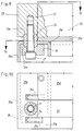
- This locking device R is shown as an enlarged partial area A of FIG. 1 in FIGS. 7 and 8.
- a counter plate 41 is arranged in the area of the latching opening and has a rectangular opening into which a latching element 35 is immersed.
- the locking element 35 has a rectangular element 35a and a rear grip 35b.
- the latching element 35 can first be moved vertically against the force of a spring 45 in a slot 44 and then rotated horizontally will. In the unlocked position shown in FIG. 7, the lever 43 extends transversely to the spray axis.
- the latching element has a rectangular element 35a and a rear grip 35b.
- the cross-sectional shape of the rectangular element 35a matches the latching opening 34a with regard to the cross-sectional shape.
- the final state of which is shown in FIG. 8 the rectangular element 35a is rotated under the counter plate 41, which causes the rear grip 35b to latch with the counter plate 41.
- the latching element 35 dips above the rear grip 35b into the latching opening 34a almost to abut the counter plate 41.
- the latching device R is supported on the support rail 34 via the support area 35c. According to FIG. 7, the entire latching device can subsequently be fastened to the supporting body 37 by means of bolts 46 and retrofitted at the customer's request.
- the injection molding unit is moved back to the "indexing" until an overlap occurs between the rectangular element 35a and the latching opening 34a.
- the piston rods 13a are released from the sleeve carrier on the clamping bolt 21.
- the piston rods are retracted as a result of the process otherwise leading up (Fig. 5).
- pivoting of the injection molding unit on the cross rails 23 as shown in FIG. 6 is possible without risk, for example in order to pull the screw conveyor 42 out of the plasticizing cylinder for cleaning purposes.
- the center of gravity located in the area of the supporting body 37 is approximately above the pivot point P specified by the latching device R.
- the latching opening 34a is also located approximately centrally in the plane of symmetry m-m of the injection molding machine due to the arrangement of the support rail 34.
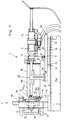
- FIG. 1 also shows the general structure of the injection molding unit.
- the Plasticizing cylinder is surrounded by a protective housing 36 and the injection cylinders E are coaxial with the drive cylinders 13, as is known from the earlier patent application 41 42 927, the disclosure of which is hereby expressly made the subject of the present application. It is precisely this construction of the injection unit that, in conjunction with the appropriately dimensioned sleeve carrier, also enables the application of high forces, as are increasingly required today and in the future due to the constantly increasing demands on the properties of the materials.
Landscapes
- Engineering & Computer Science (AREA)
- Manufacturing & Machinery (AREA)
- Mechanical Engineering (AREA)
- Injection Moulding Of Plastics Or The Like (AREA)
- Moulds For Moulding Plastics Or The Like (AREA)
Abstract
Description
Die Erfindung betrifft eine Kunststoff-Spritzgießmaschine nach dem Oberbegriff des Anspruches 1.The invention relates to a plastic injection molding machine according to the preamble of claim 1.
Eine derartige Spritzgießmaschine ist aus der DE-PS 40 34 577 bekannt. Mit dieser Maschine können wahlweise weitere Spritzgießformen zum Einsatz kommen, deren nichtzentrale Angußöffnungen bei zentralem Formhohlraum unterschiedliche Positionen aufweisen. Unter diesen Voraussetzungen gelangt der plastifizierte Kunststoff beim Einspritzen über einen etwa parallel zur Schließrichtung der Formschließeinheit verlaufenden Angußkanal in den Formhohlraum, welcher Angußkanal am Rand des Formhohlraumes endet. Ein solcher Anguß wird im folgenden als "Parallelanguß" bezeichnet. In dieser Maschine werden in einer horizontalen Ebene liegende Kolbenstangen beweglich in einem Muffenträger geführt, der bei Verschiebung der Spritzgießeinheit passiv mitgeführt wird oder auch für sich manuell verschiebbar ist. Beim Einspritzen des Kunststoffes bewirkt dabei eine dem Anlagedruck des Plastifizierzylinders entgegengesetzte Kraft in den Kolbenstangen eine Arretierung des Muffenträgers an punktförmigen Führungsorganen. Zwar ist die Verbindung der die Kolbenstangen aufnehmenden Muffen über den Muffenträger zum Formträger auf einfache Weise gelöst, jedoch ergibt sich durch den Abstand zwischen dem Angriffspunkt der Kolbenstangen und den Krafteinleitungspunkten der Führungsorgane in den Formträger ein Kraftfeld, das bei größeren Verschiebungen eine seitliche Versetzung der Führungsorgane erfordert, so daß diese Vorrichtung einer automatisierten Verschiebung über die gesamte Breite des Formträgers nicht zugänglich ist.Such an injection molding machine is known from DE-PS 40 34 577. With this machine, additional injection molds can optionally be used, the non-central sprue openings of which have different positions with a central mold cavity. Under these conditions, the plasticized plastic is injected into the mold cavity via a sprue which runs approximately parallel to the closing direction of the mold closing unit and which sprue ends at the edge of the mold cavity. Such a sprue is referred to below as a "parallel sprue". In this machine, piston rods lying in a horizontal plane are movably guided in a sleeve carrier, which is carried along passively when the injection molding unit is displaced or can also be displaced manually. When the plastic is injected, a force in the piston rods that opposes the contact pressure of the plasticizing cylinder locks the sleeve carrier on point-like guide members. Although the connection of the sleeves receiving the piston rods via the sleeve carrier to the mold carrier is solved in a simple manner, the distance between the point of application of the piston rods and the force introduction points of the guide members into the mold carrier results in a force field which, in the event of larger displacements, causes the guide members to be displaced laterally required, so that this device is not accessible for automated displacement across the entire width of the mold carrier.
Aus der DE-PS 38 37 641 ist die Lagerung einer Spritzgießeinheit auf einem die Spritzgießeinheit tragenden gußeisernen Träger bekannt, der auf horizontalen Führungen an zentrale und nichtzentrale Angußöffnungen verschiebbar ist. Die Verschiebung erfolgt über eine aus Wegmeßeinrichtung und Spindeltrieb gebildete, nach Programm betätigbare Verschiebeeinrichtung, die lösbar am Träger befestigt ist. Es läßt sich damit die Spritzgießeinheit genau abstützen und justieren, wobei bewußt eine aufwendige Abstützung in Form des Verschiebetisches in Kauf genommen wird. Problematisch ist in diesem Zusammenhang aber auch, daß der Zugang zur Förderschnecke, insbesondere zu Reinigungszwecken, durch die parallel zur Spritzachse vorgegebene Anordnung der Spritzgießeinheit erschwert ist.DE-PS 38 37 641 the storage of an injection molding unit on a cast iron carrier carrying the injection molding unit is known, which can be moved on horizontal guides to central and non-central sprue openings. The displacement takes place via a displacement device which is formed from a displacement measuring device and a spindle drive and can be actuated according to the program and which is detachably fastened to the carrier. The injection molding unit can thus be precisely supported and adjusted, an elaborate support in the form of the sliding table being consciously accepted. In this context, it is also problematic that access to the screw conveyor, in particular for cleaning purposes, is made more difficult by the arrangement of the injection molding unit that is predetermined parallel to the injection axis.
Ausgehend von diesem Stand der Technik liegt der Erfindung die Aufgabe zugrunde, eine Kunststoff-Spritzgießmaschine der eingangs genannten Gattung derart weiterzubilden, daß eine Verschiebung der Spritzgießeinheit auf kostengünstige und einfache Weise verwirklicht wird, die allen beim Spritzbetrieb auftretenden Anforderungen gerecht wird.Based on this prior art, the invention has for its object to develop a plastic injection molding machine of the type mentioned in such a way that a displacement of the injection molding unit is realized in a cost-effective and simple manner, which meets all the requirements that arise during injection molding.
Diese Aufgabe wird durch die Merkmale des Anspruches 1 gelöst.This object is solved by the features of claim 1.
Durch den verringerten Abstand zwischen Verschiebeeinrichtung und Führungsorganen, in denen die Verschiebung erfolgt, wird die Gefahr von Verkantungen verringert. Die Verschiebung der Spritzgießeinheit erfolgt nur noch am Formträger. Im übrigen Bereich ist die Spritzgießeinheit frei verschieblich gelagert und gleitet auf dem Maschinenfuß. Trotz des somit außermittigen Angriffs der Verschiebeeinrichtung, werden die auftretenden Kräfte sicher bewältigt, so daß das große Moment bei diesem Angriff bewußt in Kauf genommen werden kann. Von selbst ergibt sich dann aber bei jedem Spritzzyklus eine exakte Düsenmitte, da ein selbständiges Einrichten der Spritzgießeinheit während der Arretierbewegung nicht durch den weit vom Zylinderkopf entfernten Verschiebemechanismus behindert wird.The reduced distance between the displacement device and the guide elements in which the displacement takes place reduces the risk of canting. The injection molding unit is only moved on the mold carrier. In the remaining area, the injection molding unit is freely displaceable and slides on the machine base. Despite the eccentric attack of the displacement device, the forces that occur are safely mastered, so that the great moment in this attack can be consciously accepted. Of course, an exact nozzle center then results in each injection cycle, since an independent setup of the injection molding unit during the locking movement is not hindered by the displacement mechanism, which is far away from the cylinder head.
Bei einer Ausgestaltung nach den Ansprüchen 2-3 läßt sich der Muffenträger mitsamt der Spritzeinheit über eine Spindel verschieben. Die Spindel kann bedarfsweise nachgerüstet werden und es besteht auch die Möglichkeit, nach den jeweiligen Anforderungen des Kunden, die Spritzgießeinheit motorisch zu verschieben. Insofern ist es erforderlich, entweder eine Wegmeßeinrichtung, die dem Bediener visuell die Möglichkeit einer Einstellung gibt, oder eine elektronische Wegmeßeinrichtung vorzusehen, die bei einer automatisierten Anlage über den ermittelten Verschiebeweg den die Verschiebung bewirkenden Motor steuert.In a configuration according to claims 2-3, the sleeve carrier together with the injection unit can be moved via a spindle. The spindle can be retrofitted if necessary and there is also the possibility to move the injection molding unit by motor according to the customer's requirements. In this respect, it is necessary to use either a position measuring device, which gives the operator the possibility of a setting visually, or to provide an electronic displacement measuring device which, in an automated system, controls the motor causing the displacement via the determined displacement path.
Weitere Verbesserungen hinsichtlich der Krafteinleitung in den Formträger ergeben sich bei einer Ausgestaltung nach den Ansprüchen 4, 5. Zum einen wird durch eine Führungsschiene gewährleistet, daß die Kraft gleichmäßig auf den Formträger übertragen wird, und eine sichere Führung ist durch eine Führungsnut gewährleistet, in der die Führungsschiene läuft. Da die Krafteinleitung einer dem Anlagedruck des Plastifizierzylinders entgegengesetzten Kraft in den Kolbenstangen auf ein nahezu sich über die gesamte Breite erstreckendes Führungsorgan erfolgt, ergibt sich in jeder Stellung eine kräfteidentische Anbindung. Dadurch ist nicht mehr die Spritzgießeinheit an verschiedenen Punkten am Formträger anzubinden. Die Spritzgießeinheit kann stattdessen in jede beliebige Stellung verschoben werden. Der Kunde kann insbesondere in einem nicht automatisierten Zustand die Spritzgießeinheit in der verschobenen Stellung durch ein Spannelement vorläufig festlegen. Durch die Ausgestaltung eines durch die Führungsnut hervorgerufenen Hintergriffs ist es nämlich möglich, daß durch den Anlagedruck das Spannelement nicht den beim Einspritzen entstehenden hohen Zugkräften unterworfen wird. Eine Arretierung erfolgt in dieser Stellung durch das Anpressen der formseitigen Wandung der Nut an die formseitige Wandung der Führungsschiene.Further improvements with regard to the introduction of force into the mold carrier result in an embodiment according to claims 4, 5. On the one hand, a guide rail ensures that the force is transmitted uniformly to the mold carrier, and reliable guidance is ensured by a guide groove in which the guide rail is running. Since the force in the piston rods, which is opposite to the contact pressure of the plasticizing cylinder, is applied to a guide element that extends almost across the entire width, a connection that is identical to the force results in each position. As a result, the injection molding unit can no longer be connected to the mold carrier at different points. The injection molding unit can instead be moved to any position. In a non-automated state, in particular, the customer can provisionally fix the injection molding unit in the displaced position by means of a clamping element. Because of the design of a rear grip caused by the guide groove, it is in fact possible that the tensioning element is not subjected to the high tensile forces generated during injection by the contact pressure. Locking takes place in this position by pressing the mold-side wall of the groove against the mold-side wall of the guide rail.
Bei einer Ausgestaltung nach Anspruch 6 können beliebig ausgebildete Spritzgießeinheiten, gleichgültig in welcher Lage die Endbereiche der Antriebseinheit angeordnet sind, angekuppelt werden.In an embodiment according to claim 6, arbitrarily designed injection molding units can be coupled, regardless of the position in which the end regions of the drive unit are arranged.
Die Abstützung der Spritzgießeinheit erfolgt bei einer Ausgestaltung nach den Ansprüchen 7-8 dadurch, daß lediglich Schienen aufeinandergleiten. Insofern wird auf aufwendige Verschiebemechanismen verzichtet und die Verschiebeeinrichtung mit den außermittig angreifenden Reibungskräften der Auflage belastet. Die Oberflächenreibung kann durch ein Plasmanitrieren der Reibungsflächen verringert werden, wobei zugleich auch den Erfordernissen eines zuverlässigen Rostschutzes genügt wird. Durch die Flachmaterialien ist auf einfachste Weise ein maßgenaues Abstützen möglich, ohne daß der Maschinenfuß starr auszubilden ist. Nur an ihren Auflagepunkten muß am Maschinenfuß ein Aufwand getrieben werden, um den Anschluß der Schienen an den Maschinenfuß in einer justierbaren Weise zu gewährleisten. Selbst wenn der Maschinenfuß vor Ort ungenau eingerichtet ist, kann durch die Justiermöglichkeit nach Anspruch 8 die gesamte Spritzgießeinheit maßgenau eingestellt werden. Grundsätzlich genügt aber auch eine feste Verbindung der Kreuzschienen mit dem Maschinenfuß, so daß mit der Justierung des Maschinenfußes die Kreuzschienen von selbst miteingerichtet werden.In an embodiment according to claims 7-8, the injection molding unit is supported in that only rails slide on one another. In this respect, elaborate displacement mechanisms are dispensed with and the displacement device is loaded with the frictional forces of the support acting off-center. The surface friction can be reduced by plasma nitriding the friction surfaces, which at the same time also meets the requirements for reliable rust protection. Due to the flat materials, dimensionally accurate support is very easy possible without the machine base being rigid. Only at their support points must an effort be made to ensure the connection of the rails to the machine base in an adjustable manner. Even if the machine base is set up inaccurately on site, the entire injection molding unit can be adjusted precisely by the adjustment option according to claim 8. Basically, however, a fixed connection of the crossbars to the machine base is also sufficient, so that the crossbars are automatically set up by adjusting the machine base.
Durch die Ausbildung eines Schlittens, der auf Schienen gleitet, die nur an den Seitenrändern des Maschinenfußes abgestützt sind, ist der Raum im Maschinenfuß jederzeit zu Wartungszwecken zugänglich. Unter den Schienen können die Abdeckungen des Maschinenfußes unabhängig vom Vorhandensein der Spritzgießeinheit entfernt und die Spritzgießeinheit jeweils auf eine Seite verschoben werden, die einen freien Zugang für das Wartungspersonal ermöglicht. Die nach Anspruch 8 vorgesehenen Schlitze ermöglichen dabei eine einfache Herstellung, da die zur Justierung erforderlichen Widerlager leicht von oben im Maschinenfuß befestigt werden können. Obwohl somit die Spritzgießeinheit beim Verschieben auf unbearbeiteten Maschinenoberflächen gleitet, ergibt sich eine reibungslosere Verschiebemöglichkeit.By designing a slide that slides on rails that are only supported on the side edges of the machine base, the space in the machine base is accessible at all times for maintenance purposes. Under the rails, the covers of the machine base can be removed regardless of the presence of the injection molding unit and the injection molding unit can be moved to one side, which allows free access for the maintenance personnel. The slots provided according to claim 8 enable simple manufacture, since the abutments required for adjustment can easily be attached from above in the machine base. Although the injection molding unit slides on unprocessed machine surfaces when moving, there is a smoother movement.
Werden nach Anspruch 10 die die Antriebseinheit mit dem Schlitten verbindenden Tragelemente als zwei identische Gußkörper ausgebildet, die über Querschienen miteinander verbunden sind, können diese Gußkörper leichter hergestellt werden, da keine aufwendigen Gußformen erforderlich sind und bei Störungen leicht eines dieser Tragelemente ausgetauscht werden kann. Insbesondere wird bei den so geformten Tragelementen die Gefahr von Lunkern gegenüber den bisher bekannten U-förmigen Bügeln verringert.If, according to
Aber auch bei Wartungsarbeiten z.B. an der Förderschnecke oder am Plastifizierzylinder erlaubt die Auflage im hinteren Bereich bei einer Ausgestaltung nach den Ansprüchen 11-12 eine Verbesserung. Bevor die Kolbenstangen vom Muffenträger gelöst sind und nachdem die Spritzgießeinheit zurückgefahren ist, kann sie nämlich am Maschinenfuß abgestützt und abgesichert werden. Der Punkt, an dem die Abstützung erfolgt, dient als Schwenkpunkt für Drehbewegungen, die eine leichte Zugänglichkeit der Förderschnecke gewährleisten. Um insbesondere bei Ausbau von Förderschnecke und/oder Plastifizierzylinder ein Kippen der restlichen Spritzgießeinheit zu vermeiden, wird die Spritzgießeinheit über einen Hebel in dieser Stellung gesichert.But also during maintenance work, for example on the screw conveyor or on the plasticizing cylinder, the support in the rear area allows an improvement in a configuration according to claims 11-12. Before the piston rods are detached from the sleeve carrier and after the injection molding unit has moved back, it can be supported and secured on the machine base. The point at which the support takes place serves as Swivel point for rotary movements that ensure easy access to the screw conveyor. In order to prevent the remaining injection molding unit from tipping over, particularly when removing the screw conveyor and / or plasticizing cylinder, the injection molding unit is secured in this position by means of a lever.
Weitere Vorteile ergeben sich aus den Unteransprüchen. Im folgenden wird die Erfindung anhand der Figuren näher erläutert. Es zeigen:
- Fig. 1
- eine Seitenansicht eines Teils der Spritzgießmaschine, der auf den Formträger der Formschließeinheit und die Spritzgießeinheit beschränkt ist,
- Fig. 2
- einen vergrößerten Ausschnitt von Fig. 1, auf dem die Tragkonstruktion dargestellt ist,
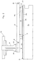
- Fig. 3
- eine Draufsicht auf die Spritzgießmaschine gemäß Fig. 1, bei der zur besseren Klarheit der Darstellung die Spritzgießeinheit bis auf die
Kolbenstangen 13a abgenommen ist, - Fig. 4
- eine Draufsicht auf die Spritzgießmaschine gemäß Fig. 1 in einer seitlich verschobenen Stellung der Spritzgießeinheit,
- Fig. 5
- eine Darstellung gemäß Fig. 4, wobei die Spritzgießeinheit in ihre Mittelstellung verschoben ist und wobei die Kolbenstangen bereits zurückgefahren sind,
- Fig. 6
- eine Darstellung gemäß Fig. 5 mit einer zu Wartungszwecken verschwenkten Spritzgießeinheit,
- Fig. 7, 8
- einen vergrößerten Ausschnitt des Bereiches A von Fig. 1 in einer für die Verschwenkung unverriegelten bzw. verriegelten Stellung des Rastelements,
- Fig. 9
- eine Seitenansicht im Bereich eines Auflagerpunktes der
Kreuzschienen 23, - Fig. 10
- eine Draufsicht auf das Auflager gemäß Fig. 9, teilweise geschnitten gemäß Linie 10-10 von Fig. 9,
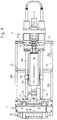
- Fig. 11, 12
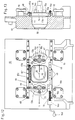
- eine Ansicht des Formträgers bei einem Schnitt nach den Linien 11-11 bzw. 12-12 von Fig. 3,
- Fig. 13
- einen Schnitt durch die Darstellung gemäß Fig. 12 im Bereich einer durch die Spritzachse gelegten vertikalen Ebene,
- Fig. 14
- eine Darstellung gemäß Fig. 12 in einer auf eine nichtzentrale Angußöffnung 30' verschobenen Stellung,
- Fig. 15
- einen vergrößerten Ausschnitt von Fig. 12 im Bereich der Skalierung,
- Fig. 16, 17
- Schnitte nach Linien 16-16 bzw. 17-17 von Fig. 15,
- Fig. 18, 19
- eine den Fign. 12 bzw. 13 entsprechende Darstellung des Formträgers mit einer motorisch angetriebenen Verschiebeeinrichtung.
- Fig. 1
- 2 shows a side view of a part of the injection molding machine which is limited to the mold carrier of the mold clamping unit and the injection molding unit,
- Fig. 2
- 2 shows an enlarged detail from FIG. 1, on which the supporting structure is shown,
- Fig. 3
- 1, in which the injection molding unit is removed except for the
piston rods 13a, for better clarity of the illustration, - Fig. 4
- 2 shows a top view of the injection molding machine according to FIG. 1 in a laterally displaced position of the injection molding unit,
- Fig. 5
- 4, wherein the injection molding unit is shifted to its central position and the piston rods have already been retracted,
- Fig. 6
- 5 with an injection molding unit pivoted for maintenance purposes,
- 7, 8
- 2 shows an enlarged section of area A from FIG. 1 in a position of the latching element that is unlocked or locked for pivoting,
- Fig. 9
- a side view in the region of a support point of the cross rails 23,
- Fig. 10
- 9, a partial section along line 10-10 of FIG. 9,
- 11, 12
- 3 shows a view of the mold carrier in a section along lines 11-11 or 12-12 of FIG. 3,
- Fig. 13
- 12 shows a section through the representation according to FIG. 12 in the region of a vertical plane through the spray axis,
- Fig. 14
- 12 in a position shifted to a non-central sprue opening 30 ',
- Fig. 15
- 12 shows an enlarged detail of FIG. 12 in the area of scaling,
- 16, 17
- Cuts along lines 16-16 and 17-17 of Fig. 15,
- 18, 19
- one the fig. 12 and 13 corresponding representation of the mold carrier with a motor-driven displacement device.
Der stationäre Formträger 10 ist Bestandteil der horizontal schließenden Formschließeinheit F einer Kunststoffspritzgießmaschine, die mit einer horizontal einspritzenden Spritzgießeinheit S versehen ist. Auf dem Formträger 10 ist eine erste Spritzgießform 31 (Fig. 12) mit zentraler Angußöffnung 30 und zentralem Formhohlraum 32 aufspannbar. Wahlweise sind auf den Formträger 10 verschiedene weitere Spritzgießformen 31' (Fig. 14) mit nichtzentraler Angußöffnung 30' und zentralem Formhohlraum 32' aufspannbar. In die Spritzgießformen 31, 31' kann plastifiziertes Kunststoffmaterial oder vergleichbares Material, das für die Herstellung von Teilen auf Kunststoff-Spritzgießmaschinen geeignet ist, wie z.B. keramisches Material durch eine mittels einer Verschiebeeinrichtung quer zu ihrer Spritzachse s-s in horizontaler Richtung verschiebbare Spritzgießeinheit S eingespritzt werden. Die Einspritzung erfolgt dabei nach einer parallelen Verschiebung der Spritzgießeinheit im Parallelanguß.The
Der Formträger 10 weist eine, etwa symmetrisch zu seiner horizontalen Symmetrieebene y-y (Fig. 11) angeordnete, in Verschieberichtung vergrösserte Durchtrittsöffnung 11 für den Plastifizierzylinder 12 auf. Der Plastifizierzylinder ist mittels hydraulicher Antriebszylinder an die jeweils eingespannte Spritzgießform 31, 31' anlegbar. Als Antriebseinheit können jedoch auch andere Antriebe, wie elektromechanische oder pneumatische Antriebe eingesetzt werden. Die Kolbenstangen 13a der Antriebszylinder 13 erstrecken sich bis zum Formträger 10 und bilden Endbereiche der Antriebseinheit. Beim Verschieben der Spritzgießeinheit S sind die freien Enden 13b in Aufnahmen wenigstens eines in den Führungsorganen verschiebbaren Aufnahmenträgers aufgenommen. Als Aufnahmen werden dabei Muffen 14 verwendet. Der Aufnahmenträger wird im folgenden als Muffenträger 15 bezeichnet. Der Muffenträger 15 weist zwischen seinen als Muffen ausgebildeten Aufnahmen eine Ausnehmung 15a für den Durchtritt des Plastifizierzylinders auf. Über den Muffenträger 15 sind die Kolbenstangen in Führungsorganen des Formträgers 10 mittelbar geführt. Diese Führungsorgane liegen außerhalb der Durchtrittsöffnung 11, z. B. oberhalb und unterhalb der Durchtrittsöffnung. Der Muffenträger überträgt somit die während des Spritzbetriebs von den Kolbenstangen 13a übertragenen Kräfte über die Führungsorgane auf den Formträger 10. Wie aus Fig. 12 und 14 ersichtlich, überdeckt der Muffenträger 15 in seinen beiden extremen, einander entgegengesetzten Verschiebepositionen die Durchtrittsöffnung 11 je etwa hälftig. Während des Spritzbetriebs sind die Kolbenstangen axial in ihrer Position am Muffenträger 15 festgelegt.The
Die Verschiebung des Muffenträgers 15 erfolgt über eine Verschiebeeinrichtung, die im konkreten Ausführungsbeispiel als Spindeltrieb 16 ausgebildet ist, dessen stationärer Teil am Formträger und dessen beweglicher Teil am als Aufnahmenträger ausgebildeten Muffenträger 15 angeordnet ist. Andere Anordnungen der Verschiebeeinrichtung sind in diesem Bereich möglich, der Formträger, Muffenträger oder die Endbereiche der Antriebseinheit umfaßt. Im übrigen ist die Spritzgießeinheit zumindest in Verschieberichtung frei verschieblich auf dem Maschinenfuß abgestützt. Der Spindeltrieb kann entbeim weder wie beim Ausführungsbeispiel der Fign. 11-14 manuell über eine Kurbel 16d betätigt oder wie beim Ausführungsbeispiel der Fign. 18 und 19 über einen beispielsweise elektrisch oder hydraulisch betriebenen Motor 16f angetrieben werden. Das Spindeldrehlager 16a ist dabei am Formträger angeordnet, während die Mutter 16b dem Muffenträger 15 zugeordnet ist. Um. Schwierigkeiten, wie z. B. Verschmutzungen der Gewindespindel 16e vorzubeugen, ist diese im Bereich zwischen den beiden Kolbenstangen 13a durch eine Spindelhülse 16c geschützt.The
Muffenträger 15 und Formträger 10 sind Wegmeßeinrichtungen zugeordnet, deren beweglicher Teil am Muffenträger 15 in Nachbarschaft der Führungsorgane und deren stationärer Teil am Formträger 10 an den Führungsorganen angeordnet ist. Die Maschine kann zunächst in einer Variante ausgeliefert werden, die für den nachträglichen Einsatz der Verschiebeeinrichtung bereits vorbereitet ist. Ganz nach den jeweiligen Bedürfnissen des Kunden kann eine Nachrüstung oder von vornherein eine Auslieferung mit dem motorisch betätigten Spindeltrieb erfolgen. Erfolgt eine motorische Verschiebung, so wird als Wegmeßeinrichtung 17 ein Linearpotentiometer vorgesehen, dessen Gehäuse 17a am Formträger 10 befestigt ist und dessen Schleifkontaktträger 17b mit dem Muffenträger verbunden ist. Die Wegmeßeinrichtung 17 liefert dabei einer Steuereinrichtung Signale, wie weit bereits die Spritzgießeinheit verschoben ist, so daß durch einen Soll-Ist-Wert-Vergleich eine genaue Einstellung der Spritzgießmaschine erfolgen kann. Bei manueller Verschiebung genügt als Wegmeßeinrichtung 17' eine Skalierung 17c am Muffenträger und ein Zeiger 17d an der als Führungsorgan ausgebildeten Führungsschiene 18.
Um eine Verschiebung möglichst über den gesamten gewünschten Bereich zu verwiklichen, erstreckt sich die Führungsschiene 18 nahezu über die gesamte Breite des Formträgers. Die Führungsschiene 18 ist mittels Bolzen 48 unmittelbar mit einer Anformung 10a des Formträgers 10 verbunden. Die Kolbenstangen 13a liegen in der horizontalen Symmetrieebene y-y des Formträgers 10 und sind in den Führungsschienen 18 über nahezu die gesamte Breite des Formträgers, zumindest aber im Bereich der Muffen 14 geführt. Durch die Vielzahl der die Führungsschienen 18 befestigenden Bolzen 48 wird in jeder Stellung der Spritzgießeinheit eine weitgehend identische Kräfteeinleitung verwirklicht.In order to make shifting as possible as possible over the entire desired area, the
Der Muffenträger besitzt oben und unten eine Führungsnut 15b, in die die Führungsschiene 18 eintaucht. Der beim Verschieben mit Spiel verschiebbare Muffenträger 15 kann durch wenigstens ein Spannelement 19 (Fig. 11) an der Führungsschiene 18 festgelegt werden. Beim Einspritzen des Materials in den Formhohlraum 32 führt der entstehende Anlagedruck des Plastifizierzylinders 12 zu einer entgegengesetzten Zugkraft in den Kolbenstangen, die über die formseitige Wandung der Nut 15b (Fig. 17) des Muffenträgers 15 auf die formseitige Wandung der Führungsschiene 18 großflächig übertragen wird. Bei Verspannung mittels Spannelement 19 wird der Muffenträger 15 bereits durch den Spannbolzen 49 in Richtung der Zugkraft gezogen. Diese Spannkraft ist jedoch geringer als die beim Einspritzen entstehende Zugkraft. Aufgrund der Anordnung des Spannbolzens auf der vom Formträger abgewandten Seite wird dieser jedoch nicht der vollen Zugkraft unterworfen. Stattdessen wird beim Einspritzen die Spannkraft im Spannbolzen 49 verringert.The sleeve carrier has a
Am Muffenträger 15 selbst sind die als Endbereiche der Antriebseinheit ausgebildeten Kolbenstangen 13a in den Muffen durch Spannbolzen 21 gehalten, die an den Spannflächen 13c der Kolbenstangen angreifen. Die Muffen sind entweder am Muffenträger 15 unmittelbar angeformt oder über Muffenelemente 14a am Muffenträger befestigt. Die Muffenelemente 14a sind dabei über Spannbolzen 47 mit dem Muffenträger 15 verbunden. Verschiedene Paare von Muffenelementen mit angeformten Muffen können alternativ auf den plangeschliffenen Spannflächen 15c des Muffenträgers 15 aufgespannt werden. Die einzelnen Muffenelemente 14a unterscheiden sich durch einen unterschiedlichen gegenseitigen Abstand und/oder eine unterschiedliche lichte Weite ihrer Muffen. Dadurch können verschiedenste Spritzgießeinheiten an dem Muffenträger befestigt werden. Wie im Stand der Technik bekannt, können auch zwei Muffenträger vorgezusehen werden, die jeweils nur eine Kolbenstange aufnehmen.On the
Die freie Verschiebbarkeit der Spritzgießeinheit in vom Formträger abgewandten Bereich erfolgt dadurch, daß die Spritzgießeinheit beim Verschieben mittels einem sie tragenden, in Spritzrichtung angeordneten Schienenpaar 22 auf quer zur Spritzachse angeordneten Schienen gleitet. Diese Schienen werden aufgrund ihrer kreuzförmigen Anordnung, wie sie sich insbesondere aus der Draufsicht gemäß Fig. 3 ergibt, im folgenden als Kreuzschienen bezeichnet. Die beiden Kreuzschienen 23 sind auf vier fein bearbeiteten Auflagern am Maschinenfuß 25 abgestützt und überbrücken im übrigen den gesamten Maschinenfuß (Fig. 11). Die Ausbildung eines solchen Auflagerbereiches ergibt sich aus den Fign. 9, 10. Grundsätzlich befindet sich das Auflager 24 für die Kreuzschienen nach den Fign. 10, 11 am umgebördelten Längsrand 25b der Seitenwände 25a des Maschinenfußes 25. Am Längsrand 25b sind an jedem Auflager zwei Schlitze 25c vorgesehen, über die ein Widerlagerblock 26 am Maschinenfuß von oben angeschweißt werden kann. Dieser Widerlagerblock 26 dient einer zentrierten Schraube 27 als Widerlager. Zwischen den beiden Schlitzen 25c ist eine Öffnung vorgesehen, die die Schraube 27 und ein als Auflager 24 dienendes Zentrierstück koaxial aufnimmt. Das Zentrierstück ist sowohl am Widerlagerblock als auch an der Kreuzschiene 23 jeweils in Ausnehmungen 23a, 26a gelagert. Da an diesen Auflagerpunkten auch eine Justierung der Kreuzschienen 23 erfolgen kann, um von der Aufstellgenauigkeit und der Steifheit des Maschinenfußes 25 unabhängig zu sein, kann die Schraube 27 grundsätzlich auch als Justierschraube ausgebildet sein. In diesem Fall ist die Schraube 27 von unten zugänglich, und bedarfsweise können auch Durchgriffsöffnungen im Maschinenfuß vorgesehen werden, um eine Zugänglichkeit der Schraube zu erleichtern. Die Kreuzschienen 23 können aber auch vom Hersteller mit dem Maschinenfuß so verbunden werden, daß sie sich beim Einrichten des Maschinenfußes vor Ort selbstständig einrichten.The free displacement of the injection molding unit in the area facing away from the mold carrier is achieved in that the injection molding unit slides on rails arranged transversely to the injection axis during the displacement by means of a pair of
Wie sich aus den Darstellungen gemäß Fig. 2 und 3 ergibt, wird die gesamte Spritzgießeinheit von einem Schienenpaar 22 getragen, das über zwei Querstangen 28 zu einem Schlitten verbunden ist. Stirnseitig trägt dieser Schlitten Tragelemente 29 für die Antriebszylinder 13. Wie sich aus Fig. 11 ergibt, sind die Tragelemente über Verbindungsbolzen 38, 39 mit dem Schienenpaar 22 verbunden. Bei den Tragelementen handelt es sich um zwei identische Tragelemente von denen jeweils eines jeweils einer Kolbenstange 13a des Antriebszylinders 13 zugeordnet ist. In Fig. 4 sind die beiden Tragelemente spiegelsymmetrisch zu einer durch die Spritzachse s-s gehenden vertikalen Ebene angeordnet. Es handelt sich um Gußkörper, die im Bereich der Kolbenstangen 13a als radial gespaltene Spannmuffen 29a (Fig. 11) ausgebildet sind und mittels die Spaltfugen durchsetzende Spannbolzen 33 mit einem Spannstück 29b zur Verklemmung der Kolbenstangen 13a verbunden sind.2 and 3, the entire injection molding unit is carried by a pair of
Die Kreuzschienen 23 sind über eine Stützschiene 34 miteinander verbunden, die eine Rastöffnung 34a besitzt, in der die Spritzgießeinheit S mittels einer Rasteinrichtung R verrastbar ist. Diese Rasteinrichtung R ist als vergrößerter Teilbereich A von Fig. 1 in den Fign. 7 und 8 dargestellt. Im Bereich der Rastöffnung ist eine Gegenplatte 41 angeordnet, die eine rechteckige Öffnung aufweist, in die ein Rastelement 35 eintaucht. Das Rastelement 35 besitzt ein Rechteckelement 35a und einen Hintergriff 35b. Über einen Hebel 43 kann das Rastelement 35 gegen die Kraft einer Feder 45 in einem Schlitz 44 zunächst vertikal bewegt und dann horizontal gedreht werden. In der unverriegelten Stellung gemäß Fig. 7 erstreckt sich der Hebel 43 quer zur Spritzachse. Das Rastelement besitzt ein Rechteckelement 35a sowie einen Hintergriff 35b. Bei der vertikalen Bewegung des Hebels 43 stimmt die Querschnittsform des Rechteckelements 35a mit der Rastöffnung 34a hinsichtlich der Querschnittsform überein. Bei der anschließend erfolgenden Drehbewegung, deren Endzustand in Fig. 8 dargestellt ist, wird das Rechteckelement 35a unter die Gegenplatte 41 gedreht, was zu einem Verrasten des Hintergriffs 35b mit der Gegenplatte 41 führt. Das Rastelement 35 taucht oberhalb des Hintergriffs 35b in die Rastöffnung 34a bis nahezu zum Anliegen an die Gegenplatte 41 ein. Die Rasteinrichtung R stützt sich über den Auflagebereich 35c an der Stützschiene 34 ab. Gemäß Fig. 7 kann die gesamte Rasteinrichtung nachträglich mittels Bolzen 46 am Tragkörper 37 befestigt und auf Wunsch des Kunden nachgerüstet werden.The cross rails 23 are connected to one another via a
Zur Verrastung wird die Spritzgießeinheit bis zur "Indexierung" zurückgefahren, bis eine Überdeckung zwischen Rechteckelement 35a und Rastöffnung 34a eintritt. Nach der Verrastung werden die Kolbenstangen 13a vom Muffenträger an den Spannbolzen 21 gelöst. Durch den sonst das Vorfahren bewirkenden Vorgang werden die Kolbenstangen zurückgefahren (Fig. 5). In der indexierten Stellung ist gefahrlos eine Verschwenkung der Spritzgießeinheit auf den Kreuzschienen 23 wie in Fig. 6 dargestellt möglich, um beispielsweise die Förderschnecke 42 zu Reinigungszwecken aus dem Plastifizierzylinder herauszuziehen. Bei dieser Verschwenkung befindet sich der im Bereich des Tragkörpers 37 liegende Schwerpunkt ungefähr über dem von der Rasteinrichtung R vorgegebenen Schwenkpunkt P. Die Rastöffnung 34a ihrerseits befindet sich aber aufgrund der Anordnung der Stützschiene 34 ebenfalls ungefähr mittig in der Symmetrieebene m-m der Spritzgießmaschine.For latching, the injection molding unit is moved back to the "indexing" until an overlap occurs between the rectangular element 35a and the latching opening 34a. After the locking, the
Trotz allem sind die Innenräume des Maschinenfußes 25 über die Abdeckplatten 25d, wie aus den Fign. 2, 9, 11 ersichtlich, jederzeit zugänglich, da die Abdeckplatten 25d unter den Kreuzschienen bedarfsweise herausgezogen werden können. Je nachdem auf welcher Seite der Spritzgießmaschine eine Wartung im Innenraum des Maschinenfußes erforderlich ist, kann die Spritzgießeinheit so verschoben werden, daß eine freie Zugänglichkeit ohne Behinderung durch die Spritzgießeinheit S möglich ist. Schließlich ergibt sich aus Fig. 1 auch der generelle Aufbau der Spritzgießeinheit. Der Plastifizierzylinder ist von einem Schutzgehäuse 36 umgeben und die Einspritzzylinder E liegen koaxial mit den Antriebszylindern 13, wie dies aus der älteren Patentanmeldung 41 42 927 bekannt ist, deren Offenbarungsgehalt hiermit ausdrücklich zum Gegenstand auch der vorliegenden Anmeldung gemacht wird. Gerade dieser Aufbau des Spritzaggregates ermöglicht nämlich in Verbindung mit dem entsprechend dimensionierten Muffenträger auch das Aufbringen hoher Kräfte, wie sie aufgrund der ständig wachsenden Anforderungen an die Eigenschaften der Materialien heute und in Zukunft immer mehr erforderlich sind.In spite of everything, the interiors of the
Claims (12)
- Plastics material injection moulding machine, including a mould closing unit (F) and a horizontally injecting injection moulding unit (S), which is displaceable, as required, by means of a displacement device transversely relative to its injection axis (s-s) over the respective sprue openings (30, 30') of first injection moulds (31), which are clampable on the stationary mould carrier (10) of the mould closing unit (F) and have a central sprue opening (30), and selectively of additional injection moulds (31') having a non-central sprue opening (30'), into which plasticised material in the parallel sprue is injectable, the mould carrier (10) having an opening (11) for the plasticising cylinder (12) of the injection moulding unit (S), which is attachable to the injection mould (31, 31') by at least one drive unit, said opening being enlarged when viewed with respect to the direction of displacement, and the plastics material injection moulding machine also including guide means for end regions of the drive unit, which end regions extend to the mould carrier (10) and are guided in the direction of displacement during the displacement of the injection moulding unit (S), the free ends (13b) of said end regions being accommodated in receivers of at least one receiver carrier, which is displaceable in the guide means and has space for the plasticising cylinder (12) to pass therethrough, characterised in that the displacement device co-operates with the mould carrier (10) and in the region of the receiver carrier, and in that the injection moulding unit (S) is freely displaceable at least in the direction of displacement.
- Injection moulding machine according to claim 1, characterised in that a spindle drive (16) is provided as the displacement device for the injection moulding unit (S), the stationary spindle pivot bearing of said spindle drive being provided on the mould carrier (10), and the ball rolling nut of said spindle drive being provided as a movable part of the displacement device on the bushing support (15), which is configured as a receiver carrier.
- Injection moulding machine according to claim 1 or 2, characterised in that a distance measuring device (17, 17') is associated with a bushing support (15), configured as a receiver carrier, and with the mould carrier (10), the movable part of said distance measuring device being disposed on the bushing support (15) in the vicinity of the guide means, and the stationary part of said distance measuring device being disposed on the mould carrier (10) on the guide means.
- Injection moulding machine according to one of the preceding claims, characterised in that the end regions are formed by piston rods (13a) of hydraulic drive cylinders (13), which are configured as a drive unit and are disposed in the horizontal plane of symmetry (y-y) of the mould carrier (10), and are guided in guide bars (18), which are configured as a guide means and mounted on the mould carrier (10), over virtually the entire width of the mould carrier, at least in the region of the bushings (14), which are configured as receivers, and in that means are provided for the axial securement of the piston rods (13a) in their respective positions.
- Injection moulding machine according to one of the preceding claims, characterised in that the receiver carrier has a guide groove (15b) at its upper and lower ends, and the guide bar (18) drops into said groove, and in that the receiver carrier (15), which is displaceable with some clearance during the displacement movement, is securable on the guide bar (18) by means of clamping elements (19) and is securable in its position in the direction of the injection axis (s-s) by being clamped to the guide bars (18) on the side of the guide bar (18) remote from the clamping element (19).
- Injection moulding machine according to one of the preceding claims, characterised in that a first pair of bushing elements (14a), provided with bushings (14) formed to fit thereon, and at least an additional pair of bushing elements, provided with bushings formed to fit thereon, are alternatively clampable onto surface-ground clamping faces (15c) of the bushing support (15) by means of clamping bolts (21), the bushing elements (14a) of the two pairs differing from one another because their bushings have different spacings therebetween and/or have a different inside width.
- Injection moulding machine according to one of the preceding claims, characterised in that, during the displacement movement, a pair of rods (22), which carries the injection moulding unit (S) and is disposed in the injection direction, slides on bars (cross-bars 23), which are disposed transversely relative to the injection axis and are supported on the machine base on finely machined bearings (24).
- Injection moulding machine according to claim 7, characterised in that the bearings (24) are provided on the flanged longitudinal edge (25b) of the lateral walls (25a) of the machine base (25), in which an abutment block (26) is welded from above beneath the longitudinal edge (25b) through two slots (25c), which block serves as an abutment for a screw (27), which is centred on the abutment block (26), for the cross-bars (23), and said screw is configured as an adjustment screw.
- Injection moulding machine according to claim 7 or 8, characterised in that the pair of rods (22) is connected by two cross-bars (28) to form a slide which has, on its end face, supporting members (29) for the drive unit (13).
- Injection moulding machine according to claim 9, characterised in that the supporting members (29) are formed from two identical castings, which are disposed in a mirror-symmetrical manner relative to a vertical plane extending through the injection axis (s-s), said castings being configured as radially split tensioning bushings (29a) in the region of the end regions of the drive unit and being clampable to the end regions by means of clamping bolts (33) traversing the split joints.
- Injection moulding machine according to one of claims 7-10, characterised in that the cross-bars (23) are interconnected via a supporting bar (34), which has a locking aperture (34a) in which the injection moulding unit (S) is lockable.
- Injection moulding machine according to claim 11, characterised in that the supporting bar (34), disposed in the plane of symmetry (m-m) of the injection moulding machine, accommodates in the locking aperture (34a) a locking element (35) of the returned injection moulding unit (S), and in that the locking aperture serves as a pivot point (P) for a pivotal movement of the injection moulding unit (S), and in that, once the locking has been effected, the piston rods (13a) of the drive cylinders released from the bushings (14) are withdrawable.
Applications Claiming Priority (2)
| Application Number | Priority Date | Filing Date | Title |
|---|---|---|---|
| DE4227336 | 1992-08-18 | ||
| DE4227336A DE4227336C1 (en) | 1992-08-18 | 1992-08-18 | Plastic injection molding machine |
Publications (2)
| Publication Number | Publication Date |
|---|---|
| EP0583718A1 EP0583718A1 (en) | 1994-02-23 |
| EP0583718B1 true EP0583718B1 (en) | 1996-07-03 |
Family
ID=6465816
Family Applications (1)
| Application Number | Title | Priority Date | Filing Date |
|---|---|---|---|
| EP93112775A Expired - Lifetime EP0583718B1 (en) | 1992-08-18 | 1993-08-10 | Plastic injection moulding machine |
Country Status (6)
| Country | Link |
|---|---|
| US (1) | US5360332A (en) |
| EP (1) | EP0583718B1 (en) |
| JP (1) | JPH0767708B2 (en) |
| AT (1) | ATE139929T1 (en) |
| CA (1) | CA2101768C (en) |
| DE (2) | DE4227336C1 (en) |
Families Citing this family (9)
| Publication number | Priority date | Publication date | Assignee | Title |
|---|---|---|---|---|
| DE19531326C1 (en) * | 1995-08-25 | 1996-08-22 | Karl Hehl | Compact injection unit for plastics injection machine |
| JPH11511082A (en) * | 1995-08-25 | 1999-09-28 | ヘール、カルル | Injection molding unit of synthetic resin injection molding machine |
| DE19949958C2 (en) * | 1999-10-16 | 2003-10-02 | Karl Hehl | Injection molding machine with a protective cover |
| US7393199B2 (en) * | 2000-04-06 | 2008-07-01 | Mgs Mfg. Group, Inc. | Multi-shot injection molding arrangement |
| US6994810B2 (en) * | 2000-04-06 | 2006-02-07 | Mgs Mfg. Group, Inc. | Multi-shot injection molding arrangement |
| US20020110618A1 (en) * | 2000-06-12 | 2002-08-15 | Lang-Fu Tsai | Apparatus having a moving mold clamping seat for high temperature fluid injection molding |
| US6572362B2 (en) * | 2001-08-01 | 2003-06-03 | The Goodyear Tire & Rubber Company | Apparatus for injection molding in alternate planes |
| WO2005023507A1 (en) * | 2003-09-09 | 2005-03-17 | Netstal-Maschinen Ag | Injection unit, and method for the adjustment thereof |
| CN108367472B (en) | 2015-11-06 | 2021-06-01 | 马斯特模具(2007)有限公司 | Injection unit positioning device |
Family Cites Families (9)
| Publication number | Priority date | Publication date | Assignee | Title |
|---|---|---|---|---|
| DE3683181D1 (en) * | 1985-04-15 | 1992-02-13 | Karl Hehl | INJECTION MOLDING MACHINE FOR PLASTICS. |
| JPH0325948Y2 (en) * | 1985-09-09 | 1991-06-05 | ||
| DE3722228A1 (en) * | 1987-05-11 | 1988-12-01 | Karl Hehl | PLASTIC INJECTION MOLDING MACHINE WITH AN INJECTABLE INJECTION MOLDING UNIT |
| DE3725220A1 (en) * | 1987-07-30 | 1989-02-16 | Karl Hehl | PLASTIC INJECTION MOLDING MACHINE WITH AN INJECTION UNIT TRANSFERABLE IN DIFFERENT WORKING SETTINGS |
| CA1328158C (en) * | 1988-05-11 | 1994-04-05 | Toshiyuki Kanai | Multi-injection molded body, a method of molding for the same, and a multi-injection molding machine |
| CA2001342C (en) * | 1988-11-05 | 1994-04-05 | Karl Hehl | Injection molding machine |
| DE3837641A1 (en) * | 1988-11-05 | 1990-05-10 | Karl Hehl | Plastics injection-moulding machine |
| US5219586A (en) * | 1989-02-13 | 1993-06-15 | The Japan Steel Works Ltd. | Apparatus for both single and double injection molding |
| DE4034577C1 (en) * | 1990-10-31 | 1992-01-30 | Karl 7298 Lossburg De Hehl |
-
1992
- 1992-08-18 DE DE4227336A patent/DE4227336C1/en not_active Expired - Fee Related
-
1993
- 1993-08-02 CA CA002101768A patent/CA2101768C/en not_active Expired - Fee Related
- 1993-08-10 EP EP93112775A patent/EP0583718B1/en not_active Expired - Lifetime
- 1993-08-10 DE DE59303119T patent/DE59303119D1/en not_active Expired - Fee Related
- 1993-08-10 AT AT93112775T patent/ATE139929T1/en not_active IP Right Cessation
- 1993-08-17 US US08/107,371 patent/US5360332A/en not_active Expired - Fee Related
- 1993-08-18 JP JP5223910A patent/JPH0767708B2/en not_active Expired - Fee Related
Also Published As
| Publication number | Publication date |
|---|---|
| DE59303119D1 (en) | 1996-08-08 |
| CA2101768A1 (en) | 1994-02-19 |
| DE4227336C1 (en) | 1994-03-31 |
| CA2101768C (en) | 2001-07-31 |
| US5360332A (en) | 1994-11-01 |
| JPH06210661A (en) | 1994-08-02 |
| ATE139929T1 (en) | 1996-07-15 |
| EP0583718A1 (en) | 1994-02-23 |
| JPH0767708B2 (en) | 1995-07-26 |
Similar Documents
| Publication | Publication Date | Title |
|---|---|---|
| EP0895848B1 (en) | Device for producing injection moulded articles from at least two plastic melts | |
| EP0585664B1 (en) | Plastic injection moulding machine | |
| EP0311133A1 (en) | Injection moulding machine | |
| EP0368149B1 (en) | Plastic injection-moulding machine | |
| DE3720214A1 (en) | INJECTION MOLDING MACHINE | |
| EP1802441B1 (en) | Closing unit for an injection moulding machine comprising a stack mould | |
| EP0583718B1 (en) | Plastic injection moulding machine | |
| DE3501000A1 (en) | TOOL INSTALLATION AND CLAMPING DEVICE ON AN INJECTION MOLDING MACHINE | |
| EP0291008B1 (en) | Plastic injection-moulding machine with an injection unit movable into different working positions | |
| DE3038160A1 (en) | INJECTION MOLDING DEVICE | |
| DE2214646C3 (en) | Plastic injection molding machine with a mold clamping device with a rectangular base body | |
| DE69901369T2 (en) | Device for the production of foamed plastic parts | |
| EP3664986A1 (en) | Mounting device for mould parts of an injection-moulding tool, injection-moulding tool and injection-moulding machine | |
| WO1997012741A2 (en) | Mould closure unit with a device for removing injection mouldings | |
| DE19535081A1 (en) | Two-platen injection moulding machine with positioning drive and guides below mould assembly area | |
| DE1938171C3 (en) | Device for producing molded parts from foamable plastic | |
| EP3959058B1 (en) | Injection molding unit for an injection molding machine for processing plastics | |
| EP3787868B1 (en) | Cold runner block | |
| DE2020061B2 (en) | Mold closing unit for the injection mold of an injection molding machine with protective slides | |
| EP0322754B1 (en) | Protecting cover for a plastic-injection-moulding machine | |
| EP3015242B1 (en) | Injection moulding machine | |
| DE10214466A1 (en) | Injection molding machine with injection units for fixed and for moving tool part has latter injection units mounted at an acute angle and away from machine axis | |
| EP0599406A1 (en) | Injection moulding or injection compression moulding machine | |
| DE2027509C (en) | Mold closing device, in particular for die casting and injection molding machines for metals and plastics | |
| DE2112310A1 (en) | Injection mould assembly - for horizontal or vertical mounting and different injection directions |
Legal Events
| Date | Code | Title | Description |
|---|---|---|---|
| PUAI | Public reference made under article 153(3) epc to a published international application that has entered the european phase |
Free format text: ORIGINAL CODE: 0009012 |
|
| AK | Designated contracting states |
Kind code of ref document: A1 Designated state(s): AT CH DE ES FR GB IT LI NL |
|
| 17P | Request for examination filed |
Effective date: 19940729 |
|
| 17Q | First examination report despatched |
Effective date: 19950831 |
|
| GRAH | Despatch of communication of intention to grant a patent |
Free format text: ORIGINAL CODE: EPIDOS IGRA |
|
| GRAH | Despatch of communication of intention to grant a patent |
Free format text: ORIGINAL CODE: EPIDOS IGRA |
|
| GRAA | (expected) grant |
Free format text: ORIGINAL CODE: 0009210 |
|
| AK | Designated contracting states |
Kind code of ref document: B1 Designated state(s): AT CH DE ES FR GB IT LI NL |
|
| PG25 | Lapsed in a contracting state [announced via postgrant information from national office to epo] |
Ref country code: NL Free format text: LAPSE BECAUSE OF FAILURE TO SUBMIT A TRANSLATION OF THE DESCRIPTION OR TO PAY THE FEE WITHIN THE PRESCRIBED TIME-LIMIT Effective date: 19960703 Ref country code: ES Free format text: THE PATENT HAS BEEN ANNULLED BY A DECISION OF A NATIONAL AUTHORITY Effective date: 19960703 |
|
| REF | Corresponds to: |
Ref document number: 139929 Country of ref document: AT Date of ref document: 19960715 Kind code of ref document: T |
|
| REG | Reference to a national code |
Ref country code: CH Ref legal event code: NV Representative=s name: PATENTANWALTSBUREAU BOSSHARD UND LUCHS |
|
| ET | Fr: translation filed | ||
| REF | Corresponds to: |
Ref document number: 59303119 Country of ref document: DE Date of ref document: 19960808 |
|
| GBT | Gb: translation of ep patent filed (gb section 77(6)(a)/1977) |
Effective date: 19960816 |
|
| ITF | It: translation for a ep patent filed | ||
| NLV1 | Nl: lapsed or annulled due to failure to fulfill the requirements of art. 29p and 29m of the patents act | ||
| PLBE | No opposition filed within time limit |
Free format text: ORIGINAL CODE: 0009261 |
|
| STAA | Information on the status of an ep patent application or granted ep patent |
Free format text: STATUS: NO OPPOSITION FILED WITHIN TIME LIMIT |
|
| 26N | No opposition filed | ||
| PGFP | Annual fee paid to national office [announced via postgrant information from national office to epo] |
Ref country code: GB Payment date: 20010719 Year of fee payment: 9 |
|
| PGFP | Annual fee paid to national office [announced via postgrant information from national office to epo] |
Ref country code: CH Payment date: 20010824 Year of fee payment: 9 Ref country code: AT Payment date: 20010824 Year of fee payment: 9 |
|
| REG | Reference to a national code |
Ref country code: GB Ref legal event code: IF02 |
|
| PG25 | Lapsed in a contracting state [announced via postgrant information from national office to epo] |
Ref country code: GB Free format text: LAPSE BECAUSE OF NON-PAYMENT OF DUE FEES Effective date: 20020810 Ref country code: AT Free format text: LAPSE BECAUSE OF NON-PAYMENT OF DUE FEES Effective date: 20020810 |
|
| PG25 | Lapsed in a contracting state [announced via postgrant information from national office to epo] |
Ref country code: LI Free format text: LAPSE BECAUSE OF NON-PAYMENT OF DUE FEES Effective date: 20020831 Ref country code: CH Free format text: LAPSE BECAUSE OF NON-PAYMENT OF DUE FEES Effective date: 20020831 |
|
| GBPC | Gb: european patent ceased through non-payment of renewal fee |
Effective date: 20020810 |
|
| REG | Reference to a national code |
Ref country code: CH Ref legal event code: PL |
|
| PGFP | Annual fee paid to national office [announced via postgrant information from national office to epo] |
Ref country code: FR Payment date: 20030819 Year of fee payment: 11 |
|
| PG25 | Lapsed in a contracting state [announced via postgrant information from national office to epo] |
Ref country code: FR Free format text: LAPSE BECAUSE OF NON-PAYMENT OF DUE FEES Effective date: 20050429 |
|
| REG | Reference to a national code |
Ref country code: FR Ref legal event code: ST |
|
| PGFP | Annual fee paid to national office [announced via postgrant information from national office to epo] |
Ref country code: DE Payment date: 20080614 Year of fee payment: 16 |
|
| PGFP | Annual fee paid to national office [announced via postgrant information from national office to epo] |
Ref country code: IT Payment date: 20080826 Year of fee payment: 16 |
|
| PG25 | Lapsed in a contracting state [announced via postgrant information from national office to epo] |
Ref country code: DE Free format text: LAPSE BECAUSE OF NON-PAYMENT OF DUE FEES Effective date: 20100302 |
|
| PG25 | Lapsed in a contracting state [announced via postgrant information from national office to epo] |
Ref country code: IT Free format text: LAPSE BECAUSE OF NON-PAYMENT OF DUE FEES Effective date: 20090810 |