EP0583569B1 - A peeling machine for vegetable products - Google Patents
A peeling machine for vegetable products Download PDFInfo
- Publication number
- EP0583569B1 EP0583569B1 EP93109430A EP93109430A EP0583569B1 EP 0583569 B1 EP0583569 B1 EP 0583569B1 EP 93109430 A EP93109430 A EP 93109430A EP 93109430 A EP93109430 A EP 93109430A EP 0583569 B1 EP0583569 B1 EP 0583569B1
- Authority
- EP
- European Patent Office
- Prior art keywords
- peeling
- container
- rollers
- machine according
- peeling machine
- Prior art date
- Legal status (The legal status is an assumption and is not a legal conclusion. Google has not performed a legal analysis and makes no representation as to the accuracy of the status listed.)
- Expired - Lifetime
Links
- 235000013311 vegetables Nutrition 0.000 title claims abstract description 32
- 229910010271 silicon carbide Inorganic materials 0.000 claims description 12
- 239000011248 coating agent Substances 0.000 claims description 5
- 238000000576 coating method Methods 0.000 claims description 5
- 238000007599 discharging Methods 0.000 claims description 5
- XLYOFNOQVPJJNP-UHFFFAOYSA-N water Substances O XLYOFNOQVPJJNP-UHFFFAOYSA-N 0.000 claims description 4
- 235000002595 Solanum tuberosum Nutrition 0.000 description 14
- 244000061456 Solanum tuberosum Species 0.000 description 14
- 235000012015 potatoes Nutrition 0.000 description 14
- 238000004804 winding Methods 0.000 description 2
- 239000011230 binding agent Substances 0.000 description 1
- 230000008878 coupling Effects 0.000 description 1
- 238000010168 coupling process Methods 0.000 description 1
- 238000005859 coupling reaction Methods 0.000 description 1
- 238000000034 method Methods 0.000 description 1
- 230000001737 promoting effect Effects 0.000 description 1
- 239000002699 waste material Substances 0.000 description 1
Images


Classifications
-
- A—HUMAN NECESSITIES
- A23—FOODS OR FOODSTUFFS; TREATMENT THEREOF, NOT COVERED BY OTHER CLASSES
- A23N—MACHINES OR APPARATUS FOR TREATING HARVESTED FRUIT, VEGETABLES OR FLOWER BULBS IN BULK, NOT OTHERWISE PROVIDED FOR; PEELING VEGETABLES OR FRUIT IN BULK; APPARATUS FOR PREPARING ANIMAL FEEDING- STUFFS
- A23N7/00—Peeling vegetables or fruit
- A23N7/02—Peeling potatoes, apples or similarly shaped vegetables or fruit
Definitions
- the present invention relates to a peeling machine for batchwise peeling of vegetable products.
- Peeling machines for peeling vegetable products and the like are adapted either for batchwise peeling of the vegetable products or for peeling the vegetable products while these are fed through a chamber in the peeling machine from a charging end to a discharging end of the peeling machine.
- the peeling machine according to the present invention is adapted for batchwise peeling of vegetable products.
- a previously known peeling machine for batchwise peeling of vegetable products for example the peeling machine shown and described in EP-A-0 422 627, comprises a container in which the vegetable products are placed. In the container there are provided peeling means for removing the peel of the vegetable products while there are established a relative movement and an engagement between the vegetable products and the peeling means.
- the bottom of the container for receiving the vegetable products is at least partially constituted by a number of rotatable peeling rollers which are positioned parallel to each other and which constitute the peeling means of the peeling machine.
- the peeling machine for batchwise peeling of the kind described above provides for an efficient and uniform peeling of the vegetable products but the previously known machine for batchwise peeling of vegetable products is unfavourable in the respect that it is difficult and complicated to adapt the capacity of the peeling machine to different requirements appearing for example as a consequence of the desired peeling of different types of vegetables.
- the peeling machine is characterized in that the peeling machine comprises two or more containers provided with peeling means and intended for successive use and that the peeling machine is adapted for transferring the vegetable products from one container to a following container in a direction transversely of the longitudinal direction of the peeling rollers.
- a peeling machine it is possible in a simple way to change the capacity of the peeling machine by providing the peeling machine with the desired number of containers provided with peeling means and adapted to be used successively.
- the first container can be adapted for coarse peeling while the following container or containers is or are intended for successively finer peeling of the vegetable products.
- the last container in the succession of containers can be adapted for fine peeling with water and/or knife peeling.
- the transfer of the vegetable products between the successive containers can be provided in a simple way by the fact that the containers are dischargable by tipping.
- the peeling rollers are adapted to be rotated in the same direction during the peeling operation so that the peripheries of the rollers at the surface forming the bottom of the container move from a first side of a container towards the opposite side of the container. It is preferred that the peeling rollers are adapted to contribute to discharging of the containers by being rotated in an opposite rotational direction from the rotational direction during the peeling operation and that the container is provided with a discharge door at the first side of the container.
- At least a section of the part of the bottom of the container which is constituted by the peeling rollers forms a concavely curved surface, which is of for example elliptic shape.
- the peeling rollers can adjacent one side of the container be positioned in a horizontal plane taking a successively higher level in a concavely curved surface in the direction of the opposite side of the container.
- the curved surface is of elliptic shape the curved surface may constitute about a fourth of an ellipse with the largest radius of curvature positioned at one side of the container with substantially horizontal orientation and the smallest radius of curvature positioned at the opposite side of the container with substantially vertical orientation.
- the peeling rollers have at their surfaces cutting elements, for example consisting of cutting grits of carborundum provided as a coating on the rollers.
- the cutting elements on one or more of the rollers can be provided within surface portions which are separated from each other and between which there are provided smooth and preferably glossy surface portions of the rollers. This provides for a substantially improved removal of peel remains from the rollers while the edges between the surface portion provided with cutting element and the glossy surface portions of the rollers can be used for providing the vegetable products with a pattern of motion promoting the peeling of the vegetable products.
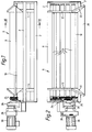
- Fig. 1 is a side view of a container included in a peeling machine for batchwise peeling according to the invention.
- Fig. 2 is a plan view of the container shown in Fig. 1.
- Fig. 3 is a schematic section of the container according to Figs. 1 and 2 on line III-III of Fig. 1.
- Figs. 4a and 4b are schematic sections of a peeling machine comprising two containers of the kind shown in Figs. 1 - 3 in operative position and discharging position, respectively.
- Fig. 5 is a plan view of three peeling rollers of a peeling machine according to the invention.
- the peeling machine according to the invention is adapted for peeling vegetable products, preferably potatoes.
- the peeling machine is of the type for batchwise peeling, i.e. the peeling machine is supplied with a certain amount of unpeeled products, whereupon the peeling operation is conducted and the peeled product is removed from the peeling machine after which a new batch of unpeeled products is supplied to the peeling machine and so on.
- the peeling machine comprises two or more containers provided with peeling means and intended for successive use, the peeling machine being adapted for transferring the vegetable products from one container to a following container in a director transversely of the longitudinal direction of the peeling rollers.
- Each of the containers constituting the peeling machine according to the invention is built on a frame consisting of longitudinal beams 2, posts 4, and conventional structural members.
- the frame supports a container 6 comprising a rear wall 8, a front wall 10 and side walls 12.
- the bottom of the container 6 is constituted by six parallel rollers 14 which at their end portions are rotatably journalled in the frame outside the side wall 12 of the container 6.
- each container 6 supports a front collector plate 16 and a rear collector plate 18, the front collector plate 16 being connected with the front wall 10 and the rear collector plate 18 being connected with the rear wall 8.
- the collector plates 16 and 18 extend obliquely inwardly beneath the rollers. In the lateral direction the collector plates 16 and 18 extend somewhat outside the side walls 12.
- the collector plates 16 and 18 have the object of guiding waste material to a collector vessel or the like positioned below the container.
- the front wall 10 of the container 6 has at its upper edge a portion 20 angled in forward direction and laterally projecting portions 22 in order to facilitate the supply of potatoes to the containers 6.
- the rollers 14 are journalled in the frame of each container 6 in such a way that the bottom of the container provided by the rollers will form a concavely curved surface having its lower edge at the front wall 10 of the container and its highest edge at the rear wall 8 thereof.
- the two rollers 14 being positioned adjacent the front wall 10 are journalled on the same height while the successive rollers are journalled with an increasing high difference in relation to the previous roller so that the radius of curvature of the bottom of the containers will decrease from the front wall 10 towards the rear wall 8.
- the bottom surface formed by the rollers is of substantially vertical orientation.
- the concavely curved surface of the bottom corresponds to the shape of a fourth of an ellipse but it is of course possible to adapt the curvature in a desired way with regard to the product to be peeled and so on.
- rollers 14 At one end the rollers 14 are provided with pulleys 24 which through V-belts, a split coupling 26 and a variator 28 are driven by an electric motor 30.
- the rollers are provided with a coating consisting of cutting carborundum grits. These carborundum grits constitute the peeling means of the peeling machine and cut or grind away the peel of the potatoes when the rollers are rotated.
- the rotational direction of all rollers 14 is such that the surfaces of the rollers, which form the bottom of the container 6 move away from the front wall 10 towards the rear wall 8.
- a suitable charge weight for potatoes is 80 - 100 kg.
- the rotational speed of the peeling rollers 14 is increased by means of the variator 28 to a suitable value, the potatoes being thereby subjected to the influence of the carborundum grits of the peeling rollers 14 which provides that the peel of the potatoes are cut or ground away at the same time as the potatoes circulate from the front wall 10 of the container up to the highest roller at the rear wall 8 from which the potatoes are thrown back to the front wall 10 of the container.
- the peel remainders fall down to the bottom of the containers below the rollers 14 and are directed to some kind of suitable collecting vessel or other collecting place by means of the collector plates 16 and 18.
- the peeled potatoes are discharged from the container 6 to a following container.
- This can be provided by tipping the container 6 which can be provided in respect of an axis, not shown, extending parallel to the rollers 14 in the vicinity of the upper edge of the rear wall 8.
- the discharging can be accomplished by providing the front wall 10 of the container with an openable door (not shown). After the door has been opened the container can be emptied by rotating the rollers 14 in the opposite direction of rotation in relation to the direction of rotation used for the peeling.
- the machine for batchwise peeling comprises two or more containers of the kind shown in Figs. 1 - 3.
- the peeling machine can consist of two containers 32 and 34, each container being constructed in the same way as the container according to Figs. 1 - 3.
- the peeling operation is hereby divided into two phases, in which the first phase which can consist of a coarse peeling without water is conducted in the container 32. After the first phase has been completed the potatoes are tipped over to the container 34 as shown in Fig. 4b, whereupon the final peeling which is constituted by a fine peeling and can be conducted with the addition of water is conducted in the container 34. It is realized that the peeling device according to Figs.
- the peeling machine can be constructed so as to include a desired number of containers so that the peeling operation can be conducted in the most suitable way.
- Fig. 5 there is shown a plan view of three peeling rollers 36, 38 and 40 in a modified embodiment of a peeling device according to the invention.
- Conventional peeling rollers can be provided by helically winding the smooth cylinder surface of the rollers by means of a strip coated with carborundum, which is bound to the surface of the roller by means of a two component binding agent.
- the strip is wound with the edges close to each other so that the roller obtains the appearance of the roller 38 in Fig. 5.
- the carborundum strip is designated with reference numeral 42 while the edges of the strip engaging each other are designated with reference numeral 44.
- the carborundum coating of the peeling rollers are positioned within surface portions separated from each other and between which smooth and preferably glossy surface portions of the rollers are provided.
- the carborundum strip 42 is wound in opposite directions on the rollers 36 and 40 so that the surface portions 46 will form on the rollers a right helix and a left helix, respectively.
- the smooth surface portions 46 between the carborundum coating contribute to the action of subjecting the potatoes to movements during the peeling operation contributing to the efficiency and uniformity of the peeling.
- the smooth surface portions 46 also contribute to the efficient removal of the peel remainders from the rollers.
- a peeling machine according to the invention can in a desired way be constructed of two or more containers of the kind shown in Figs. 1 - 3 and can be provided with different types of peeling rollers according to the principles shown in Fig. 5.
Landscapes
- Life Sciences & Earth Sciences (AREA)
- Chemical & Material Sciences (AREA)
- Engineering & Computer Science (AREA)
- Food Science & Technology (AREA)
- Polymers & Plastics (AREA)
- Apparatuses For Bulk Treatment Of Fruits And Vegetables And Apparatuses For Preparing Feeds (AREA)
- Harvesting Machines For Specific Crops (AREA)
- Pretreatment Of Seeds And Plants (AREA)
- Cultivation Of Plants (AREA)
Abstract
Description
Claims (13)
- A peeling machine for batchwise peeling of vegetable products, comprising a container (6) for receiving the vegetable products and peeling means arranged in the container (6) for removing the peel of the vegetable products during relative movement and engagement between the vegetable products and the peeling means, wherein the bottom of the container is at least in part constituted by a number of rotatable peeling rollers (14) positioned in parallel with each other, characterized in that the peeling machine comprises two or more containers provided with peeling means and intended for successive use and that the peeling machine is adapted for transfering the vegetable products from one container to a following container in a direction transversely of the longitudinal direction of the peeling rollers.
- A peeling machine according to claim 1, characterized in that the first container is adapted for coarse peeling while the following container or containers is or are intended for successively finer peeling of the vegetable products.
- A peeling machine according to claim 1 or 2, characterized in that the last container in the succession of containers is adapted for fine peeling with water and/or knife peeling.
- A peeling machine according to any of the preceding claims, characterized in that the containers are dischargeable by tipping.
- A peeling machine according to any of the preceding claims, characterized in that the peeling rollers are adapted to be rotated in the same direction during the peeling operation so that the peripheries of the rollers at the surface forming the bottom of the container move from a first side of a container towards the opposite side of the container.
- A peeling machine according to claim 5, characterized in that the peeling rollers are adapted to contribute to discharging of the containers by being rotated in an opposite rotational direction from the rotational direction during the peeling operation and that the container is provided with a discharge door at the first side of the container.
- A peeling machine according to any of the preceding claims, characterized in that at least a section of the part of the bottom of the container (6) constituted by the peeling rollers (14) forms a concavely curved surface.
- A peeling machine according to claim 7, characterized in that the peeling rollers (14) are adjacent one side (10) of the container (6) positioned in a horizontal plane and from this plane take a successively higher position in the concavely curved surface in the direction towards the opposite side (8) of the container.
- A peeling machine according to claim 7 or 8, characterized in that the curved surface is of elliptic shape.
- A peeling machine according to claim 9, characterized in that the curved surface comprises about a fourth of an ellipse having the largest radius of curvature positioned adjacent one side of the container with substantially horizontal orientation and the smallest radius of curvature positioned at the opposite side of the container with substantially vertical orientation.
- A peeling machine according to any of the preceding claims, characterized in that the peeling rollers (14) have on their surfaces cutting elements, for example consisting of cutting grits of for example carborundum, arranged as a coating on the rollers.
- A peeling machine according to claim 11, characterized in that the cutting elements on one or more of the rollers are arranged within surface portions (42) which are separated from each other and between which smooth and preferably glossy surface portions (44) of the rollers are arranged.
- A peeling machine according to claim 11, characterized in that the cutting elements on one or more of the rollers are arranged within a surface portion which as a strip extends helically around the rollers with a distance between the edges of the strip and that the space between the edges of the strip forms a helically extending, smooth and preferably gloosy surface portion.
Applications Claiming Priority (2)
| Application Number | Priority Date | Filing Date | Title |
|---|---|---|---|
| SE9202245 | 1992-07-24 | ||
| SE9202245A SE510585C2 (en) | 1992-07-24 | 1992-07-24 | Peeler for root vegetables |
Publications (2)
| Publication Number | Publication Date |
|---|---|
| EP0583569A1 EP0583569A1 (en) | 1994-02-23 |
| EP0583569B1 true EP0583569B1 (en) | 1998-12-16 |
Family
ID=20386847
Family Applications (1)
| Application Number | Title | Priority Date | Filing Date |
|---|---|---|---|
| EP93109430A Expired - Lifetime EP0583569B1 (en) | 1992-07-24 | 1993-06-12 | A peeling machine for vegetable products |
Country Status (5)
| Country | Link |
|---|---|
| US (1) | US5351610A (en) |
| EP (1) | EP0583569B1 (en) |
| AT (1) | ATE174477T1 (en) |
| DE (1) | DE69322557T2 (en) |
| SE (1) | SE510585C2 (en) |
Families Citing this family (12)
| Publication number | Priority date | Publication date | Assignee | Title |
|---|---|---|---|---|
| FI100633B (en) * | 1994-05-05 | 1998-01-30 | Elmer Egil Norrvik | Peeler for potatoes and similar products |
| SE507397C2 (en) * | 1994-11-29 | 1998-05-25 | Limas Ab | Knife peeler for root vegetables |
| US5454303A (en) * | 1994-12-27 | 1995-10-03 | Spry; Robert H. | Sheller for seed corn |
| US5544575A (en) * | 1994-12-27 | 1996-08-13 | Spry; Robert H. | Sheller for seed corn |
| US5780088A (en) * | 1997-01-17 | 1998-07-14 | David R. Zittel | Electric motor driven abrasive roller peeler and cleaning machine |
| US5786014A (en) * | 1997-04-11 | 1998-07-28 | Fmc Corporation | Capacity caustic peeler system |
| US6082252A (en) * | 1999-06-29 | 2000-07-04 | Fmc Corporation | Pre-heat apparatus for peeling system |
| FI112435B (en) | 2000-02-09 | 2003-12-15 | Formit Foodproc Ab Oy | Scaling elements |
| CA2542588A1 (en) * | 2003-10-14 | 2005-04-28 | Lyco Manufacturing, Inc. | High speed food product peeling or cleaning machine and method |
| US20050204937A1 (en) * | 2004-03-18 | 2005-09-22 | Baird Thomas D | Apparatus for peeling and scrubbing produce |
| US7143687B2 (en) * | 2004-04-29 | 2006-12-05 | Creative Serving Incorporated | Roller grill having rollers with a roughened surface |
| EP4049545A1 (en) * | 2021-02-25 | 2022-08-31 | Forsfood Group Oy | Peeling roll element pair, processing device and method for peeling vegetables |
Family Cites Families (18)
| Publication number | Priority date | Publication date | Assignee | Title |
|---|---|---|---|---|
| US1995693A (en) * | 1932-07-29 | 1935-03-26 | William E Urschel | Vegetable peeler |
| US2249787A (en) * | 1939-09-14 | 1941-07-22 | Sanitary Food Proc Company Inc | Vegetable and fruit skin removing device |
| FR1120918A (en) * | 1955-03-17 | 1956-07-17 | Alexanderwerk Ag | Potato peeling machine |
| FR1120919A (en) * | 1955-03-17 | 1956-07-17 | Alexanderwerk Ag | Potato peeler and others |
| US3566942A (en) * | 1968-08-02 | 1971-03-02 | Geneieve I Hanscom | Apparatus for peeling vegetables or fruits |
| BE790252A (en) * | 1971-10-27 | 1973-02-15 | Wallace Joseph E | APPARATUS FOR ABRASIVE Peeling VARIOUS PRODUCTS SUCH AS FRUITS OR VEGETABLES |
| US3854395A (en) * | 1973-02-12 | 1974-12-17 | Fmc Corp | Flexible cable dry peeler |
| US3946658A (en) * | 1973-12-26 | 1976-03-30 | Genevieve I. Hanscom (Formerly Genevieve I. Magnuson) | Peeling apparatus for fruit and vegetable articles |
| US4132162A (en) * | 1977-12-19 | 1979-01-02 | Magnuson Engineers, Inc. | Apparatus for peeling fruits and vegetables |
| US4237782A (en) * | 1978-11-27 | 1980-12-09 | Starr, Incorporated | Vegetable processing machine with product mobilizer apparatus |
| GB2095538A (en) * | 1981-03-27 | 1982-10-06 | Brinkman Robertus Hermanus Nic | Method and apparatus for peeling vegetables such as potatoes |
| SE431283B (en) * | 1982-07-26 | 1984-01-30 | Livsmedelsmaskiner Limas Bo Jo | Mechanical peeler for root vegetables and other products |
| US4519305A (en) * | 1984-02-03 | 1985-05-28 | Hawkeye Food Machinery, Inc. | Vegetable peeler |
| IT1215320B (en) * | 1985-11-26 | 1990-01-31 | Dassi Gianluca | ELECTRIC POTATO PEELER WITH RAKIANT THREADED ROLLERS, ROTATING WITH MUTUAL CONTRARY MOTORCYCLE. |
| US4827836A (en) * | 1987-10-20 | 1989-05-09 | Filper Industries, Inc. | Fruit and vegetable peeler |
| DE3934173A1 (en) * | 1989-10-13 | 1991-04-18 | Dornow Karl Dietrich | ROLLING OR ROLLING BOWL MACHINE FOR MECHANICAL PELLING OF EARTH OR TREE FRUIT |
| DE9013391U1 (en) * | 1990-09-21 | 1990-11-29 | Harbers, Wilhelm, 7260 Calw | Peeling machine for tubers, primarily potatoes, with quick-change roller system |
| US5106641A (en) * | 1991-04-23 | 1992-04-21 | Bichel Ronald A | Apparatus and method for waterless rotary cleaning and peeling food products and the like |
-
1992
- 1992-07-24 SE SE9202245A patent/SE510585C2/en not_active IP Right Cessation
-
1993
- 1993-06-12 DE DE69322557T patent/DE69322557T2/en not_active Expired - Lifetime
- 1993-06-12 EP EP93109430A patent/EP0583569B1/en not_active Expired - Lifetime
- 1993-06-12 AT AT93109430T patent/ATE174477T1/en active
- 1993-06-18 US US08/079,011 patent/US5351610A/en not_active Expired - Lifetime
Also Published As
| Publication number | Publication date |
|---|---|
| SE510585C2 (en) | 1999-06-07 |
| DE69322557T2 (en) | 1999-05-20 |
| US5351610A (en) | 1994-10-04 |
| SE9202245L (en) | 1994-01-25 |
| DE69322557D1 (en) | 1999-01-28 |
| ATE174477T1 (en) | 1999-01-15 |
| EP0583569A1 (en) | 1994-02-23 |
| SE9202245D0 (en) | 1992-07-24 |
Similar Documents
| Publication | Publication Date | Title |
|---|---|---|
| US5351610A (en) | Peeling machine for vegetable products | |
| US5370234A (en) | Rotary materials separator and method of separating materials | |
| US4550465A (en) | Apparatus for collecting litter and objects from a ground surface | |
| US3757946A (en) | Trash separating apparatus | |
| EP0549092A1 (en) | Rotary drum filter | |
| JPH10512796A (en) | Manual waste separation equipment | |
| FR2473795A1 (en) | METHOD, MACHINE AND INSTALLATION FOR RECOVERING THE CONSTITUENT MATERIALS OF BATTERIES OF USEFUL BATTERIES, IN PARTICULAR LEAD | |
| JPH04503631A (en) | Sorting and processing machines for goods, especially household waste | |
| AU738928B2 (en) | Fruit feeder for squeezer machines | |
| US5843508A (en) | Potato peeling system | |
| US2190970A (en) | Article loading device | |
| US2068146A (en) | Seed sorting machine | |
| JPH01197231A (en) | Carry-in/carry-out device for material to silo | |
| JP2004255257A (en) | Storing bag separation apparatus for bottle, can, and other trashes | |
| US4254874A (en) | Device for collecting and processing tree stumps | |
| US3259241A (en) | Unsnipped bean remover | |
| RU2201815C2 (en) | Method of preparation of solid domestic wastes for re-use and device for realization of this method | |
| EP1491450A1 (en) | Separation device | |
| RU2041701C1 (en) | Device for shredding of food-stuffs | |
| EP0133593B1 (en) | Scraping/peeling device | |
| CA2246271C (en) | Potato peeling apparatus | |
| JP3500546B2 (en) | Tea leaf feeding device | |
| JPH052076Y2 (en) | ||
| CN221661598U (en) | Household garbage classification treatment equipment | |
| DE3425955A1 (en) | Apparatus for the centrifugal drying of small vegetables and lettuces |
Legal Events
| Date | Code | Title | Description |
|---|---|---|---|
| PUAI | Public reference made under article 153(3) epc to a published international application that has entered the european phase |
Free format text: ORIGINAL CODE: 0009012 |
|
| AK | Designated contracting states |
Kind code of ref document: A1 Designated state(s): AT BE CH DE DK ES FR GB GR IE IT LI NL PT SE |
|
| 17P | Request for examination filed |
Effective date: 19940819 |
|
| RBV | Designated contracting states (corrected) |
Designated state(s): AT BE CH DE DK ES FR GB IT LI NL |
|
| 17Q | First examination report despatched |
Effective date: 19971117 |
|
| GRAG | Despatch of communication of intention to grant |
Free format text: ORIGINAL CODE: EPIDOS AGRA |
|
| GRAG | Despatch of communication of intention to grant |
Free format text: ORIGINAL CODE: EPIDOS AGRA |
|
| GRAH | Despatch of communication of intention to grant a patent |
Free format text: ORIGINAL CODE: EPIDOS IGRA |
|
| GRAH | Despatch of communication of intention to grant a patent |
Free format text: ORIGINAL CODE: EPIDOS IGRA |
|
| GRAA | (expected) grant |
Free format text: ORIGINAL CODE: 0009210 |
|
| AK | Designated contracting states |
Kind code of ref document: B1 Designated state(s): AT BE CH DE DK ES FR GB IT LI NL |
|
| PG25 | Lapsed in a contracting state [announced via postgrant information from national office to epo] |
Ref country code: LI Free format text: LAPSE BECAUSE OF FAILURE TO SUBMIT A TRANSLATION OF THE DESCRIPTION OR TO PAY THE FEE WITHIN THE PRESCRIBED TIME-LIMIT Effective date: 19981216 Ref country code: IT Free format text: LAPSE BECAUSE OF FAILURE TO SUBMIT A TRANSLATION OF THE DESCRIPTION OR TO PAY THE FEE WITHIN THE PRESCRIBED TIME-LIMIT;WARNING: LAPSES OF ITALIAN PATENTS WITH EFFECTIVE DATE BEFORE 2007 MAY HAVE OCCURRED AT ANY TIME BEFORE 2007. THE CORRECT EFFECTIVE DATE MAY BE DIFFERENT FROM THE ONE RECORDED. Effective date: 19981216 Ref country code: FR Free format text: LAPSE BECAUSE OF FAILURE TO SUBMIT A TRANSLATION OF THE DESCRIPTION OR TO PAY THE FEE WITHIN THE PRESCRIBED TIME-LIMIT Effective date: 19981216 Ref country code: ES Free format text: THE PATENT HAS BEEN ANNULLED BY A DECISION OF A NATIONAL AUTHORITY Effective date: 19981216 Ref country code: CH Free format text: LAPSE BECAUSE OF FAILURE TO SUBMIT A TRANSLATION OF THE DESCRIPTION OR TO PAY THE FEE WITHIN THE PRESCRIBED TIME-LIMIT Effective date: 19981216 Ref country code: BE Free format text: LAPSE BECAUSE OF FAILURE TO SUBMIT A TRANSLATION OF THE DESCRIPTION OR TO PAY THE FEE WITHIN THE PRESCRIBED TIME-LIMIT Effective date: 19981216 Ref country code: AT Free format text: LAPSE BECAUSE OF FAILURE TO SUBMIT A TRANSLATION OF THE DESCRIPTION OR TO PAY THE FEE WITHIN THE PRESCRIBED TIME-LIMIT Effective date: 19981216 |
|
| REF | Corresponds to: |
Ref document number: 174477 Country of ref document: AT Date of ref document: 19990115 Kind code of ref document: T |
|
| REG | Reference to a national code |
Ref country code: CH Ref legal event code: EP |
|
| REF | Corresponds to: |
Ref document number: 69322557 Country of ref document: DE Date of ref document: 19990128 |
|
| PG25 | Lapsed in a contracting state [announced via postgrant information from national office to epo] |
Ref country code: DK Free format text: LAPSE BECAUSE OF FAILURE TO SUBMIT A TRANSLATION OF THE DESCRIPTION OR TO PAY THE FEE WITHIN THE PRESCRIBED TIME-LIMIT Effective date: 19990316 |
|
| EN | Fr: translation not filed | ||
| REG | Reference to a national code |
Ref country code: CH Ref legal event code: PL |
|
| PLBE | No opposition filed within time limit |
Free format text: ORIGINAL CODE: 0009261 |
|
| STAA | Information on the status of an ep patent application or granted ep patent |
Free format text: STATUS: NO OPPOSITION FILED WITHIN TIME LIMIT |
|
| 26N | No opposition filed | ||
| REG | Reference to a national code |
Ref country code: GB Ref legal event code: IF02 |
|
| PGFP | Annual fee paid to national office [announced via postgrant information from national office to epo] |
Ref country code: GB Payment date: 20110525 Year of fee payment: 19 |
|
| PGFP | Annual fee paid to national office [announced via postgrant information from national office to epo] |
Ref country code: DE Payment date: 20120607 Year of fee payment: 20 Ref country code: NL Payment date: 20120614 Year of fee payment: 20 |
|
| GBPC | Gb: european patent ceased through non-payment of renewal fee |
Effective date: 20120612 |
|
| PG25 | Lapsed in a contracting state [announced via postgrant information from national office to epo] |
Ref country code: GB Free format text: LAPSE BECAUSE OF NON-PAYMENT OF DUE FEES Effective date: 20120612 |
|
| REG | Reference to a national code |
Ref country code: DE Ref legal event code: R071 Ref document number: 69322557 Country of ref document: DE |
|
| REG | Reference to a national code |
Ref country code: NL Ref legal event code: V4 Effective date: 20130612 |
|
| PG25 | Lapsed in a contracting state [announced via postgrant information from national office to epo] |
Ref country code: DE Free format text: LAPSE BECAUSE OF EXPIRATION OF PROTECTION Effective date: 20130613 |