EP0583166A2 - A stream selector for a process analyzer - Google Patents
A stream selector for a process analyzer Download PDFInfo
- Publication number
- EP0583166A2 EP0583166A2 EP19930306369 EP93306369A EP0583166A2 EP 0583166 A2 EP0583166 A2 EP 0583166A2 EP 19930306369 EP19930306369 EP 19930306369 EP 93306369 A EP93306369 A EP 93306369A EP 0583166 A2 EP0583166 A2 EP 0583166A2
- Authority
- EP
- European Patent Office
- Prior art keywords
- valve
- passageway
- block
- valves
- compartment
- Prior art date
- Legal status (The legal status is an assumption and is not a legal conclusion. Google has not performed a legal analysis and makes no representation as to the accuracy of the status listed.)
- Granted
Links
Images


Classifications
-
- G—PHYSICS
- G01—MEASURING; TESTING
- G01N—INVESTIGATING OR ANALYSING MATERIALS BY DETERMINING THEIR CHEMICAL OR PHYSICAL PROPERTIES
- G01N35/00—Automatic analysis not limited to methods or materials provided for in any single one of groups G01N1/00 - G01N33/00; Handling materials therefor
- G01N35/10—Devices for transferring samples or any liquids to, in, or from, the analysis apparatus, e.g. suction devices, injection devices
- G01N35/1095—Devices for transferring samples or any liquids to, in, or from, the analysis apparatus, e.g. suction devices, injection devices for supplying the samples to flow-through analysers
- G01N35/1097—Devices for transferring samples or any liquids to, in, or from, the analysis apparatus, e.g. suction devices, injection devices for supplying the samples to flow-through analysers characterised by the valves
-
- G—PHYSICS
- G01—MEASURING; TESTING
- G01N—INVESTIGATING OR ANALYSING MATERIALS BY DETERMINING THEIR CHEMICAL OR PHYSICAL PROPERTIES
- G01N1/00—Sampling; Preparing specimens for investigation
- G01N1/02—Devices for withdrawing samples
- G01N1/10—Devices for withdrawing samples in the liquid or fluent state
- G01N1/16—Devices for withdrawing samples in the liquid or fluent state with provision for intake at several levels
-
- G—PHYSICS
- G01—MEASURING; TESTING
- G01N—INVESTIGATING OR ANALYSING MATERIALS BY DETERMINING THEIR CHEMICAL OR PHYSICAL PROPERTIES
- G01N35/00—Automatic analysis not limited to methods or materials provided for in any single one of groups G01N1/00 - G01N33/00; Handling materials therefor
- G01N2035/00178—Special arrangements of analysers
- G01N2035/00326—Analysers with modular structure
-
- Y—GENERAL TAGGING OF NEW TECHNOLOGICAL DEVELOPMENTS; GENERAL TAGGING OF CROSS-SECTIONAL TECHNOLOGIES SPANNING OVER SEVERAL SECTIONS OF THE IPC; TECHNICAL SUBJECTS COVERED BY FORMER USPC CROSS-REFERENCE ART COLLECTIONS [XRACs] AND DIGESTS
- Y10—TECHNICAL SUBJECTS COVERED BY FORMER USPC
- Y10T—TECHNICAL SUBJECTS COVERED BY FORMER US CLASSIFICATION
- Y10T137/00—Fluid handling
- Y10T137/6851—With casing, support, protector or static constructional installations
-
- Y—GENERAL TAGGING OF NEW TECHNOLOGICAL DEVELOPMENTS; GENERAL TAGGING OF CROSS-SECTIONAL TECHNOLOGIES SPANNING OVER SEVERAL SECTIONS OF THE IPC; TECHNICAL SUBJECTS COVERED BY FORMER USPC CROSS-REFERENCE ART COLLECTIONS [XRACs] AND DIGESTS
- Y10—TECHNICAL SUBJECTS COVERED BY FORMER USPC
- Y10T—TECHNICAL SUBJECTS COVERED BY FORMER US CLASSIFICATION
- Y10T137/00—Fluid handling
- Y10T137/8593—Systems
- Y10T137/86292—System with plural openings, one a gas vent or access opening
-
- Y—GENERAL TAGGING OF NEW TECHNOLOGICAL DEVELOPMENTS; GENERAL TAGGING OF CROSS-SECTIONAL TECHNOLOGIES SPANNING OVER SEVERAL SECTIONS OF THE IPC; TECHNICAL SUBJECTS COVERED BY FORMER USPC CROSS-REFERENCE ART COLLECTIONS [XRACs] AND DIGESTS
- Y10—TECHNICAL SUBJECTS COVERED BY FORMER USPC
- Y10T—TECHNICAL SUBJECTS COVERED BY FORMER US CLASSIFICATION
- Y10T137/00—Fluid handling
- Y10T137/8593—Systems
- Y10T137/877—With flow control means for branched passages
- Y10T137/87829—Biased valve
- Y10T137/87837—Spring bias
- Y10T137/87861—Spring coaxial with valve
-
- Y—GENERAL TAGGING OF NEW TECHNOLOGICAL DEVELOPMENTS; GENERAL TAGGING OF CROSS-SECTIONAL TECHNOLOGIES SPANNING OVER SEVERAL SECTIONS OF THE IPC; TECHNICAL SUBJECTS COVERED BY FORMER USPC CROSS-REFERENCE ART COLLECTIONS [XRACs] AND DIGESTS
- Y10—TECHNICAL SUBJECTS COVERED BY FORMER USPC
- Y10T—TECHNICAL SUBJECTS COVERED BY FORMER US CLASSIFICATION
- Y10T137/00—Fluid handling
- Y10T137/8593—Systems
- Y10T137/877—With flow control means for branched passages
- Y10T137/87885—Sectional block structure
-
- Y—GENERAL TAGGING OF NEW TECHNOLOGICAL DEVELOPMENTS; GENERAL TAGGING OF CROSS-SECTIONAL TECHNOLOGIES SPANNING OVER SEVERAL SECTIONS OF THE IPC; TECHNICAL SUBJECTS COVERED BY FORMER USPC CROSS-REFERENCE ART COLLECTIONS [XRACs] AND DIGESTS
- Y10—TECHNICAL SUBJECTS COVERED BY FORMER USPC
- Y10T—TECHNICAL SUBJECTS COVERED BY FORMER US CLASSIFICATION
- Y10T137/00—Fluid handling
- Y10T137/8593—Systems
- Y10T137/877—With flow control means for branched passages
- Y10T137/87893—With fluid actuator
-
- Y—GENERAL TAGGING OF NEW TECHNOLOGICAL DEVELOPMENTS; GENERAL TAGGING OF CROSS-SECTIONAL TECHNOLOGIES SPANNING OVER SEVERAL SECTIONS OF THE IPC; TECHNICAL SUBJECTS COVERED BY FORMER USPC CROSS-REFERENCE ART COLLECTIONS [XRACs] AND DIGESTS
- Y10—TECHNICAL SUBJECTS COVERED BY FORMER USPC
- Y10T—TECHNICAL SUBJECTS COVERED BY FORMER US CLASSIFICATION
- Y10T137/00—Fluid handling
- Y10T137/8593—Systems
- Y10T137/87917—Flow path with serial valves and/or closures
- Y10T137/87981—Common actuator
Definitions
- the present invention relates to stream selection. More particularly, the present invention relates to the selection of sample streams being routed to a process analyzer.
- sample streams are generally transported near to an analyzer by tubing or piping.
- An automated valving manifold usually electronically controlled, sequentially selects and diverts individual sample streams to the automated analyzer. This type of valving arrangement is generally referred to as a "stream-select manifold.”
- sample-stream cross-contamination does not occur; i.e., absence of contamination of one sample stream by another in the sample stream selected for analysis.
- the most likely source of cross-contamination is from leaking "stream-select valves" in the stream-selection valving manifold.
- Valve-manifold designs have either "dead volume,” irregular passageways, or large internal volumes, which require longer period of sample flow (purging) before all residual fluid from a previously selected sample stream is removed.
- a common source of "difficult-to-purge" internal valve manifold volume is pipe fittings which provide an irregular internal surface.
- a common source of dead volume is the space between the block valve of a "non-selected" stream and the common sample fluid passage to an analyzer.
- Valves utilized in stream-select manifolds for the most part were designed for ordinary pneumatic and hydraulic fluid-handling applications. Designs have been altered to some degree to accommodate stream-select manifold requirements. But few are designed exclusively for that purpose. Those which are designed primarily for stream selection are of the single block valve design, and are therefore prone to cross-contamination problems when even a slight leak develops.
- Modular valve manifold arrangements are well known and in common service. These manifolds, however, are designed to facilitate the addition or removal of individual valves, and to reduce the number of tube and/or pipe fittings required. Their main purpose is to reduce space in pneumatic and hydraulic, not analytical, applications. Hence little consideration has been given to reducing internal volume and/or "dead” (unpurged) space, or the prevention of cross-contamination by residual fluids. Few if any provide double-block-and-bleed (DBB) protection from cross-contamination.
- DBB double-block-and-bleed
- bellows/diaphragm valve stem seals are very effective during their normal service life, but have a severe and potentially unsafe failure mode.
- Pneumatic actuation is often preferred in lieu of electric actuation for valves used in hazardous or electrically-classified environments.
- Current valve designs generally employ discrete pneumatic actuators usually mounted external to the valve with mechanical linkage through a seal to the internal valving mechanism. This arrangement results in a bulky design which takes up large amounts of valuable panel space. This is a particularly important consideration when considering the cost of providing panel space in a typical analyzer housing or environment. The large bulk also precludes close coupling of valves to minimize internal valve-manifold volume.
- the present invention in one aspect provides a valve module for a process analyzer.
- the module comprises a first block valve having a first opening, a second block valve having a second opening, and a bleed valve having a third opening.
- the first and second block valves are so constructed and arranged that both are closed simultaneously or both are open simultaneously.
- the block valves and the bleed valve are so constructed and arranged that, in a first mode, the block valves are closed and the bleed valve is open; in a second mode the block valves are open and the bleed valve is closed; and in a third mode, all of the valves are open, thereby ensuring that the module is completely purged.
- the valve module further comprises flat-face sealing means for closing the valves by pressing the sealing means against a flat sealing surface, and for opening the valves by breaking contact between the sealing means and the flat sealing surface.
- the present invention provides a stream-selection valve manifold.
- the valve manifold comprises first and second valve modules joined side by side to form a common outlet passageway and a common vent passageway.
- Each valve module includes two block valves and a bleed valve.
- the block valves are so constructed and arranged that both are closed simultaneously or both are open simultaneously.
- the three valves are so constructed and arranged that, in a first mode, the block valves are closed and the bleed valve is open; in a second mode, the block valves are open and the bleed valve is closed; and in a third mode, all three valves are open, thereby ensuring that the module is completely purged.
- Each valve module further comprises flat-face sealing means for closing the valves by pressing the sealing means against a flat sealing surface, and for opening the valves by breaking contact between the sealing means and the flat sealing surface.
- One of the block valves communicates with an inlet passageway.
- the other block valve communicates with an outlet passageway.
- the bleed valve communicates with a vent passageway.
- Flow-through means hold the first and second valve modules in a fixed configuration wherein the outlet passageways of the first and second valve modules are aligned to form a common outlet passageway to and through the flow-through holding means, and the vent passageways from the first and second valve modules are aligned to form a common vent passageway, thereby ensuring that the manifold is completely purged.
- the invention provides a single block-and-bleed valve module.
- the module comprises a block valve, a sample-fluid compartment, a vent compartment, an internal pneumatic actuator, a sample-inlet first passageway, a sample-outlet second passageway, third and fourth passageways, first biasing means for closing the block valve, second biasing means for opening the valve, and a body having a cavity therein for housing the block valve, the sample-fluid compartment, the vent compartment, the pneumatic actuator, and the first, second, third, and fourth passageways.
- the internal pneumatic actuator includes an actuator piston and an actuator compartment.
- the actuator compartment is constructed and arranged to receive compressed gas from an external source.
- the first biasing means close the block valve by urging the piston in a first direction.
- the second biasing means which include a compressed gas, open the valve by urging the piston in a second direction.
- the block valve is so constructed and arranged that, when closed, fluid communication is blocked between the inlet passageway and the sample-fluid compartment; when open, the inlet passageway, the sample-fluid compartment, and the outlet passageway are in fluid communication.
- the inlet passageway provides means for fluid communication from the external environment to the sample-fluid compartment.
- the outlet passageway provides means for fluid communication from the sample-fluid compartment to the external environment.
- the third passageway provides means for introducing a compressed gas into the actuator compartment.
- the fourth passageway provides means for fluid communication between the vent compartment and an external area suitable for the safe disposal of fluids contained within the valve module.
- the pressure within the vent compartment and the fourth passageway is normally maintained at a level equal to or lower than that of the sample-fluid compartment, the sample-inlet passageway, the sample-outlet passageway, and the actuator compartment, in order to prevent fugitive emission of the sample fluid or of the compressed gas from the module into unprotected areas of the external environment.
- Compressed fluid compressed gas or liquid
- Figure 1 is a schematic representation of a second embodiment of a stream-selection valve manifold for a process analyzer, made in accordance with the principles of the present invention.
- FIG. 2 is a schematic representation of a shutoff and atmospheric reference vent for a process gas chromatograph, made in accordance with the principles of the present invention.
- Figure 3 is a schematic representation of a first embodiment of a stream-selection valve manifold for a process analyzer, made in accordance with the principles of the present invention.
- Figure 4 is an isometric view of the stream-selection valve manifold shown schematically in Figure 3.
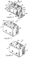
- Figure 5 is an isometric view of the shutoff and atmospheric reference vent shown in Figure 2.
- Figure 6 is an isometric view of the second embodiment of a stream-selection valve manifold for a process analyzer shown schematically in Figure 1.
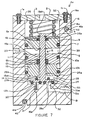
- Figure 7 is a cross-sectional view of the valve manifold shown in Figure 4, taken along the cutting line 7-7.
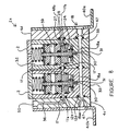
- Figure 8 is a cross-sectional view of the valve manifold shown in Figure 4, taken along the cutting line 8-8.
- Figures 9 and 10 are portions of the cross-sectional view of the valve manifold shown in Figure 7.
- FIG 11 is a schematic representation showing the removal of a valve module from the stream-selection valve manifold shown in Figures 3 and 4.
- Figure 12 is a cross-sectional view of the manifold shown in Figure 4, taken along the cutting line 12-12.
- Figure 13 is a vertical cross-sectional view of a single block-and-bleed valve module, made in accordance with the principles of the present invention.
- the present invention in a first embodiment ( Figure 3), provides a valve module 33 for a process analyzer.
- the module 33 comprises an internal pneumatic actuator, an inlet block valve 33b, an outlet block valve 33c, and a bleed valve 33d.
- the two block valves 33b, 33c are constructed and arranged so that both are closed or both are open simultaneously.
- the bleed valve 33d is constructed and arranged so that when the block valves 33b, 33c are open, the bleed valve 33d is closed; when the block valves 33b, 33c are closed, the bleed valve 33d is open.
- the three valves 33b, 33c, 33d are contained and disposed in and by a body 16 having an inlet port 19, an outlet port 18a, and a vent port 17 for the inlet valve 33b, outlet valve 33c, and bleed valve 33d, respectively ( Figures 7 - 10).
- the internal pneumatic actuator comprises a valve poppet 15 having a stem 15a and a flange 15b, first biasing means 3 to urge the poppet 15 downward, and second biasing means to force the poppet 15 upward ( Figures 7, 9, and 10).
- the first biasing means 3 may be a spring 3, a compressed gas, or other means.
- the first biasing means is a spring 3 housed in a chamber 32.
- the second biasing means is preferably a compressed gas; it is stronger than the first biasing means 3, and prevails when the two are in opposition.
- the portion of the cavity 26 providing the second biasing means may be maintained at a pressure substantially above atmospheric, even "in the absence of the second biasing means.” Such a condition may indeed be beneficial, in order to prevent fugitive fluid emission from the modular body 16. It is only necessary, as stated above, that the second biasing means be understood and is herein defined as being sufficient to overcome the first biasing means.
- valves 33b, 33c, and 33d comprise flat-face sealing means. Even more preferably, the valves 33b, 33c, and 33d include O-rings ( Figures 7, 9, and 10).
- a seal-plug bottom part 13 is positioned on a shoulder 26a formed by a reduction of cross-sectional area at the lower end 26b of the cavity 26.
- An O-ring 10b seals the outer surface of the seal-plug bottom part 13 to the inner surface of the cavity 26.
- a seal-plug top part 11 is disposed over the seal-plug bottom part 13.
- An O-ring 10a seals the outer surface of the seal-plug top part 11 to the inner surface of the cavity 26.
- a snap ring 8 retains the seal-plug top part 11 and seal-plug bottom part 13 in a fixed position.
- the poppet 15, comprising a stem 15a and flange 15b, extends axially within the cavity 26.
- Grooves 29a and 29b in the lower surface of the poppet 15 retain O-rings 12a and 12b.
- An alignment pin 31 disposed in a passageway 30 maintains axial alignment of the O-ring 12a with a passageway 32 and of O-ring 12b with the passageway 30.
- a portion 12aa of the O-ring 12a which extends beyond its retaining groove 29a, when forced against the lower surface of a first compartment 24 and in axial alignment with the passageway 32, forms the sample inlet valve 33b which either blocks or permits fluid communication between a sample inlet passageway 19, the passageway 32, and the first compartment 24.
- the O-ring 12b forms the sample outlet valve 33c which blocks or permits fluid communication between the outlet passageway 18a, the passageway 30, and the first compartment 24.
- An O-ring 14 axially disposed around the lower end 15aa of the poppet stem 15a, the upper surface of the poppet flange 15b, and the lower surface of the seal-plug bottom part 13 forms the bleed valve 33d which blocks or permits fluid communication between the first compartment 24 and passageways 28, 27, and 17. ( Figures 7, 8, and 12.)
- the width of the grooves 29a and 29b is from about seventy-five to about ninety-five percent of the width of the O-rings 12a and 12b, respectively.
- the width of the grooves 29a and 29b is from about eighty to about ninety percent of the width of the O-rings 12a and 12b, respectively.
- the O-rings 12a and 12b are made of an elastomer having a hardness of from about sixty-five to about seventy-five durometer units, as measured on a Shore "A" gauge, and the depth of the grooves 29a and 29b is from about eighty-seven to about ninety-one percent of the width of the O-rings 12 and 12b, respectively.
- valve poppet 15 is normally maintained in the extreme lower position ( Figure 7) by the downward force of the compression return spring 3 applied to the poppet stem 15a via an actuator washer 5, actuator piston 9, and an E-ring 4b.
- a second compartment 39 comprises the middle portion of the cavity 26.
- the second compartment 39 is formed by the upper flat surface of the seal-plug top part 11 and the lower flat surface of the piston 9.
- an external pneumatic source not shown
- an upward force resulting from the pneumatic pressure applied to the lower surface of the piston 9 overcomes the downward force applied by the compression return spring 3, and lifts the poppet 15 to its extreme upper position ( Figure 9).
- the poppet 15 is in the intermediate position shown in Figure 10 for only a very short period of time while in transit between the two extreme positions.
- O-rings 6b and 12c provide a dynamic seal between the plug-seal top part 11 and the poppet stem 15a, thereby ensuring fluid isolation at any position of the stem 15a between the passageway 28 and the second compartment 39.
- the piston 9 and washer 5 are axially disposed and retained on the upper portion 15ab of the poppet 15 by E-rings 4a and 4b.
- the O-ring 6a retained by the washer 5 and axially disposed in a third compartment 26a formed by the upper surface of the piston 9 and the lower surface of the washer 5, provides fluid isolation between the second compartment 39 and a fourth compartment 32, in which the spring 3 is disposed, and which is referenced to (equilibrated with) the atmosphere.
- the fourth compartment 32 is formed by the lower surface of a cover 2 and the upper surface of the washer 5.
- An O-ring 7 provides a dynamic seal between the piston 9 and the inside wall of the cavity 26.
- the cover 2 held to the top 16a of the body 16 by screws 1a and 1b, retains compression spring 3 ( Figure 7).
- the present invention provides a stream-selection valve manifold 2a for a process analyzer.
- the manifold 2a comprises: (a) a plurality of pneumatic valve modules 33 joined side-by-side, (b) first and second end plates 4c and 4d, and (c) first and second mounting brackets 40a and 40b.
- the passageway 18a in each valve module 33 is in alignment with the passageways 18a of adjacent valve modules 33 in the manifold 2a.
- the first and second end plates 4c and 4d which are in fluid communication with the passageways 18a of adjacent modules 33, provide means for external fluid communication to a single common passageway 18 formed by the outlet passageways 18a of the individual modules 33.
- An O-ring 12d ( Figure 8) in a gland 18aa at the end of each module's passageway 18a provides a fluid seal with the passageway 18a of adjacent modules 33 and/or the end plates 4c, 4d.
- the passageways 17 in the valve modules 33 are joined and sealed with an O-ring 12e in a gland 17a to form a common vent passageway 36 which terminates as a threaded opening 50 in the end plate 4c.
- the passageway 17 is closed at the end plate 4d by an O-ring 17b in a gland 48b ( Figures 3 and 8).
- a valve module 33 can be removed by rotating it along a path 100 from a first point 100a to to a second point 100b about the first threaded rod 41a disposed in a first slot 45.
- Figure 11. After the valve module 33 has been rotated sufficiently (100b) to clear a second slot 42 from a second threaded rod 41a disposed in a second slot 42, the module 33 can be removed from the manifold 2a.
- Figures 4 and 11. When a module 33 is thus removed, the remaining modules 33 and the end plates 4c, 4d remain assembled.
- the construction of the manifold 2a permits rapid replacement of one or more of the valve modules 33 in the field.
- the passageways 18a of the individual valve modules form a common passageway 18 ( Figures 1 and 3) to an analyzer (not shown).
- This common passageway 18 occupies a very small volume, and is easy to purge out.
- the passageway 18 is straight and smooth, has a regular surface, and has no "dead volume” or empty space, thereby significantly reducing the time required for sample flow (purging) before all residual fluid from a previously-selected sample stream is displaced.
- the width of the passageway 18 is from about 0.06" to about 0.08".
- the volume of each passageway 18a in each valve module 33 is from about 0.06 to about 0.08 cubic centimeters; yet the passageways 18a and 18 are not restrictive of fluid flow.
- the valve module C v is 0.05.
- the passageways 18a are located in very close proximity to the outlet valves 33c.
- the passageway 30, which connects the outlet valve 33c to the passageway 18a, is preferably from about 0.045" to about 0.055" in length.
- the passageway 18a has no "dead” or unpurged space; hence it purges out cleanly and quickly when serving as a conduit for fluid communication in the manifold 2a.
- Internal passageways 36 and 47 ( Figure 8) of the end plates 4c and 4d, respectively, are also approximately 0.07" in width, and are also constructed without "dead” or unpurged space. Hence the common passageway 18 servicing the entire manifold 2a has a very small volume and no dead space.
- valve module 33 When a valve module 33 is actuated and the block valves 33b, 33c are opened, sample fluid from that module flows into the common passageway 18 and out of both end plates 4c, 4d.
- the two flow paths may either be joined external to the manifold 2a, or they may remain divided, with fluid flowing from one of the end plates to vent or bypass, and fluid flowing from the other end plate routed to an analyzer. This pattern of fluid flow ensures that the entire common passageway 18 is adequately purged, thereby significantly reducing the number of fittings as well as the labor and time required for assembling the valve manifold 2a.
- the invention provides a shutoff and atmospheric reference vent 2b for a process gas chromatograph (not shown).
- a process gas chromatograph (not shown).
- the two valve modules 33a are housed in a flow-through modular body 40.
- the invention 2c ( Figures 1 and 6) provides a stream-selection valve manifold comprising two valve modules 33 disposed side-by-side in a flow-through modular body 41, thereby eliminating the need for the end plates 4c, 4d and the mounting brackets 40a, 40b of the manifold 2a ( Figures 4 and 8).
- the present invention provides a single block-and-bleed valve module for selectively controlling fluid flow.
- the single block-and-bleed module 79 is comprised of a block valve, a sample fluid compartment 52, a vent compartment 53, and an internal pneumatic actuator, all of which are disposed within a cavity 56 in a body 51.
- the block valve is constructed and arranged so that, when closed, fluid communication is blocked between an inlet passageway 54 and the sample fluid compartment 52.
- an inlet passageway 54, the sample fluid compartment 52, and an outlet passageway 55 are in fluid communication.
- the outlet passageway 55 and the sample fluid compartment 52 are in fluid communication in both the "open" and "closed” positions of the block valve.
- a poppet 57 is axially disposed within the cavity 56.
- a groove 58 in the lower surface 61 of the poppet 57 retains a first O-ring 59 in axial alignment with the passageway 54.
- the passageway 54 provides means for fluid communication from the environment external of the body 51 to the sample-fluid compartment 52.
- the passageway 55 provides means for fluid communication from the sample-fluid compartment 52 to the environment external of the valve body 51. The function of the passageways 54 and 55 can be reversed without altering the function of the valve module 79.
- An actuator piston 63 is formed by an enlargment of the width of the poppet 57 near the longitudional center of the poppet 57.
- the poppet 57 is normally maintained in the extreme lower position shown in Figure 13 by the downward force of a compression return spring 62 applied to the actuator piston 63.
- the internal pneumatic actuator comprises the actuator piston 63 and an actuator compartment 64.
- an external source of sufficient pneumatic pressure is supplied to the actuator compartment 64 via a passageway 65, an upward force resulting from the pneumatic pressure applied to the lower surface of the actuator piston 63 overcomes the downward force applied by the compression spring 62, and lifts the poppet 57 to its extreme upper position.
- the upper surface 66 of the poppet 57 contacts cover 67 to limit the travel of the poppet 57 in its extreme upper position.
- the cover 67 is held to the top 68 of the body 51 by screws 69 and 70.
- the portion 60 of the O-ring 59 contacting the lower surface 71 of the compartment 51 limits the travel of the poppet 57 in its extreme lower position.
- the block valve is in a closed mode when the poppet 57 is at its extreme lower position, and in an open mode when the poppet is at its extreme upper position.
- the compartment 52 is formed by the annulus between the poppet 57 and the inner surface of the cavity 56, from the lower surface 71 of the cavity 56 to a second O-ring 72.
- the vent compartment 53 is formed by the annulus between the poppet 57 and the inner surface of the cavity 56, from the second O-ring 72 to a third O-ring 73.
- the actuator compartment 64 is formed by the annulus between the poppet 57 and the inner surface of the cavity 56, from the third O-ring 73 to a fourth O-ring 74.
- the return spring 62 is housed in a spring compartment 75 formed in the upper portion of the cavity 56 between the fourth O-ring 74 and the lower surface of the cover 67.
- a passageway 76 provides fluid communication between the vent compartment 53 and the environment external of the body 51.
- the end of the passageway 76 terminating at the external surface of the valve body 51 is normally in fluid communication, by tubing or piping means, with an area (not shown) suitable for the safe disposal of sample fluids contained within the sample-fluid compartment 52.
- Pressure within the passageway 76 and the compartment 53 is normally maintained at a level equal to or lower than than that of the sample-fluid compartment 52, the passageway 54, the passageway 55, and the compartment 64.
- the O-rings 72, 73, and 74 provide fluid sealing between the compartments 52, 53, 64, and 75. Should the O-ring 72 fail, resulting in sample fluid from the sample-fluid compartment 52 entering the vent compartment 53, the passageway 76 will conduct this fluid to the safe-disposal area referred to above.
- pneumatic-supply gas entering the vent compartment 53 as a result of breaching the O-ring 73, should that O-ring fail, would also be conducted to the external safe-disposal area in fluid communication with the passageway 76.
- Mounting holes 77 and 78 provide convenient means for mounting the valve module 51.
- each valve is very tolerant of scratching of and/or irregularities in the sealing means, of abrasive particulates which may be present in the sample fluid, and even of minor structural damage to the sealing means.
Abstract
Description
- The present invention relates to stream selection. More particularly, the present invention relates to the selection of sample streams being routed to a process analyzer.
- It is common practice to utilize a single automated process analyzer for analyzing multiple sample streams. This signficantly reduces the cost of analyzing gas and liquid process streams in petrochemical plants, refineries and other process-related industries. The sample streams are generally transported near to an analyzer by tubing or piping. An automated valving manifold, usually electronically controlled, sequentially selects and diverts individual sample streams to the automated analyzer. This type of valving arrangement is generally referred to as a "stream-select manifold."
- It is extremely important that sample-stream cross-contamination does not occur; i.e., absence of contamination of one sample stream by another in the sample stream selected for analysis. The most likely source of cross-contamination is from leaking "stream-select valves" in the stream-selection valving manifold.
- Another common problem is the contamination of a stream selected for analysis by residual fluid from a previous sample stream. This is likely to occur in a common passageway between the valve manifold and the analyzer. Valve-manifold designs have either "dead volume," irregular passageways, or large internal volumes, which require longer period of sample flow (purging) before all residual fluid from a previously selected sample stream is removed. A common source of "difficult-to-purge" internal valve manifold volume is pipe fittings which provide an irregular internal surface. A common source of dead volume is the space between the block valve of a "non-selected" stream and the common sample fluid passage to an analyzer.
- When longer sample-stream purge periods are required, it reduces the number of analyses which can be performed by an analyzer in a given period of time. This can increase the cost for analysis by requiring additional analyzers or otherwise negatively impact process adjustments based on current analysis.
- Most important, however, is the increased volume of purged sample material which must be discarded. This also increases cost and presents a greater risk of contaminating the environment.
- Valves utilized in stream-select manifolds for the most part were designed for ordinary pneumatic and hydraulic fluid-handling applications. Designs have been altered to some degree to accommodate stream-select manifold requirements. But few are designed exclusively for that purpose. Those which are designed primarily for stream selection are of the single block valve design, and are therefore prone to cross-contamination problems when even a slight leak develops.
- Modular valve manifold arrangements are well known and in common service. These manifolds, however, are designed to facilitate the addition or removal of individual valves, and to reduce the number of tube and/or pipe fittings required. Their main purpose is to reduce space in pneumatic and hydraulic, not analytical, applications. Hence little consideration has been given to reducing internal volume and/or "dead" (unpurged) space, or the prevention of cross-contamination by residual fluids. Few if any provide double-block-and-bleed (DBB) protection from cross-contamination. Some manifold/valve designs even allow stacking of manifold modules to create a manifold of a desired length; however, the valves are a separate entity, and are attached to the manifold.
- Another common problem with stream-selection valves is "fugitive emission" of sample fluids. This typically occurs when a valve stem seal fails. A metal bellows or diaphragm is frequently employed to seal the external actuation linkage to a valve's internal sealing mechanism. This arrangement, particularly when used in combination with a secondary packing, is very effective in reducing fugitive emission from valves. However, embrittlement of metal bellows or diaphragms, particulaly in hydrogen-rich sample-stream service, and fatigue from repeated actuation, often causes premature stem-seal failures. Additionally, valves employing the bellows/diaphragm seal design are expensive, thus limiting their application. Furthermore, when the bellows or diaphragm fails, there can be an abrupt release of potentially flammable and/or toxic fluids to the surrounding environment. In summary, bellows/diaphragm valve stem seals are very effective during their normal service life, but have a severe and potentially unsafe failure mode.
- Pneumatic actuation is often preferred in lieu of electric actuation for valves used in hazardous or electrically-classified environments. Current valve designs generally employ discrete pneumatic actuators usually mounted external to the valve with mechanical linkage through a seal to the internal valving mechanism. This arrangement results in a bulky design which takes up large amounts of valuable panel space. This is a particularly important consideration when considering the cost of providing panel space in a typical analyzer housing or environment. The large bulk also precludes close coupling of valves to minimize internal valve-manifold volume.
- In general, the present invention in one aspect provides a valve module for a process analyzer. The module comprises a first block valve having a first opening, a second block valve having a second opening, and a bleed valve having a third opening. The first and second block valves are so constructed and arranged that both are closed simultaneously or both are open simultaneously. The block valves and the bleed valve are so constructed and arranged that, in a first mode, the block valves are closed and the bleed valve is open; in a second mode the block valves are open and the bleed valve is closed; and in a third mode, all of the valves are open, thereby ensuring that the module is completely purged.
- The valve module further comprises flat-face sealing means for closing the valves by pressing the sealing means against a flat sealing surface, and for opening the valves by breaking contact between the sealing means and the flat sealing surface.
- In a second aspect the present invention provides a stream-selection valve manifold. The valve manifold comprises first and second valve modules joined side by side to form a common outlet passageway and a common vent passageway. Each valve module includes two block valves and a bleed valve. The block valves are so constructed and arranged that both are closed simultaneously or both are open simultaneously. The three valves are so constructed and arranged that, in a first mode, the block valves are closed and the bleed valve is open; in a second mode, the block valves are open and the bleed valve is closed; and in a third mode, all three valves are open, thereby ensuring that the module is completely purged.
- Each valve module further comprises flat-face sealing means for closing the valves by pressing the sealing means against a flat sealing surface, and for opening the valves by breaking contact between the sealing means and the flat sealing surface. One of the block valves communicates with an inlet passageway. The other block valve communicates with an outlet passageway. The bleed valve communicates with a vent passageway. Flow-through means hold the first and second valve modules in a fixed configuration wherein the outlet passageways of the first and second valve modules are aligned to form a common outlet passageway to and through the flow-through holding means, and the vent passageways from the first and second valve modules are aligned to form a common vent passageway, thereby ensuring that the manifold is completely purged.
- In a third aspect, the invention provides a single block-and-bleed valve module. The module comprises a block valve, a sample-fluid compartment, a vent compartment, an internal pneumatic actuator, a sample-inlet first passageway, a sample-outlet second passageway, third and fourth passageways, first biasing means for closing the block valve, second biasing means for opening the valve, and a body having a cavity therein for housing the block valve, the sample-fluid compartment, the vent compartment, the pneumatic actuator, and the first, second, third, and fourth passageways.
- The internal pneumatic actuator includes an actuator piston and an actuator compartment. The actuator compartment is constructed and arranged to receive compressed gas from an external source.
- The first biasing means close the block valve by urging the piston in a first direction. The second biasing means, which include a compressed gas, open the valve by urging the piston in a second direction.
- The block valve is so constructed and arranged that, when closed, fluid communication is blocked between the inlet passageway and the sample-fluid compartment; when open, the inlet passageway, the sample-fluid compartment, and the outlet passageway are in fluid communication.
- The inlet passageway provides means for fluid communication from the external environment to the sample-fluid compartment. The outlet passageway provides means for fluid communication from the sample-fluid compartment to the external environment. The third passageway provides means for introducing a compressed gas into the actuator compartment. The fourth passageway provides means for fluid communication between the vent compartment and an external area suitable for the safe disposal of fluids contained within the valve module. The pressure within the vent compartment and the fourth passageway is normally maintained at a level equal to or lower than that of the sample-fluid compartment, the sample-inlet passageway, the sample-outlet passageway, and the actuator compartment, in order to prevent fugitive emission of the sample fluid or of the compressed gas from the module into unprotected areas of the external environment. Compressed fluid (compressed gas or liquid) may be used as the second biasing means.
- Non-limiting embodiments of the invention will now be described with reference to the accompanying drawings, in which:-
- Figure 1 is a schematic representation of a second embodiment of a stream-selection valve manifold for a process analyzer, made in accordance with the principles of the present invention.
- Figure 2 is a schematic representation of a shutoff and atmospheric reference vent for a process gas chromatograph, made in accordance with the principles of the present invention.
- Figure 3 is a schematic representation of a first embodiment of a stream-selection valve manifold for a process analyzer, made in accordance with the principles of the present invention.
- Figure 4 is an isometric view of the stream-selection valve manifold shown schematically in Figure 3.
- Figure 5 is an isometric view of the shutoff and atmospheric reference vent shown in Figure 2.
- Figure 6 is an isometric view of the second embodiment of a stream-selection valve manifold for a process analyzer shown schematically in Figure 1.
- Figure 7 is a cross-sectional view of the valve manifold shown in Figure 4, taken along the cutting line 7-7.
- Figure 8 is a cross-sectional view of the valve manifold shown in Figure 4, taken along the cutting line 8-8.
- Figures 9 and 10 are portions of the cross-sectional view of the valve manifold shown in Figure 7.
- Figure 11 is a schematic representation showing the removal of a valve module from the stream-selection valve manifold shown in Figures 3 and 4.
- Figure 12 is a cross-sectional view of the manifold shown in Figure 4, taken along the cutting line 12-12.
- Figure 13 is a vertical cross-sectional view of a single block-and-bleed valve module, made in accordance with the principles of the present invention.
- The present invention, in a first embodiment (Figure 3), provides a
valve module 33 for a process analyzer. Themodule 33 comprises an internal pneumatic actuator, aninlet block valve 33b, anoutlet block valve 33c, and ableed valve 33d. The twoblock valves bleed valve 33d is constructed and arranged so that when theblock valves bleed valve 33d is closed; when theblock valves bleed valve 33d is open. The threevalves body 16 having aninlet port 19, anoutlet port 18a, and avent port 17 for theinlet valve 33b,outlet valve 33c, and bleedvalve 33d, respectively (Figures 7 - 10). - The internal pneumatic actuator comprises a
valve poppet 15 having astem 15a and aflange 15b, first biasing means 3 to urge thepoppet 15 downward, and second biasing means to force thepoppet 15 upward (Figures 7, 9, and 10). The first biasing means 3 may be aspring 3, a compressed gas, or other means. Preferably, however, the first biasing means is aspring 3 housed in achamber 32. The second biasing means is preferably a compressed gas; it is stronger than the first biasing means 3, and prevails when the two are in opposition. - The three
valves cavity 26 in thebody 16.
(Figure 7.) - When the
poppet 15 is in its extreme lower position (Figure 7), in response to the first biasing means 3 and in the absence of the second biasing means, the sample inlet andoutlet valves bleed valve 33d is open. When thepoppet 15 is in its extreme upper position (Figure 9), in response to the second biasing means, the inlet andoutlet valves bleed valve 33d is closed. During transition between these two extreme positions, which is momentary, all threevalves
(Figure 10). - It will be understood that the portion of the
cavity 26 providing the second biasing means may be maintained at a pressure substantially above atmospheric, even "in the absence of the second biasing means." Such a condition may indeed be beneficial, in order to prevent fugitive fluid emission from themodular body 16. It is only necessary, as stated above, that the second biasing means be understood and is herein defined as being sufficient to overcome the first biasing means. - Preferably, the
valves valves - More specifically, a seal-plug
bottom part 13 is positioned on ashoulder 26a formed by a reduction of cross-sectional area at thelower end 26b of thecavity 26. (Figures 7, 9 and 10.) An O-ring 10b seals the outer surface of the seal-plugbottom part 13 to the inner surface of thecavity 26. A seal-plugtop part 11 is disposed over the seal-plugbottom part 13. An O-ring 10a seals the outer surface of the seal-plugtop part 11 to the inner surface of thecavity 26. Asnap ring 8 retains the seal-plugtop part 11 and seal-plugbottom part 13 in a fixed position. Thepoppet 15, comprising astem 15a andflange 15b, extends axially within thecavity 26.Grooves poppet 15 retain O-rings 12a and 12b. Analignment pin 31 disposed in apassageway 30 maintains axial alignment of the O-ring 12a with apassageway 32 and of O-ring 12b with thepassageway 30. A portion 12aa of the O-ring 12a which extends beyond its retaininggroove 29a, when forced against the lower surface of afirst compartment 24 and in axial alignment with thepassageway 32, forms thesample inlet valve 33b which either blocks or permits fluid communication between asample inlet passageway 19, thepassageway 32, and thefirst compartment 24. In a similar manner, the O-ring 12b forms thesample outlet valve 33c which blocks or permits fluid communication between theoutlet passageway 18a, thepassageway 30, and thefirst compartment 24. An O-ring 14 axially disposed around the lower end 15aa of thepoppet stem 15a, the upper surface of thepoppet flange 15b, and the lower surface of the seal-plugbottom part 13 forms thebleed valve 33d which blocks or permits fluid communication between thefirst compartment 24 andpassageways - The width of the
grooves rings 12a and 12b, respectively. Preferably, the width of thegrooves rings 12a and 12b, respectively. Even more preferably, the O-rings 12a and 12b are made of an elastomer having a hardness of from about sixty-five to about seventy-five durometer units, as measured on a Shore "A" gauge, and the depth of thegrooves - The
valve poppet 15 is normally maintained in the extreme lower position (Figure 7) by the downward force of thecompression return spring 3 applied to thepoppet stem 15a via anactuator washer 5,actuator piston 9, and an E-ring 4b. - A
second compartment 39 comprises the middle portion of thecavity 26. Thesecond compartment 39 is formed by the upper flat surface of the seal-plugtop part 11 and the lower flat surface of thepiston 9. When thesecond compartment 39 is pressurized by an external pneumatic source (not shown) of sufficient pressure via apassageway 23, an upward force resulting from the pneumatic pressure applied to the lower surface of thepiston 9 overcomes the downward force applied by thecompression return spring 3, and lifts thepoppet 15 to its extreme upper position (Figure 9). Thepoppet 15 is in the intermediate position shown in Figure 10 for only a very short period of time while in transit between the two extreme positions. - O-
rings top part 11 and thepoppet stem 15a, thereby ensuring fluid isolation at any position of thestem 15a between thepassageway 28 and thesecond compartment 39. - The
piston 9 andwasher 5 are axially disposed and retained on the upper portion 15ab of thepoppet 15 by E-rings 4a and 4b. The O-ring 6a, retained by thewasher 5 and axially disposed in athird compartment 26a formed by the upper surface of thepiston 9 and the lower surface of thewasher 5, provides fluid isolation between thesecond compartment 39 and afourth compartment 32, in which thespring 3 is disposed, and which is referenced to (equilibrated with) the atmosphere. Thefourth compartment 32 is formed by the lower surface of acover 2 and the upper surface of thewasher 5. An O-ring 7 provides a dynamic seal between thepiston 9 and the inside wall of thecavity 26. Thecover 2, held to the top 16a of thebody 16 by screws 1a and 1b, retains compression spring 3 (Figure 7). - In a second embodiment (Figures 3, 4 and 8), the present invention provides a stream-
selection valve manifold 2a for a process analyzer. The manifold 2a comprises: (a) a plurality ofpneumatic valve modules 33 joined side-by-side, (b) first andsecond end plates brackets passageway 18a in eachvalve module 33 is in alignment with thepassageways 18a ofadjacent valve modules 33 in the manifold 2a. The first andsecond end plates passageways 18a ofadjacent modules 33, provide means for external fluid communication to a singlecommon passageway 18 formed by theoutlet passageways 18a of theindividual modules 33. - An O-
ring 12d (Figure 8) in a gland 18aa at the end of each module'spassageway 18a provides a fluid seal with thepassageway 18a ofadjacent modules 33 and/or theend plates passageways 17 in thevalve modules 33 are joined and sealed with an O-ring 12e in agland 17a to form acommon vent passageway 36 which terminates as a threadedopening 50 in theend plate 4c. Thepassageway 17 is closed at theend plate 4d by an O-ring 17b in agland 48b (Figures 3 and 8). - Mounting is facilitated by the use of mounting
brackets entire manifold 2a is held together by threadedrods 41a and nuts 41b. By loosening a first nut 41b at one end of a first threadedrod 41a, avalve module 33 can be removed by rotating it along apath 100 from afirst point 100a to to asecond point 100b about the first threadedrod 41a disposed in afirst slot 45. (Figure 11.) After thevalve module 33 has been rotated sufficiently (100b) to clear asecond slot 42 from a second threadedrod 41a disposed in asecond slot 42, themodule 33 can be removed from the manifold 2a. (Figures 4 and 11.) When amodule 33 is thus removed, the remainingmodules 33 and theend plates valve modules 33 in the field. - The
passageways 18a of the individual valve modules form a common passageway 18 (Figures 1 and 3) to an analyzer (not shown). Thiscommon passageway 18 occupies a very small volume, and is easy to purge out. Thepassageway 18 is straight and smooth, has a regular surface, and has no "dead volume" or empty space, thereby significantly reducing the time required for sample flow (purging) before all residual fluid from a previously-selected sample stream is displaced. In a preferred embodiment, the width of thepassageway 18 is from about 0.06" to about 0.08". The volume of eachpassageway 18a in eachvalve module 33 is from about 0.06 to about 0.08 cubic centimeters; yet thepassageways passageways 18a are located in very close proximity to theoutlet valves 33c. Thepassageway 30, which connects theoutlet valve 33c to thepassageway 18a, is preferably from about 0.045" to about 0.055" in length. (Figures 7, 9, and 10.) Thepassageway 18a has no "dead" or unpurged space; hence it purges out cleanly and quickly when serving as a conduit for fluid communication in the manifold 2a. (Figure 8.)Internal passageways 36 and 47 (Figure 8) of theend plates common passageway 18 servicing theentire manifold 2a has a very small volume and no dead space. - When a
valve module 33 is actuated and theblock valves common passageway 18 and out of bothend plates common passageway 18 is adequately purged, thereby significantly reducing the number of fittings as well as the labor and time required for assembling thevalve manifold 2a. - In a third embodiment (Figures 2 and 5), the invention provides a shutoff and
atmospheric reference vent 2b for a process gas chromatograph (not shown). By removing the O-ring 12b from the poppet 15 (Figures 7, 9, and 10) in each of twovalve modules 33, and arranging the modifiedmodules 33a as shown, there results a sample shutoff and atmospheric reference vent valve arrangement useful for blocking sample fluid from thesample loop 10 of the injection valve 12 of a gas chromatrograph (not shown). The twovalve modules 33a are housed in a flow-throughmodular body 40. - In a fourth embodiment, the
invention 2c (Figures 1 and 6) provides a stream-selection valve manifold comprising twovalve modules 33 disposed side-by-side in a flow-throughmodular body 41, thereby eliminating the need for theend plates brackets - In a fifth embodiment the present invention provides a single block-and-bleed valve module for selectively controlling fluid flow.
- Reference is made to Figure 13, which shows that the single block-and-
bleed module 79 is comprised of a block valve, asample fluid compartment 52, avent compartment 53, and an internal pneumatic actuator, all of which are disposed within acavity 56 in abody 51. The block valve is constructed and arranged so that, when closed, fluid communication is blocked between aninlet passageway 54 and thesample fluid compartment 52. In the "open position" of the block valve, aninlet passageway 54, thesample fluid compartment 52, and anoutlet passageway 55 are in fluid communication. Theoutlet passageway 55 and thesample fluid compartment 52 are in fluid communication in both the "open" and "closed" positions of the block valve. - A
poppet 57 is axially disposed within thecavity 56. Agroove 58 in thelower surface 61 of thepoppet 57 retains a first O-ring 59 in axial alignment with thepassageway 54. Aportion 60 of the O-ring 59 which extends beyond thegroove 58, in combination with thelower surface 71 of thecompartment 52, forms the block valve which, when theportion 60 of the O-ring 59 is forced against thelower surface 71 of thecompartment 52 and in axial alignment with thepassageway 54, closes the valve. Thepassageway 54 provides means for fluid communication from the environment external of thebody 51 to the sample-fluid compartment 52. Thepassageway 55 provides means for fluid communication from the sample-fluid compartment 52 to the environment external of thevalve body 51. The function of thepassageways valve module 79. - An
actuator piston 63 is formed by an enlargment of the width of thepoppet 57 near the longitudional center of thepoppet 57. Thepoppet 57 is normally maintained in the extreme lower position shown in Figure 13 by the downward force of acompression return spring 62 applied to theactuator piston 63. - The internal pneumatic actuator comprises the
actuator piston 63 and anactuator compartment 64. When an external source of sufficient pneumatic pressure is supplied to theactuator compartment 64 via apassageway 65, an upward force resulting from the pneumatic pressure applied to the lower surface of theactuator piston 63 overcomes the downward force applied by thecompression spring 62, and lifts thepoppet 57 to its extreme upper position. Theupper surface 66 of thepoppet 57 contacts cover 67 to limit the travel of thepoppet 57 in its extreme upper position. Thecover 67 is held to the top 68 of thebody 51 byscrews 69 and 70. Theportion 60 of the O-ring 59 contacting thelower surface 71 of thecompartment 51 limits the travel of thepoppet 57 in its extreme lower position. - The block valve is in a closed mode when the
poppet 57 is at its extreme lower position, and in an open mode when the poppet is at its extreme upper position. - The
compartment 52 is formed by the annulus between thepoppet 57 and the inner surface of thecavity 56, from thelower surface 71 of thecavity 56 to a second O-ring 72. - The
vent compartment 53 is formed by the annulus between thepoppet 57 and the inner surface of thecavity 56, from the second O-ring 72 to a third O-ring 73. - The
actuator compartment 64 is formed by the annulus between thepoppet 57 and the inner surface of thecavity 56, from the third O-ring 73 to a fourth O-ring 74. Thereturn spring 62 is housed in aspring compartment 75 formed in the upper portion of thecavity 56 between the fourth O-ring 74 and the lower surface of thecover 67. - A
passageway 76 provides fluid communication between thevent compartment 53 and the environment external of thebody 51. The end of thepassageway 76 terminating at the external surface of thevalve body 51 is normally in fluid communication, by tubing or piping means, with an area (not shown) suitable for the safe disposal of sample fluids contained within the sample-fluid compartment 52. Pressure within thepassageway 76 and thecompartment 53 is normally maintained at a level equal to or lower than than that of the sample-fluid compartment 52, thepassageway 54, thepassageway 55, and thecompartment 64. - The O-
rings compartments ring 72 fail, resulting in sample fluid from the sample-fluid compartment 52 entering thevent compartment 53, thepassageway 76 will conduct this fluid to the safe-disposal area referred to above. - In a similar manner, pneumatic-supply gas entering the
vent compartment 53 as a result of breaching the O-ring 73, should that O-ring fail, would also be conducted to the external safe-disposal area in fluid communication with thepassageway 76. - These characteristics provide a "bleed" feature which ensures that there will not be fugitive emission of sample fluids or pneumatic gas from the
valve module 79 to contaminate the surrounding atmosphere, thereby providing a solution to this problem which has continued to plague the prior art. - Mounting
holes valve module 51. - The flat-face sealing structure of each valve is very tolerant of scratching of and/or irregularities in the sealing means, of abrasive particulates which may be present in the sample fluid, and even of minor structural damage to the sealing means.
- While certain specific embodiments and details have been described in order to illustrate the present invention, it will be apparent to those skilled in the art that many modifications can be made therein without departing from the invention.
Claims (20)
- A block-and-bleed valve module, comprising:(a) a first block valve having a first opening;(b) a second block valve having a second opening; the first and second block valves being so constructed and arranged that both are closed simultaneously or both are open simultaneously;(c) a bleed valve having a third opening, the bleed valve forming a junction with the first and second block valves and communicating therewith;
the block valves and the bleed valve being so constructed and arranged that: in a first mode, the block valves are closed and the bleed valve is open; in a second mode, the block valves are open and the bleed valve is closed; and in a third mode, all of the valves are open;(d) flat-face sealing means for closing the valves by pressing the sealing means against a flat sealing surface, and for opening the valves by breaking contact between the sealing means and the flat sealing surface;(e) means for urging the sealing means against the flat sealing surface to close the valves; and(f) means for breaking contact between the sealing means and the sealing surface to open the valves. - The valve module of claim 1, wherein the means for urging the sealing means against the sealing surface and for breaking contact between the sealing means and the sealing surface include a valve poppet and an internal pneumatic actuator.
- The valve module of claim 2, wherein the pneumatic actuator comprises:(g) first biasing means for urging the poppet in a first direction, to seal the openings of the block valves while leaving the bleed valve open, thereby placing the valve module in the first mode; and(h) second biasing means for urging the poppet in a second direction, to seal the opening of the bleed valve while opening the first and second block valves, thereby placing the valve module in the second mode;the third mode being momentarily formed in transit between the first to the second mode, or in transit between the second to the first mode.
- The valve module of claim 3, wherein the first biasing means include a compression spring, and the second biasing means include a compressed gas.
- The valve module of claim 3, wherein the first and second biasing means include a compressed gas.
- The valve module of claim 4, further comprising:
(i) a body having an inlet port, an outlet port, and a vent port for the first block valve, second block valve, and bleed valve, respectively, the body being constructed and arranged to house the pneumatic actuator and the valves in a cavity within the body. - The valve module of claim 6, wherein the body cavity comprises:(j) a first portion extending from the lower end of the cavity to the lower surface of a seal-plug bottom part;(k) a second portion extending from the upper surface of the seal-plug bottom part to the lower surface of a seal-plug top part;(l) a third portion extending from the upper surface of the seal-plug top part to the lower surface of an actuator piston; and(m) a fourth portion extending from the upper surface of the piston to the lower surface of a cover;the block and bleed valves being disposed in the first portion of the cavity, the vent passageways in the second portion of the cavity, the second biasing means in the third portion of the cavity, and the first biasing means in the fourth portion of the cavity.
- The valve module of claim 7, wherein the lower surface of the first compartment is the sealing surface for the block valves, and the lower surface of the seal-plug bottom part is the sealing surface for the bleed valve.
- The valve module of claim 8, wherein the first and second block valves are formed by first and second O-rings which seal when pressed against the lower surface of the first compartment.
- The valve module of claim 8, wherein the bleed valve includes a third O-ring which seals when pressed against the lower surface of the seal-plug bottom part.
- The valve module of claim 6, wherein the body cavity:(j) has upper and lower ends;(k) has a middle portion;(l) has a shoulder formed by a reduction of cross-sectional area at the lower end of the cavity;(m) includes a seal-plug bottom part disposed on the shoulder;(n) includes a first O-ring which seals the outer surface of the seal-plug bottom part to the inner surface of the cavity;(o) includes a seal-plug top part disposed above the seal-plug bottom part;(p) includes a second O-ring which seals the outer surface of the seal-plug top part to the inner surface of the cavity;(q) includes retaining means for retaining the seal-plug top part and seal-plug bottom part in a fixed configuration;(r) includes a poppet, comprising a stem and a flange, extending axially within the cavity, the stem having upper and lower ends;(s) includes first and second passageways communicating with the outlet and inlet ports, respectively;(t) includes alignment means, disposed in the first passageway, for maintaining axial alignment of the first O-ring with the first passageway, and of the second O-ring with the second passageway;(u) includes first and second retaining grooves for the first and second O-rings, respectively;(v) includes a third O-ring axially disposed around the lower end of the poppet stem;(w) includes a piston axially disposed and retained on the upper end of the poppet stem, for moving the poppet upward in response to the second biasing means;(x) includes fourth and fifth O-rings to provide a dynamic seal between the seal-plug top part and the poppet stem; and(y) includes a sixth O-ring to provide a dynamic seal between the piston and the inside surface of the cavity.
- The valve module of claim 11, wherein the width and depth of the first and second grooves are from about seventy-five to about ninety-five percent of the width of the first and second O-rings, respectively.
- The valve module of claim 11, wherein the width of the first and second grooves is from about eighty to about ninety percent of the width of the first and second O-rings, respectively.
- The valve module of claim 11, wherein the first and second O-rings are made of an elastomer having a hardness of from about sixty-five to about seventy-five durometer units, as measured on a Shore "A" gauge, and the depth of the first and second grooves is from about eighty-seven to about ninety-one percent of the width of the first and second O-rings, respectively.
- A stream-selection valve manifold, comprising:(a) a first valve module comprising(a₁) a first block valve having a first opening;(a₂) a second block valve having a second opening;
the first and second block valves being so constructed and arranged that both are closed simultaneously or both are open simultaneously;(a₃) a first bleed valve having a third opening, the bleed valve forming a junction with the first and second block valves and communicating therewith;
the first and second block valves and the first bleed valve being so constructed and arranged that: in a first mode, the first and second block valves are closed and the first bleed valve is open; in a second mode, the first and second block valves are open and the first bleed valve is closed; and in a third mode, the first and second block valves and the first bleed valve are open;(a₄) flat-face sealing means for closing the valves by pressing the sealing means against a flat sealing surface, and for opening the valves by breaking contact between the sealing means and the sealing surface;(a₅) means for urging the sealing means against the sealing surface to close the valves;;(a₆) means for breaking contact between the sealing means and the sealing surface to open the valves;(a₇) a first inlet passageway for the first block valve;(a₈) a first outlet passageway for the second block valve; and(a₉) a first vent passageway for the first bleed valve;(b) a second valve module comprising(b₁) a third block valve having a fourth opening(b₂) a fourth block valve having a fifth opening;
the third and fourth block valves being so constructed and arranged that both valves are closed simultaneous or both are open simultaneously;(b₃) a second bleed valve having a sixth opening, the second bleed valve forming a junction with the third and fourth block valves and communicating therewith;
the third and fourth block valves and the second bleed valve being so constructed and arranged that: in a first mode, the third and fourth block valves are closed and the second bleed valve is open; in a second mode, the third and fourth block valves are open and the second bleed valve is closed; and in a third mode, the third and fourth block valves and the second bleed valve are open;(b₄) flat-face sealing means for closing the valves by pressing the sealing means against a flat sealing surface, and for opening the valves by breaking contact between the sealing means and the sealing surface;(b₅) means for urging the sealing means against the sealing surface to close the valves;(b₆) means for breaking contact between the sealing means and the sealing surface to open the valves;(b₇) a second inlet passageway for the third block valve;(b₈) a second outlet passageway for the fourth block valve; and(b₉) a second vent passageway for the second bleed valve;(c) flow-through means for holding the first and second valve modules in a fixed configuration wherein(d) the first and second valve modules are joined side-by-side;(e) the first and second outlet passageways are aligned to form a common outlet passageway to and through the flow-through holding means; and(f) the first and second vent passageways are aligned to form a common vent passageway. - The stream-selection manifold of claim 15, further comprising:(g) a first flow-through modular body for housing the first valve assembly, the first modular body having a first inlet port, a first outlet port, and a first vent port communicating with the first inlet passageway, first outlet passageway, and first vent passageway, respectively; and(h) a second flow-through modular body for the second valve assembly, the second modular body having a second inlet port, a second outlet port, and a second vent port communicating with the second inlet passageway, the second outlet passageway, and the second vent passageway, respectively.
- The stream-selection manifold of claim 15, wherein:(g) the width of the common outlet passageway is from about six/one-hundredth's to about eight/one-hundredth's of an inch;(h) the volume of the first and second outlet passageways is from about six/one-hundredth's to about eight/one-hundredth's of a cubic centimeter; and(i) the Cv of the first and second valve assemblies is from about 0.04 to about 0.06.
- The stream-selection manifold of claim 15, further comprising:(g) first and second threaded rods;(h) first, second, third, and fourth slots;(i) a first pivot point, comprising the first rod disposed in the first slot, about which the first valve module can be rotated until the third slot is clear of the second threaded rod, after which the first valve module can be removed from the manifold without removing the second valve module, the first rod, or the second rod; and(j) a second pivot point, comprising the first rod disposed in the second slot, about which the second valve module can be rotated until the fourth slot is clear of the second threaded rod, after which the second valve module can be removed from the manifold without removing the first valve module, the first rod, or the second rod.
- A single block-and-bleed valve module, comprising:(a) a block valve;(b) a sample-fluid compartment;(c) a vent compartment;(d) an internal pneumatic actuator comprising(d₁) an actuator piston, and(d₂) an actuator compartment constructed and arranged to receive a compressed gas from an external source;(e) a sample-inlet first passageway;(f) a sample-outlet second passageway;(g) a third passageway;(h) a fourth passageway;(i) first biasing means for closing the block valve by urging the piston in a first direction;(j) second biasing means, such as a compressed gas, for opening the valve by urging the piston in a second direction; and(k) a body having a cavity therein for housing the block valve, the sample-fluid compartment, the vent compartment, the pneumatic actuator, and the first, second, third, and fourth passageways;the block valve being so constructed and arranged that, when closed, fluid communication is blocked between the inlet passageway and the sample-fluid compartment; when open, the inlet passageway, the sample-fluid compartment, and the outlet passageway are in fluid communication; the inlet passageway providing means for fluid communication from the external environment to the sample-fluid compartment; the outlet passageway providing means for fluid communication from the sample-fluid compartment to the external environment; the third passageway providing means for introducing a compressed gas into the actuator compartment; the fourth passageway providing fluid communication between the vent compartment and an external area suitable for the safe disposal of fluids contained within the valve module; the actuator piston being formed by an enlargement of the width of the poppet near the longitudional center of the poppet; the first, second, and third O-rings providing fluid sealing between the sample-fluid compartment, the vent compartment, the actuator compartment, and a compartment housing the first biasing means; the pressure within the vent compartment and the fourth passageway normally being maintained at a level lower than or equal to that of the sample-fluid compartment, the sample-inlet passageway, the sample-outlet passageway, and the actuator compartment to prevent fugitive emission of the sample fluid or of the compressed gas from the module into unprotected areas of the external environment.
- The valve module of claim 19, wherein:(l) the first biasing means include a compression spring;(m) the valve includes an O-ring in axial alignment with the inlet passageway; and(n) the module includes a poppet axially disposed within the body cavity, the poppet having a groove in the lower surface of the poppet for retaining the O-ring, the poppet being driven in the first and second directions by the actuator piston;a portion of the O-ring which extends beyond the retaining groove, in combination with the lower surface of the sample-fluid compartment, forming the block valve.
Priority Applications (1)
| Application Number | Priority Date | Filing Date | Title |
|---|---|---|---|
| EP19960203546 EP0771977A3 (en) | 1992-08-13 | 1993-08-12 | A block-and-bleed valve module |
Applications Claiming Priority (2)
| Application Number | Priority Date | Filing Date | Title |
|---|---|---|---|
| US928780 | 1992-08-13 | ||
| US07/928,780 US5305788A (en) | 1992-08-13 | 1992-08-13 | Stream selector for process analyzer |
Related Child Applications (2)
| Application Number | Title | Priority Date | Filing Date |
|---|---|---|---|
| EP19960203546 Division EP0771977A3 (en) | 1992-08-13 | 1993-08-12 | A block-and-bleed valve module |
| EP96203546.5 Division-Into | 1996-12-14 |
Publications (3)
| Publication Number | Publication Date |
|---|---|
| EP0583166A2 true EP0583166A2 (en) | 1994-02-16 |
| EP0583166A3 EP0583166A3 (en) | 1995-02-08 |
| EP0583166B1 EP0583166B1 (en) | 1997-09-10 |
Family
ID=25456747
Family Applications (2)
| Application Number | Title | Priority Date | Filing Date |
|---|---|---|---|
| EP19930306369 Expired - Lifetime EP0583166B1 (en) | 1992-08-13 | 1993-08-12 | A block-and-bleed valve module |
| EP19960203546 Withdrawn EP0771977A3 (en) | 1992-08-13 | 1993-08-12 | A block-and-bleed valve module |
Family Applications After (1)
| Application Number | Title | Priority Date | Filing Date |
|---|---|---|---|
| EP19960203546 Withdrawn EP0771977A3 (en) | 1992-08-13 | 1993-08-12 | A block-and-bleed valve module |
Country Status (7)
| Country | Link |
|---|---|
| US (3) | US5305788A (en) |
| EP (2) | EP0583166B1 (en) |
| JP (1) | JPH06258200A (en) |
| CN (1) | CN1041562C (en) |
| AU (1) | AU666391B2 (en) |
| CA (1) | CA2103645A1 (en) |
| DE (1) | DE69313759T2 (en) |
Cited By (9)
| Publication number | Priority date | Publication date | Assignee | Title |
|---|---|---|---|---|
| US5768024A (en) * | 1994-11-25 | 1998-06-16 | Olympus Optical Co., Ltd. | Image display apparatus |
| WO2001001104A1 (en) * | 1999-06-28 | 2001-01-04 | Daniel Industries, Inc. | Improved stream switching system |
| WO2001001105A1 (en) * | 1999-06-28 | 2001-01-04 | Daniel Industries, Inc. | Stream switching system |
| US10874084B2 (en) | 2004-06-12 | 2020-12-29 | Gea Farm Technologies, Inc. | Safety valve for a dairy system component |
| AU2018211343B2 (en) * | 2009-09-04 | 2021-04-01 | Gea Farm Technologies, Inc. | Safety valve for an automatic dairy animal milker unit backflusher and teat dip applicator |
| US11015722B2 (en) | 2016-05-04 | 2021-05-25 | Gea Farm Technologies Gmbh | Safety valve |
| US11206805B2 (en) | 2017-11-03 | 2021-12-28 | Gea Farm Technologies Gmbh | Automated milking system safety valve arrangement |
| US11627718B2 (en) | 2010-02-22 | 2023-04-18 | Gea Farm Technologies, Inc. | Dairy animal milking preparation system and methods |
| US11723341B2 (en) | 2009-09-04 | 2023-08-15 | Gea Farm Technologies, Inc. | Safety valve for an automated milker unit backflushing and teat dip applicator system |
Families Citing this family (57)
| Publication number | Priority date | Publication date | Assignee | Title |
|---|---|---|---|---|
| EP0628729B1 (en) * | 1993-05-07 | 1998-09-02 | Smc Kabushiki Kaisha | Directional control valve and a valve assembly using directional control valves |
| AU681904B2 (en) * | 1993-10-11 | 1997-09-11 | Power & Mining Maintenance Pty. Ltd. | Grease receiver and control system |
| US5540657A (en) * | 1994-07-15 | 1996-07-30 | Collagen Corporation | Delivery device for injectable materials |
| US5578270A (en) * | 1995-03-24 | 1996-11-26 | Becton Dickinson And Company | System for nucleic acid based diagnostic assay |
| JPH10220698A (en) * | 1996-12-03 | 1998-08-21 | Nippon Aera Kk | Fluid control device |
| US6125884A (en) | 1997-10-15 | 2000-10-03 | Hughes; Richard E. | Process sampling selection valves |
| EP1068464B1 (en) | 1998-03-05 | 2006-10-04 | The Swagelok Company | Modular surface mount manifold |
| US6629546B2 (en) * | 1998-03-05 | 2003-10-07 | Swagelok Company | Modular surface mount manifold assemblies |
| US6502601B2 (en) * | 1998-03-05 | 2003-01-07 | Swagelok Company | Modular surface mount manifold assemblies |
| US7036528B2 (en) | 1998-05-18 | 2006-05-02 | Swagelok Company | Modular surface mount manifold assemblies |
| DE19852349A1 (en) * | 1998-11-13 | 2000-05-18 | Wabco Gmbh & Co Ohg | Valve device |
| US6619321B2 (en) | 2000-08-18 | 2003-09-16 | Parker-Hannifin Corporation | Stream switching system |
| FR2815719B1 (en) * | 2000-10-24 | 2003-01-17 | Junior Instruments | AUTOMATIC PIPETTING DEVICE WITH RINSING |
| JP2002327852A (en) * | 2001-05-08 | 2002-11-15 | Sumitomo Denko Brake Systems Kk | Relief valve |
| US7007476B2 (en) * | 2003-04-11 | 2006-03-07 | Parker-Hannifin Corporation | Gas turbine fuel system staging valves |
| US6863260B2 (en) * | 2003-07-18 | 2005-03-08 | Peter Johann Medina | Piston actuator incorporating partitioned pressure chambers |
| US7048008B2 (en) * | 2004-04-13 | 2006-05-23 | Ultra Clean Holdings, Inc. | Gas-panel assembly |
| US20060070674A1 (en) * | 2004-10-01 | 2006-04-06 | Eidsmore Paul G | Substrate with offset flow passage |
| EP1851471A2 (en) * | 2005-02-22 | 2007-11-07 | Swagelok Company | Valve and actuator assemblies |
| CA2599277A1 (en) * | 2005-02-28 | 2006-09-08 | Swagelok Company | Modular system with captivated pastener assemblies |
| JP2006312981A (en) * | 2005-05-09 | 2006-11-16 | Smc Corp | Structure for protecting rod sealing portion of two-port valve |
| US7320339B2 (en) * | 2005-06-02 | 2008-01-22 | Ultra Clean Holdings, Inc. | Gas-panel assembly |
| US7299825B2 (en) * | 2005-06-02 | 2007-11-27 | Ultra Clean Holdings, Inc. | Gas-panel assembly |
| WO2006130836A2 (en) | 2005-06-02 | 2006-12-07 | Cordis Corporation | Patent foramen ovale closure device |
| CA2621197A1 (en) | 2005-09-01 | 2007-03-08 | Cordis Corporation | Patent foramen ovale closure method |
| US20070224708A1 (en) * | 2006-03-21 | 2007-09-27 | Sowmya Krishnan | Mass pulse sensor and process-gas system and method |
| US20080009977A1 (en) * | 2006-07-10 | 2008-01-10 | Ultra Clean Holdings | Apparatus and Method for Monitoring a Chemical-Supply System |
| US20100112814A1 (en) * | 2006-09-06 | 2010-05-06 | Sowmya Krishnan | Pre-certified process chamber and method |
| DE602007011961D1 (en) * | 2006-10-13 | 2011-02-24 | Parker Hannifin Corp | Three-PLATE VALVE |
| JP4296196B2 (en) * | 2006-11-15 | 2009-07-15 | シーケーディ株式会社 | Vacuum valve |
| US20090078324A1 (en) * | 2007-09-21 | 2009-03-26 | Ultra Clean Technology, Inc. | Gas-panel system |
| US20090114295A1 (en) * | 2007-11-06 | 2009-05-07 | Ultra Clean Holdings, Inc. | Gas-panel assembly |
| JP2011521744A (en) * | 2008-05-30 | 2011-07-28 | アラーガン、インコーポレイテッド | Injection device for injecting soft tissue enhancing fillers, bioactive agents and other biocompatible materials in liquid or gel form |
| CA2743583C (en) | 2008-12-02 | 2016-11-15 | Allergan, Inc. | Injection device |
| JP4778077B2 (en) * | 2009-01-13 | 2011-09-21 | 株式会社コガネイ | Manifold solenoid valve |
| US8307854B1 (en) | 2009-05-14 | 2012-11-13 | Vistadeltek, Inc. | Fluid delivery substrates for building removable standard fluid delivery sticks |
| CN102804335B (en) | 2009-06-10 | 2015-10-21 | 威斯塔德尔特有限责任公司 | Limit velocity and/or high temperature fluid send matrix |
| US20110137260A1 (en) | 2009-12-07 | 2011-06-09 | Allergan, Inc. | Slotted syringe |
| US8469333B2 (en) * | 2010-03-13 | 2013-06-25 | Synapse Engineering, Inc. | Counter-biased valve and actuator assembly |
| ES2587180T3 (en) | 2010-05-19 | 2016-10-21 | Allergan, Inc. | Modular injection device |
| US8603028B2 (en) | 2011-11-18 | 2013-12-10 | Allergan, Inc. | Injection device having an angled tip portion |
| WO2014028463A1 (en) | 2012-08-14 | 2014-02-20 | Allergan, Inc. | Syringe for mixing and dispensing adipose tissue |
| US20140350518A1 (en) | 2013-05-23 | 2014-11-27 | Allergan, Inc. | Syringe extrusion accessory |
| US20140350516A1 (en) | 2013-05-23 | 2014-11-27 | Allergan, Inc. | Mechanical syringe accessory |
| DE102013223286A1 (en) * | 2013-11-15 | 2015-06-03 | Robert Bosch Gmbh | Hydraulic control block with valve discs |
| US10029048B2 (en) | 2014-05-13 | 2018-07-24 | Allergan, Inc. | High force injection devices |
| US10226585B2 (en) | 2014-10-01 | 2019-03-12 | Allergan, Inc. | Devices for injection and dosing |
| AU2016218072A1 (en) * | 2015-02-09 | 2017-08-24 | Max-Planck-Gesellschaft Zur Forderung Der Wissenschaften E.V. | Means and methods for minimizing swept and dead volumes in chromatographic applications |
| BR112017019272A2 (en) | 2015-03-10 | 2018-05-02 | Allergan Pharmaceuticals Holdings Ireland Unlimited Company | multiple needle injector |
| CN104776314B (en) * | 2015-03-30 | 2016-09-07 | 河南航天液压气动技术有限公司 | A kind of air entraining valve group and air entraining valve group aerating unit and valve body thereof |
| US10443747B2 (en) * | 2016-01-13 | 2019-10-15 | Hydra-Flex Inc. | Manifold with integrated valve |
| CA3020146A1 (en) | 2016-04-08 | 2017-10-12 | Allergan, Inc. | Aspiration and injection device |
| USD867582S1 (en) | 2017-03-24 | 2019-11-19 | Allergan, Inc. | Syringe device |
| WO2019087843A1 (en) * | 2017-10-31 | 2019-05-09 | 株式会社フジキン | Valve device |
| CA3182488A1 (en) * | 2018-07-10 | 2020-01-16 | Precision Planting Llc | Agricultural sampling system and related methods |
| US11117386B2 (en) | 2019-12-06 | 2021-09-14 | Xerox Corporation | Ink reservoir with pneumatically driven integrated piston and shut-off valves |
| CN111929114B (en) * | 2020-09-08 | 2023-09-01 | 南京分析仪器厂有限公司 | Petrochemical torch discharges on-line monitoring system of waste gas component and calorific value |
Citations (9)
| Publication number | Priority date | Publication date | Assignee | Title |
|---|---|---|---|---|
| GB702442A (en) * | 1952-06-06 | 1954-01-13 | Separator Ab | Improvements in or relating to three-way valves |
| DE1073261B (en) * | 1960-01-14 | Bopp & Reuther GmbH Mann heim-Waldhof | Spindle sealing especially on fittings for nuclear power plants | |
| FR2382636A1 (en) * | 1977-03-04 | 1978-09-29 | Pillard Chauffage | Double seated valve for toxic gases - has vent between seats closed automatically when valve is open |
| US4570665A (en) * | 1984-12-10 | 1986-02-18 | Ladish Co. | Aseptic valve with unitary valve seat and lip seals |
| EP0232581A1 (en) * | 1985-10-30 | 1987-08-19 | The BOC Group, Inc. | Capillary switch-valve |
| EP0367100A1 (en) * | 1988-11-04 | 1990-05-09 | Société Anonyme dite: MOUVEX | Pneumatically actuated valve |
| FR2664671A1 (en) * | 1990-07-12 | 1992-01-17 | Centre Nat Rech Scient | Valve and multi-way distribution device, particularly for corrosive fluids |
| EP0471950A1 (en) * | 1990-08-17 | 1992-02-26 | Power Components, Inc. | Combined valve modular control panel |
| EP0538213A1 (en) * | 1991-09-13 | 1993-04-21 | ITT INDUSTRIES, INC. (a Delaware corporation) | Double block and vent valve system |
Family Cites Families (11)
| Publication number | Priority date | Publication date | Assignee | Title |
|---|---|---|---|---|
| US2473465A (en) * | 1942-06-05 | 1949-06-14 | Cons Gas Electric Light And Po | Apparatus for improving the operation of oxygen cutting torches |
| DE1230634B (en) * | 1963-02-28 | 1966-12-15 | Siemens Ag | Valve for vacuum systems, especially for corpuscular beam devices |
| US3509913A (en) * | 1967-07-25 | 1970-05-05 | Hydril Co | Rotary plug well safety valve |
| FR2394703A1 (en) * | 1977-06-17 | 1979-01-12 | Climax France | MODULAR SYSTEM FOR THE REALIZATION OF PNEUMATIC LOGIC CIRCUITS |
| SE451399B (en) * | 1983-09-22 | 1987-10-05 | Toolex Alpha Ab | VALVE DEVICE FOR EXCHANGE SUPPLY OF A HEATING MEDIUM AND A COOLING MEDIUM |
| US4570674A (en) * | 1984-02-23 | 1986-02-18 | Bell Industries, Inc. | Mechanically programmable-sequencing valve |
| US4757943A (en) * | 1984-12-24 | 1988-07-19 | Naiad Company Usa | Method and apparatus for controlling the temperature of a liquid |
| US4687017A (en) * | 1986-04-28 | 1987-08-18 | Nupro Company | Inverted bellows valve |
| US4846212A (en) * | 1988-09-19 | 1989-07-11 | Keystone International, Inc. | Bleed valve assembly for double block and bleed system |
| US5000212A (en) * | 1990-06-15 | 1991-03-19 | Allied-Signal Inc. | Butterfly valve method and apparatus employing variably positionable pivot shaft |
| US5170659A (en) * | 1991-04-08 | 1992-12-15 | Kemp Development Corporation | Apparatus and method for detecting fluid leakage |
-
1992
- 1992-08-13 US US07/928,780 patent/US5305788A/en not_active Expired - Lifetime
-
1993
- 1993-08-09 CA CA 2103645 patent/CA2103645A1/en not_active Abandoned
- 1993-08-12 EP EP19930306369 patent/EP0583166B1/en not_active Expired - Lifetime
- 1993-08-12 AU AU44600/93A patent/AU666391B2/en not_active Ceased
- 1993-08-12 EP EP19960203546 patent/EP0771977A3/en not_active Withdrawn
- 1993-08-12 DE DE1993613759 patent/DE69313759T2/en not_active Expired - Fee Related
- 1993-08-12 CN CN93117763A patent/CN1041562C/en not_active Expired - Fee Related
- 1993-08-13 JP JP20146693A patent/JPH06258200A/en active Pending
-
1994
- 1994-02-14 US US08/195,368 patent/US5361805A/en not_active Expired - Lifetime
- 1994-11-07 US US08/335,173 patent/US5558129A/en not_active Expired - Fee Related
Patent Citations (9)
| Publication number | Priority date | Publication date | Assignee | Title |
|---|---|---|---|---|
| DE1073261B (en) * | 1960-01-14 | Bopp & Reuther GmbH Mann heim-Waldhof | Spindle sealing especially on fittings for nuclear power plants | |
| GB702442A (en) * | 1952-06-06 | 1954-01-13 | Separator Ab | Improvements in or relating to three-way valves |
| FR2382636A1 (en) * | 1977-03-04 | 1978-09-29 | Pillard Chauffage | Double seated valve for toxic gases - has vent between seats closed automatically when valve is open |
| US4570665A (en) * | 1984-12-10 | 1986-02-18 | Ladish Co. | Aseptic valve with unitary valve seat and lip seals |
| EP0232581A1 (en) * | 1985-10-30 | 1987-08-19 | The BOC Group, Inc. | Capillary switch-valve |
| EP0367100A1 (en) * | 1988-11-04 | 1990-05-09 | Société Anonyme dite: MOUVEX | Pneumatically actuated valve |
| FR2664671A1 (en) * | 1990-07-12 | 1992-01-17 | Centre Nat Rech Scient | Valve and multi-way distribution device, particularly for corrosive fluids |
| EP0471950A1 (en) * | 1990-08-17 | 1992-02-26 | Power Components, Inc. | Combined valve modular control panel |
| EP0538213A1 (en) * | 1991-09-13 | 1993-04-21 | ITT INDUSTRIES, INC. (a Delaware corporation) | Double block and vent valve system |
Cited By (15)
| Publication number | Priority date | Publication date | Assignee | Title |
|---|---|---|---|---|
| US5768024A (en) * | 1994-11-25 | 1998-06-16 | Olympus Optical Co., Ltd. | Image display apparatus |
| WO2001001104A1 (en) * | 1999-06-28 | 2001-01-04 | Daniel Industries, Inc. | Improved stream switching system |
| WO2001001105A1 (en) * | 1999-06-28 | 2001-01-04 | Daniel Industries, Inc. | Stream switching system |
| US6363966B1 (en) | 1999-06-28 | 2002-04-02 | Daniel Industries, Inc. | Stream switching system |
| US7131461B2 (en) | 1999-06-28 | 2006-11-07 | Daniel Industries, Inc. | Stream switching system |
| US11540484B2 (en) | 2004-06-12 | 2023-01-03 | Gea Farm Technologies, Inc. | Safety valve for a dairy system component |
| US10874084B2 (en) | 2004-06-12 | 2020-12-29 | Gea Farm Technologies, Inc. | Safety valve for a dairy system component |
| AU2018211343B2 (en) * | 2009-09-04 | 2021-04-01 | Gea Farm Technologies, Inc. | Safety valve for an automatic dairy animal milker unit backflusher and teat dip applicator |
| AU2021202216B2 (en) * | 2009-09-04 | 2023-06-29 | Gea Farm Technologies, Inc. | Safety valve for an automatic dairy animal milker unit backflusher and teat dip applicator |
| US11723341B2 (en) | 2009-09-04 | 2023-08-15 | Gea Farm Technologies, Inc. | Safety valve for an automated milker unit backflushing and teat dip applicator system |
| US11627718B2 (en) | 2010-02-22 | 2023-04-18 | Gea Farm Technologies, Inc. | Dairy animal milking preparation system and methods |
| US11015722B2 (en) | 2016-05-04 | 2021-05-25 | Gea Farm Technologies Gmbh | Safety valve |
| US11206805B2 (en) | 2017-11-03 | 2021-12-28 | Gea Farm Technologies Gmbh | Automated milking system safety valve arrangement |
| US11617343B2 (en) | 2017-11-03 | 2023-04-04 | Gea Farm Technologies Gmbh | Automated teat dip fluid manifold |
| US11930782B2 (en) | 2017-11-03 | 2024-03-19 | Gea Farm Technologies Gmbh | Automated milking system safety valve arrangement |
Also Published As
| Publication number | Publication date |
|---|---|
| CN1041562C (en) | 1999-01-06 |
| CN1094813A (en) | 1994-11-09 |
| EP0771977A3 (en) | 1997-05-14 |
| AU4460093A (en) | 1994-02-17 |
| JPH06258200A (en) | 1994-09-16 |
| CA2103645A1 (en) | 1994-02-14 |
| US5305788A (en) | 1994-04-26 |
| AU666391B2 (en) | 1996-02-08 |
| EP0583166A3 (en) | 1995-02-08 |
| EP0583166B1 (en) | 1997-09-10 |
| US5361805A (en) | 1994-11-08 |
| US5558129A (en) | 1996-09-24 |
| DE69313759D1 (en) | 1997-10-16 |
| DE69313759T2 (en) | 1998-01-22 |
| EP0771977A2 (en) | 1997-05-07 |
Similar Documents
| Publication | Publication Date | Title |
|---|---|---|
| EP0583166A2 (en) | A stream selector for a process analyzer | |
| US8408245B2 (en) | Valve actuator with vent | |
| US6125884A (en) | Process sampling selection valves | |
| EP0803036B1 (en) | Three-way poppet valve apparatus | |
| US6619321B2 (en) | Stream switching system | |
| US5924441A (en) | Diaphragm valve | |
| US20060185746A1 (en) | Modular fluid distribution system | |
| US5927687A (en) | Ball valve | |
| US20180224006A1 (en) | Blend valve | |
| US20020017623A1 (en) | Control valves | |
| US4838312A (en) | Three-way valve | |
| US6457717B1 (en) | Method for constructing a fluid barrier | |
| US4112766A (en) | Fluid actuated valve | |
| US5469751A (en) | Manifolded sampling valve assembly | |
| JPH01503321A (en) | High-speed, high-temperature 3-way valve for high-pressure fluid switching under low-pressure control | |
| US5630444A (en) | High pressure bellows valve | |
| EP0801589A1 (en) | Filter systems and apparatus | |
| US5553635A (en) | Microvalve for fluid delivery system | |
| USRE33246E (en) | High speed, high temperature three-way valve for switching high pressure fluids under low pressure control | |
| JP3311829B2 (en) | Auto sampler | |
| DK9400121U3 (en) | Automatic sampler for liquid media | |
| WO2017118869A1 (en) | Rotary multi-port valve | |
| JPH01216175A (en) | Path selector valve device |
Legal Events
| Date | Code | Title | Description |
|---|---|---|---|
| PUAI | Public reference made under article 153(3) epc to a published international application that has entered the european phase |
Free format text: ORIGINAL CODE: 0009012 |
|
| AK | Designated contracting states |
Kind code of ref document: A2 Designated state(s): DE FR GB NL |
|
| PUAL | Search report despatched |
Free format text: ORIGINAL CODE: 0009013 |
|
| AK | Designated contracting states |
Kind code of ref document: A3 Designated state(s): DE FR GB NL |
|
| 17P | Request for examination filed |
Effective date: 19950710 |
|
| 17Q | First examination report despatched |
Effective date: 19950828 |
|
| GRAG | Despatch of communication of intention to grant |
Free format text: ORIGINAL CODE: EPIDOS AGRA |
|
| RTI1 | Title (correction) | ||
| GRAH | Despatch of communication of intention to grant a patent |
Free format text: ORIGINAL CODE: EPIDOS IGRA |
|
| GRAH | Despatch of communication of intention to grant a patent |
Free format text: ORIGINAL CODE: EPIDOS IGRA |
|
| GRAA | (expected) grant |
Free format text: ORIGINAL CODE: 0009210 |
|
| AK | Designated contracting states |
Kind code of ref document: B1 Designated state(s): DE FR GB NL |
|
| XX | Miscellaneous (additional remarks) |
Free format text: TEILANMELDUNG 96203546.5 EINGEREICHT AM 14/12/96. |
|
| REF | Corresponds to: |
Ref document number: 69313759 Country of ref document: DE Date of ref document: 19971016 |
|
| ET | Fr: translation filed | ||
| PLBE | No opposition filed within time limit |
Free format text: ORIGINAL CODE: 0009261 |
|
| STAA | Information on the status of an ep patent application or granted ep patent |
Free format text: STATUS: NO OPPOSITION FILED WITHIN TIME LIMIT |
|
| 26N | No opposition filed | ||
| PGFP | Annual fee paid to national office [announced via postgrant information from national office to epo] |
Ref country code: FR Payment date: 19991019 Year of fee payment: 7 |
|
| PGFP | Annual fee paid to national office [announced via postgrant information from national office to epo] |
Ref country code: GB Payment date: 19991020 Year of fee payment: 7 Ref country code: DE Payment date: 19991020 Year of fee payment: 7 |
|
| PGFP | Annual fee paid to national office [announced via postgrant information from national office to epo] |
Ref country code: NL Payment date: 19991027 Year of fee payment: 7 |
|
| PG25 | Lapsed in a contracting state [announced via postgrant information from national office to epo] |
Ref country code: GB Free format text: LAPSE BECAUSE OF NON-PAYMENT OF DUE FEES Effective date: 20000812 |
|
| PG25 | Lapsed in a contracting state [announced via postgrant information from national office to epo] |
Ref country code: NL Free format text: LAPSE BECAUSE OF NON-PAYMENT OF DUE FEES Effective date: 20010301 |
|
| GBPC | Gb: european patent ceased through non-payment of renewal fee |
Effective date: 20000812 |
|
| PG25 | Lapsed in a contracting state [announced via postgrant information from national office to epo] |
Ref country code: FR Free format text: LAPSE BECAUSE OF NON-PAYMENT OF DUE FEES Effective date: 20010430 |
|
| NLV4 | Nl: lapsed or anulled due to non-payment of the annual fee |
Effective date: 20010301 |
|
| PG25 | Lapsed in a contracting state [announced via postgrant information from national office to epo] |
Ref country code: DE Free format text: LAPSE BECAUSE OF NON-PAYMENT OF DUE FEES Effective date: 20010501 |
|
| REG | Reference to a national code |
Ref country code: FR Ref legal event code: ST |