EP0582860B1 - Amplificateur et laser à fibre optique avec profil de gain uniforme - Google Patents
Amplificateur et laser à fibre optique avec profil de gain uniforme Download PDFInfo
- Publication number
- EP0582860B1 EP0582860B1 EP93111580A EP93111580A EP0582860B1 EP 0582860 B1 EP0582860 B1 EP 0582860B1 EP 93111580 A EP93111580 A EP 93111580A EP 93111580 A EP93111580 A EP 93111580A EP 0582860 B1 EP0582860 B1 EP 0582860B1
- Authority
- EP
- European Patent Office
- Prior art keywords
- fiber
- optical
- amplifier
- wavelength
- spontaneous emission
- Prior art date
- Legal status (The legal status is an assumption and is not a legal conclusion. Google has not performed a legal analysis and makes no representation as to the accuracy of the status listed.)
- Expired - Lifetime
Links
Images

Classifications
-
- H—ELECTRICITY
- H01—ELECTRIC ELEMENTS
- H01S—DEVICES USING THE PROCESS OF LIGHT AMPLIFICATION BY STIMULATED EMISSION OF RADIATION [LASER] TO AMPLIFY OR GENERATE LIGHT; DEVICES USING STIMULATED EMISSION OF ELECTROMAGNETIC RADIATION IN WAVE RANGES OTHER THAN OPTICAL
- H01S3/00—Lasers, i.e. devices using stimulated emission of electromagnetic radiation in the infrared, visible or ultraviolet wave range
- H01S3/05—Construction or shape of optical resonators; Accommodation of active medium therein; Shape of active medium
- H01S3/06—Construction or shape of active medium
- H01S3/063—Waveguide lasers, i.e. whereby the dimensions of the waveguide are of the order of the light wavelength
- H01S3/067—Fibre lasers
-
- H—ELECTRICITY
- H01—ELECTRIC ELEMENTS
- H01S—DEVICES USING THE PROCESS OF LIGHT AMPLIFICATION BY STIMULATED EMISSION OF RADIATION [LASER] TO AMPLIFY OR GENERATE LIGHT; DEVICES USING STIMULATED EMISSION OF ELECTROMAGNETIC RADIATION IN WAVE RANGES OTHER THAN OPTICAL
- H01S2301/00—Functional characteristics
- H01S2301/04—Gain spectral shaping, flattening
-
- H—ELECTRICITY
- H01—ELECTRIC ELEMENTS
- H01S—DEVICES USING THE PROCESS OF LIGHT AMPLIFICATION BY STIMULATED EMISSION OF RADIATION [LASER] TO AMPLIFY OR GENERATE LIGHT; DEVICES USING STIMULATED EMISSION OF ELECTROMAGNETIC RADIATION IN WAVE RANGES OTHER THAN OPTICAL
- H01S3/00—Lasers, i.e. devices using stimulated emission of electromagnetic radiation in the infrared, visible or ultraviolet wave range
- H01S3/05—Construction or shape of optical resonators; Accommodation of active medium therein; Shape of active medium
- H01S3/06—Construction or shape of active medium
- H01S3/063—Waveguide lasers, i.e. whereby the dimensions of the waveguide are of the order of the light wavelength
- H01S3/067—Fibre lasers
- H01S3/0675—Resonators including a grating structure, e.g. distributed Bragg reflectors [DBR] or distributed feedback [DFB] fibre lasers
-
- H—ELECTRICITY
- H01—ELECTRIC ELEMENTS
- H01S—DEVICES USING THE PROCESS OF LIGHT AMPLIFICATION BY STIMULATED EMISSION OF RADIATION [LASER] TO AMPLIFY OR GENERATE LIGHT; DEVICES USING STIMULATED EMISSION OF ELECTROMAGNETIC RADIATION IN WAVE RANGES OTHER THAN OPTICAL
- H01S3/00—Lasers, i.e. devices using stimulated emission of electromagnetic radiation in the infrared, visible or ultraviolet wave range
- H01S3/05—Construction or shape of optical resonators; Accommodation of active medium therein; Shape of active medium
- H01S3/06—Construction or shape of active medium
- H01S3/063—Waveguide lasers, i.e. whereby the dimensions of the waveguide are of the order of the light wavelength
- H01S3/067—Fibre lasers
- H01S3/06754—Fibre amplifiers
Definitions
- the present invention relates to optical communication systems, and more particularly to optical fiber lasers and amplifiers having a flattened gain slope for use in communicating optical signals.
- Coaxial cable distribution systems require a large number of high bandwidth electrical amplifiers. For example, 40 or so amplifiers may be required between the cable system headend and an individual subscriber's home.
- a fiber optic distribution system or a fiber-coax cable hybrid would provide substantially increased performance at a competitive cost as compared to prior art coaxial cable systems.
- Lasers such as rare earth-doped optical fiber lasers, are used to generate an optical carrier for communicating information signals over the fiber.
- Optical amplifiers such as rare earth-doped fiber amplifiers, are used to amplify the signals along the communication path.
- Optical fiber amplifiers and particularly erbium-doped fiber amplifiers, have been proposed for applications in long distance transmission and subscriber loop distribution systems. See, e.g., W. I. Way, et al, "Noise Figure of a Gain-Saturated Erbium-Doped Fiber Amplifier Pumped at 980 nm," Optical Amplifiers and Their Applications , 1990 Technical Digest Series, Vol. 13, Conference Edition, Optical Society of America, August 6-8, 1990, Paper TuB3, pp. 134-137, and C. R. Giles, "Propagation of Signal and Noise in Concatenated Erbium-Doped Fiber Optical Amplifiers," Journal of Lightwave Technology , Vol. 9, No. 2, February 1991, pp. 147-154.
- a disadvantage of an erbium-doped fiber amplifier is that its gain spectrum is irregular, with a sharp peak at about 1,532 nm and a broad band with reduced gain at longer wavelengths.
- such operation has a disadvantage in that increased spontaneous-spontaneous beat noise and possible laser action at the peak gain wavelength can occur.
- optical fiber amplifier that can handle a plurality of communication signals that are wave division multiplexed onto an optical communication path, wherein the communication path includes a plurality of such amplifiers in a cascaded fashion.
- the present invention provides a method as defined in claim 9 and apparatus as defined in claim 1 having the aforementioned advantages.
- a fiber optical amplifier having a flattened gain slope.
- a length of doped optical fiber is used to amplify an optical signal therein when pumped with a source of pump energy.
- the fiber produces spontaneous emission when pumped.
- the spontaneous emission is not uniform within the bandwidth of the amplifier. This results in an uneven gain slope.
- a Bragg grating is provided within a guided wave portion of the doped optical fiber.
- the grating is oriented at a nonperpendicular angle with respect to a longitudinal axis of the fiber and has an interaction wavelength selected to flatten the gain slope of the amplifier by diverting excess spontaneous emission therefrom.
- the interaction wavelength is selected to correspond to a wavelength at or near the wavelength at which the spontaneous emission peaks.
- the grating can be formed as a photoinduced Bragg grating within the guided wave portion of the doped optical fiber.
- ⁇ is the difference in index of refraction between a core and cladding of the fiber.
- the optical amplifier is an erbium-doped fiber amplifier and the interaction wavelength is selected to be about 1532 nm.
- An optical fiber communication system in which a plurality of optical amplifiers is cascaded in series along an optical transmission path.
- the optical amplifiers each comprise a length of doped optical fiber for amplifying an optical signal therein when pumped with a source of pump energy.
- a Bragg grating is provided within a guided wave portion of the doped optical fiber.
- the grating is oriented at a nonperpendicular angle with respect to a longitudinal axis of the fiber.
- the grating has an interaction wavelength selected to flatten the gain slope of the amplifier by diverting excess spontaneous emission from the fiber.
- the optical amplifiers are erbium fiber amplifiers and the interaction wavelength of the gratings is about 1532 nm.
- An optical fiber laser having a flattened gain slope is also provided in accordance with the present invention.
- a length of rare earth-doped optical fiber provides gain and produces spontaneous emission when pumped with a source of pump energy.
- a laser cavity incorporates the doped optical fiber.
- a Bragg grating is formed within a guided wave portion of the doped optical fiber and oriented at a nonperpendicular angle with respect to a longitudinal axis of the fiber. The Bragg grating has an interaction wavelength selected to flatten the gain slope of the laser by diverting excess spontaneous emission therefrom.
- a method in accordance with the present invention flattens the gain slope of an optical fiber amplifier.
- a length of doped optical fiber is provided for amplifying an optical signal therein when pumped with a source of pump energy.
- the fiber produces spontaneous emission when pumped. Excess spontaneous emission is diverted from the fiber using a Bragg grating situated within a guided wave portion thereof.
- the grating has an interaction wavelength that is selected to correspond to a wavelength at or near the wavelength at which the spontaneous emission produced by the fiber peaks.
- the grating is oriented at a nonperpendicular angle with respect to a longitudinal axis of the fiber to provide an exit path from the fiber for the excess spontaneous emission.
- the present invention uses spectral filtering to accomplish gain shaping in an optical fiber amplifier or fiber laser.
- an in-fiber grating is used to divert spontaneous emission from the amplifier or laser at a gain peak, thereby flattening the overall gain of the device.
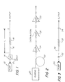
- FIG. 1 illustrates an optical fiber amplifier in accordance with the present invention.
- a pump laser 10 pumps a rare earth-doped length L of an optical fiber 16 to provide amplification in a conventional manner.
- the signal to be amplified is coupled from a terminal 12 to the fiber 16 via a conventional optical coupler 14.
- a Bragg grating 18 is provided within a guided wave portion of the doped optical fiber and preferably located near the center of the length of fiber.
- the grating is a photo induced Bragg grating that is fabricated, for example, by the techniques disclosed in the aforementioned articles to Meltz, et al or Kashgap, et al, except that the grating is not formed perpendicular to a longitudinal axis of the fiber 16. Instead, the grating is oriented at a nonperpendicular angle with respect to a longitudinal axis of the fiber. This enables light at the interaction wavelength of the grating to exit the fiber.
- the interaction wavelength of the Bragg grating is selected to correspond to a wavelength at or near the wavelength at which the spontaneous emission produced by the fiber peaks.
- Figure 4 illustrates the gain spectra of an erbium-doped fiber amplifier.
- a gain peak 40 of about 32 dB is obtained at 1532 nm, with a much reduced gain of about 24 dB at 1550 nm.
- the amplifier 3 dB bandwidth is only about 4.5 nm.
- the gain peak 40 is substantially eliminated by diverting the spontaneous emission corresponding thereto out of the fiber.
- the flattened gain spectrum indicated by dashed line 42 results, providing a 3 dB bandwidth of over 30 nm.
- An amplifier in accordance with the present invention is particularly useful in a wave division multiplexed, multi-channel signal distribution system using cascaded amplifiers along the distribution path.
- a headend 20 provides a multiplex of communication signals to an optical fiber distribution path 22.
- a plurality of amplifiers 24, 26, 28 are cascaded within the distribution path.
- Each of the amplifiers is a doped optical fiber amplifier with an in-fiber grating as illustrated in Figure 1.
- the flattened gain curve allows cascaded amplifiers to operate without premature saturation in the region of the gain peak. This, coupled with the favorable gain bandwidth of the amplifiers, provides efficient signal distribution.
- the in-fiber Bragg grating of the present invention can also be used to flatten the gain of a laser.
- a pump laser 30 is used to pump a rare earth-doped fiber 36 residing between reflectors 32, 34 that form a laser cavity.
- An in-fiber Bragg grating 38 equivalent to the grating 18 illustrated in Figure 1, diverts excess spontaneous emission from fiber 36 to flatten the gain slope of the laser. This is particularly advantageous in a tunable laser, in order to effect continuous and uniform tuning.
- an in-fiber Bragg grating which can be formed using photorefractive techniques, is oriented at a nonperpendicular angle with respect to a longitudinal axis of the doped fiber to divert peak spontaneous emission therefrom.
Claims (9)
- Amplificateur optique à fibre, présentant une pente de gain aplanie, comprenant:caractérisé en ce queune longueur de fibre optique dopée (16, 36) pour y amplifier un signal optique lorsqu'elle est pompée avec une source (10, 30) d'énergie de pompage, la fibre (16, 36) produisant une émission spontanée lorsqu'elle est pompée, etun treillis de Bragg (18, 38) orienté selon un angle non perpendiculaire par rapport à un axe longitudinal de la fibre (16, 36) et présentant une longueur d'onde d'interaction sélectionnée pour aplanir la pente de gain de l'amplificateur en déviant de la fibre (16, 36) une émission spontanée en excès,le treillis de Bragg (18, 38) est agencé dans une partie d'onde guidée de la fibre optique dopée.
- Amplificateur suivant la revendication 1, caractérisé en ce que la longueur d'onde d'interaction est sélectionnée pour correspondre à une longueur d'onde à l'endroit ou proche de la longueur d'onde à laquelle culmine (40) l'émission spontanée produite par la fibre précitée.
- Amplificateur suivant la revendication 1 ou 2, caractérisé en ce que la treillis (18, 38) est un treillis de Bragg photo-induit, dans la partie d'onde guidée (16, 36).
- Amplificateur suivant l'une des revendications précédentes, caractérisé en ce que l'angle non perpendiculaire est un angle , dans lequel
- Amplificateur suivant l'une des revendications précédentes, caractérisé en ce que la fibre (16, 36) est une fibre dopée à l'erbium et en ce que la longueur d'onde d'interaction est d'approximativement 1.532 nm.
- Système de communication à fibre optique, comprenant :un trajet de transmission optique, etune pluralité d'amplificateurs optiques (24, 26, 28) montés en cascade en série le long du trajet, les amplificateurs optiques (24, 26, 28) étant des amplificateurs (24, 26, 28) suivant l'une des revendications 1 à 5.
- Système de communication suivant la revendication 6, caractérisé en ce que les amplificateurs optiques (24, 26, 28) sont des amplificateurs à fibre à l'erbium et en ce que la longueur d'onde d'interaction des treillis précités est d'approximativement 1.532 nm.
- Laser à fibre optique comprenant une pente de gain aplanie, comportant :un amplificateur optique à fibre (36, 38) suivant l'une des revendications 1 à 5, etune cavité de laser (32, 34) comprenant l'amplificateur optique à fibre (36, 38).
- Procédé pour aplanir la pente de gain d'un amplificateur à fibre optique, comprenant les étapes de :caractérisé en ce queprévoir une longueur de fibre optique dopée (16, 36) pour y amplifier un signal optique lorsqu'elle est pompée avec une source d'énergie de pompage (10, 30), la fibre (16, 36) produisant une émission spontanée lorsqu'elle est pompée, etdévier de la fibre une émission spontanée en excès en utilisant un treillis de Bragg (18, 38), le treillis (18, 38) présentant une longueur d'onde d'interaction qui est sélectionnée pour correspondre à une longueur d'onde à l'endroit, ou proche, de la longueur d'onde à laquelle culmine (40) l'émission spontanée produite par la fibre, le treillis étant orienté selon un angle non perpendiculaire par rapport à un axe longitudinal de la fibre pour procurer un trajet de sortie de la fibre pour l'émission spontanée en excès,le treillis de Bragg est situé dans une partie d'onde guidée de la fibre (16, 36).
Applications Claiming Priority (2)
| Application Number | Priority Date | Filing Date | Title |
|---|---|---|---|
| US919921 | 1992-07-27 | ||
| US07/919,921 US5271024A (en) | 1992-07-27 | 1992-07-27 | Optical fiber amplifier and laser with flattened gain slope |
Publications (2)
| Publication Number | Publication Date |
|---|---|
| EP0582860A1 EP0582860A1 (fr) | 1994-02-16 |
| EP0582860B1 true EP0582860B1 (fr) | 1998-10-14 |
Family
ID=25442872
Family Applications (1)
| Application Number | Title | Priority Date | Filing Date |
|---|---|---|---|
| EP93111580A Expired - Lifetime EP0582860B1 (fr) | 1992-07-27 | 1993-07-20 | Amplificateur et laser à fibre optique avec profil de gain uniforme |
Country Status (10)
| Country | Link |
|---|---|
| US (1) | US5271024A (fr) |
| EP (1) | EP0582860B1 (fr) |
| JP (1) | JPH06177467A (fr) |
| AT (1) | ATE172329T1 (fr) |
| CA (1) | CA2101364C (fr) |
| DE (1) | DE69321532T2 (fr) |
| DK (1) | DK0582860T3 (fr) |
| ES (1) | ES2121904T3 (fr) |
| MX (1) | MX9304491A (fr) |
| TW (1) | TW227080B (fr) |
Families Citing this family (85)
| Publication number | Priority date | Publication date | Assignee | Title |
|---|---|---|---|---|
| GB9007912D0 (en) * | 1990-04-06 | 1990-06-06 | British Telecomm | A method of forming a refractive index grating in an optical waveguide |
| US5367588A (en) * | 1992-10-29 | 1994-11-22 | Her Majesty The Queen In Right Of Canada, As Represented By The Minister Of Communications | Method of fabricating Bragg gratings using a silica glass phase grating mask and mask used by same |
| US5104209A (en) * | 1991-02-19 | 1992-04-14 | Her Majesty The Queen In Right Of Canada, As Represented By The Minister Of Communications | Method of creating an index grating in an optical fiber and a mode converter using the index grating |
| US5478371A (en) * | 1992-05-05 | 1995-12-26 | At&T Corp. | Method for producing photoinduced bragg gratings by irradiating a hydrogenated glass body in a heated state |
| AU685747B2 (en) * | 1992-06-01 | 1998-01-29 | British Telecommunications Public Limited Company | Filter with preselected attenuation/wavelength characteristic |
| US5579143A (en) * | 1993-06-04 | 1996-11-26 | Ciena Corporation | Optical system with tunable in-fiber gratings |
| US5600473A (en) * | 1993-06-04 | 1997-02-04 | Ciena Corporation | Optical amplifier systems with add/drop multiplexing |
| US5475780A (en) * | 1993-06-17 | 1995-12-12 | At&T Corp. | Optical waveguiding component comprising a band-pass filter |
| GB2280515B (en) * | 1993-07-28 | 1996-06-19 | Northern Telecom Ltd | Optical waveguide amplifier |
| US5406404A (en) * | 1993-11-02 | 1995-04-11 | At&T Corp. | Method of mitigating gain peaking using a chain of fiber amplifiers |
| USH1813H (en) * | 1993-11-19 | 1999-11-02 | Kersey; Alan D. | Spectrally-selective fiber transmission filter system |
| US5841797A (en) * | 1994-06-28 | 1998-11-24 | Ventrudo; Brian F. | Apparatus for stabilizing multiple laser sources and their application |
| US5589684A (en) * | 1994-06-28 | 1996-12-31 | Sdl, Inc. | Multiple diode lasers stabilized with a fiber grating |
| US5485481A (en) * | 1994-06-28 | 1996-01-16 | Seastar Optics Inc. | Fibre-grating-stabilized diode laser |
| JP2760482B2 (ja) * | 1994-08-18 | 1998-05-28 | 松下電器産業株式会社 | 光ファイバ増幅器および光ファイバ伝送システム |
| US5499134A (en) * | 1994-08-24 | 1996-03-12 | Imra America | Optical pulse amplification using chirped Bragg gratings |
| US5504772A (en) * | 1994-09-09 | 1996-04-02 | Deacon Research | Laser with electrically-controlled grating reflector |
| US5657406A (en) * | 1994-09-23 | 1997-08-12 | United Technologies Corporation | Efficient optical wavelength multiplexer/de-multiplexer |
| GB9420132D0 (en) * | 1994-10-05 | 1994-11-16 | Norhern Telecom Limited | Optical amplifiers |
| US5450427A (en) * | 1994-10-21 | 1995-09-12 | Imra America, Inc. | Technique for the generation of optical pulses in modelocked lasers by dispersive control of the oscillation pulse width |
| US5541766A (en) * | 1994-11-30 | 1996-07-30 | At&T Corp. | Gain control for optically amplified systems |
| US6233077B1 (en) | 1995-05-11 | 2001-05-15 | Ciena Corporation | Remodulating channel selectors for WDM optical communication systems |
| US9191117B2 (en) * | 1995-05-11 | 2015-11-17 | Ciena Corporation | High-speed optical transponder systems |
| US5504609A (en) * | 1995-05-11 | 1996-04-02 | Ciena Corporation | WDM optical communication system with remodulators |
| FR2737051B1 (fr) * | 1995-07-20 | 1997-10-10 | Allain Jean Yves | Dispositif d'emission laser a fibre optique dopee et utilisation de ce dispositif en reflectometrie |
| US5875272A (en) * | 1995-10-27 | 1999-02-23 | Arroyo Optics, Inc. | Wavelength selective optical devices |
| AU711424B2 (en) | 1995-08-29 | 1999-10-14 | Arroyo Optics, Inc. | Wavelength selective grating assisted optical couplers |
| US6236782B1 (en) | 1995-08-29 | 2001-05-22 | Arroyo Optics, Inc. | Grating assisted coupler devices |
| US5710659A (en) * | 1995-12-19 | 1998-01-20 | Lucent Technologies Inc. | Low tilt, high gain fiber amplifier |
| US5668821A (en) * | 1996-01-16 | 1997-09-16 | Lucent Technologies Inc. | Optical systems and devices employing spectrally flattened amplified spontaneous emission |
| JP3512050B2 (ja) * | 1996-06-11 | 2004-03-29 | 住友電気工業株式会社 | 光フィルタおよび光伝送システム |
| US5838851A (en) * | 1996-06-24 | 1998-11-17 | Trw Inc. | Optical-loop signal processing using reflection mechanisms |
| US6169830B1 (en) | 1996-08-26 | 2001-01-02 | Arroyo Optics, Inc. | Methods of fabricating grating assisted coupler devices |
| US6052393A (en) | 1996-12-23 | 2000-04-18 | The Regents Of The University Of Michigan | Broadband Sagnac Raman amplifiers and cascade lasers |
| US5892615A (en) * | 1997-03-17 | 1999-04-06 | Sdl, Inc. | Output power enhancement in optical fiber lasers |
| EP0883255A3 (fr) * | 1997-06-05 | 2002-01-09 | Nortel Networks Limited | Système de transmission WDM avec amplificateurs optiques |
| US5982964A (en) * | 1997-06-30 | 1999-11-09 | Uniphase Corporation | Process for fabrication and independent tuning of multiple integrated optical directional couplers on a single substrate |
| US6151157A (en) * | 1997-06-30 | 2000-11-21 | Uniphase Telecommunications Products, Inc. | Dynamic optical amplifier |
| US5915052A (en) * | 1997-06-30 | 1999-06-22 | Uniphase Telecommunications Products, Inc. | Loop status monitor for determining the amplitude of the signal components of a multi-wavelength optical beam |
| US6370290B1 (en) | 1997-09-19 | 2002-04-09 | Uniphase Corporation | Integrated wavelength-select transmitter |
| US6031849A (en) * | 1997-11-14 | 2000-02-29 | Jds Uniphase Corporation | High power three level fiber laser and method of making same |
| US6020986A (en) * | 1997-11-21 | 2000-02-01 | Jds Uniphase Corporation | Programmable add-drop module for use in an optical circuit |
| US6122299A (en) * | 1997-12-31 | 2000-09-19 | Sdl, Inc. | Angled distributed reflector optical device with enhanced light confinement |
| AUPP218198A0 (en) * | 1998-03-04 | 1998-03-26 | University Of Sydney, The | Ultra-broadband low-noise gain-flattened rare-earth-doped fibre amplifier |
| AU748401C (en) * | 1998-03-04 | 2003-07-24 | University Of Sydney, The | Ultra-broadband low-noise gain-flattened rare-earth-doped fibre amplifier |
| US6374006B1 (en) | 1998-03-20 | 2002-04-16 | Xtera Communications, Inc. | Chirped period gratings for raman amplification in circulator loop cavities |
| US6693737B2 (en) | 1998-03-24 | 2004-02-17 | Xtera Communications, Inc. | Dispersion compensating nonlinear polarization amplifiers |
| US6600592B2 (en) | 1998-03-24 | 2003-07-29 | Xtera Communications, Inc. | S+ band nonlinear polarization amplifiers |
| US6631025B2 (en) | 2000-01-12 | 2003-10-07 | Xtera Communications, Inc. | Low-noise distributed Raman amplifier using bi-directional pumping using multiple Raman orders |
| US6356384B1 (en) | 1998-03-24 | 2002-03-12 | Xtera Communications Inc. | Broadband amplifier and communication system |
| US6760148B2 (en) | 1998-03-24 | 2004-07-06 | Xtera Communications, Inc. | Nonlinear polarization amplifiers in nonzero dispersion shifted fiber |
| US6282340B1 (en) * | 1998-04-23 | 2001-08-28 | The Furukawa Electric Co., Ltd. | Light wavelength tuning device and light source optical demultiplexer and wavelength division multiplexed optical communication system using the tuning device |
| US6148011A (en) * | 1998-05-01 | 2000-11-14 | Institut National D'optique | Wavelength sliced self-seeded pulsed laser |
| DE19825037C2 (de) * | 1998-06-04 | 2000-12-21 | Zeiss Carl Jena Gmbh | Kurzkohärente Lichtquelle und deren Verwendung |
| US6359725B1 (en) | 1998-06-16 | 2002-03-19 | Xtera Communications, Inc. | Multi-stage optical amplifier and broadband communication system |
| ATE488037T1 (de) | 1998-06-16 | 2010-11-15 | Xtera Communications Inc | Dispersionskompensierendes und verstärkendes optisches element |
| US6574037B2 (en) | 1998-06-16 | 2003-06-03 | Xtera Communications, Inc. | All band amplifier |
| US6335820B1 (en) | 1999-12-23 | 2002-01-01 | Xtera Communications, Inc. | Multi-stage optical amplifier and broadband communication system |
| US6885498B2 (en) | 1998-06-16 | 2005-04-26 | Xtera Communications, Inc. | Multi-stage optical amplifier and broadband communication system |
| US6567430B1 (en) | 1998-09-21 | 2003-05-20 | Xtera Communications, Inc. | Raman oscillator including an intracavity filter and amplifiers utilizing same |
| US6310990B1 (en) | 2000-03-16 | 2001-10-30 | Cidra Corporation | Tunable optical structure featuring feedback control |
| JP2000180640A (ja) * | 1998-12-16 | 2000-06-30 | Mitsubishi Cable Ind Ltd | ゲインイコライザ、光増幅装置および光ファイバ通信システム |
| KR100342190B1 (ko) | 1999-01-14 | 2002-06-27 | 윤종용 | 이득 평탄화 광섬유증폭기 |
| DE19926811A1 (de) * | 1999-03-22 | 2000-09-28 | Claude Stricker | Lichtquelle für die optische Informationsübertragung |
| JP3784585B2 (ja) * | 1999-08-26 | 2006-06-14 | 富士通株式会社 | 光ファイバ伝送のための方法、光デバイス及びシステム |
| US6404539B1 (en) | 1999-11-09 | 2002-06-11 | Giorgos Kotrotsios | Light source for optical data transmission |
| WO2001037458A1 (fr) * | 1999-11-16 | 2001-05-25 | Smith Peter W E | Amplificateurs dynamiques a fibres dopes a l'erbium a egalisation de puissance utilisant des filtres de crete de transmission fondes sur des reseaux de diffraction de bragg a fibres a compression lineaire apodises |
| AU2001264548A1 (en) | 2000-02-14 | 2001-10-23 | Xtera Communications, Inc. | Nonlinear optical loop mirror |
| DE60138935D1 (de) * | 2000-02-23 | 2009-07-23 | Fujitsu Ltd | Optischer Verstärker |
| AU2001274096A1 (en) * | 2000-06-20 | 2002-01-02 | Evotec Oai Ag | Fiber laser |
| US20020090170A1 (en) * | 2000-11-27 | 2002-07-11 | Bendett Mark P. | Apparatus and method for integrated photonic devices having adjustable gain |
| US6707072B2 (en) | 2001-02-28 | 2004-03-16 | The Furukawa Electric Co., Ltd. | Semiconductor laser module |
| US6456765B1 (en) * | 2001-04-30 | 2002-09-24 | Raytheon Company | Apparatus for separating and/or combining optical signals, and methods of making and operating it |
| US6587259B2 (en) | 2001-07-27 | 2003-07-01 | Xtera Communications, Inc. | System and method for controlling noise figure |
| CA2396650C (fr) * | 2001-08-31 | 2010-05-04 | Fujikura Ltd. | Composant optique de type a fibre |
| US6594071B1 (en) | 2001-10-02 | 2003-07-15 | Xtera Communications, Inc. | Method and apparatus for amplifier control |
| US6813405B1 (en) * | 2002-03-29 | 2004-11-02 | Teem Photonics | Compact apparatus and method for integrated photonic devices having folded directional couplers |
| US20030185514A1 (en) * | 2002-03-29 | 2003-10-02 | Bendett Mark P. | Method and apparatus for tapping a waveguide on a substrate |
| US7095772B1 (en) * | 2003-05-22 | 2006-08-22 | Research Foundation Of The University Of Central Florida, Inc. | Extreme chirped/stretched pulsed amplification and laser |
| US7209283B2 (en) * | 2004-04-07 | 2007-04-24 | Avago Technologies Fiber Ip (Singapore) Pte. Ltd. | Compact optical amplifier with a flattened gain profile |
| US7197209B2 (en) * | 2004-07-15 | 2007-03-27 | Bae Systems Information And Electronic Systems Integration Inc. | Optical distribution system for sensors |
| TWI326544B (en) | 2006-11-15 | 2010-06-21 | Ind Tech Res Inst | An intelligent heterogeneous network packet dispatcher methodology |
| TWI513993B (zh) | 2013-03-26 | 2015-12-21 | Ind Tech Res Inst | 三軸磁場感測器、製作磁場感測結構的方法與磁場感測電路 |
| US20220337015A1 (en) * | 2019-08-21 | 2022-10-20 | Ofs Fitel, Llc | Optical fiber amplifier with distributed gain flattening |
| CN113497403B (zh) * | 2020-04-08 | 2022-08-26 | 华为技术有限公司 | 一种光纤、光放大器及光通信系统 |
Family Cites Families (7)
| Publication number | Priority date | Publication date | Assignee | Title |
|---|---|---|---|---|
| US4786132A (en) * | 1987-03-31 | 1988-11-22 | Lytel Corporation | Hybrid distributed bragg reflector laser |
| US4911516A (en) * | 1989-02-27 | 1990-03-27 | General Electric Company | Optical device with mode selecting grating |
| US5115338A (en) * | 1990-05-30 | 1992-05-19 | At&T Bell Laboratories | Multi-stage optical amplifier |
| US5134620A (en) * | 1990-11-20 | 1992-07-28 | General Instrument Corporation | Laser with longitudinal mode selection |
| US5151908A (en) * | 1990-11-20 | 1992-09-29 | General Instrument Corporation | Laser with longitudinal mode selection |
| US5166940A (en) * | 1991-06-04 | 1992-11-24 | The Charles Stark Draper Laboratory, Inc. | Fiber laser and method of making same |
| US5159601A (en) * | 1991-07-17 | 1992-10-27 | General Instrument Corporation | Method for producing a tunable erbium fiber laser |
-
1992
- 1992-07-27 US US07/919,921 patent/US5271024A/en not_active Expired - Lifetime
-
1993
- 1993-07-20 EP EP93111580A patent/EP0582860B1/fr not_active Expired - Lifetime
- 1993-07-20 DE DE69321532T patent/DE69321532T2/de not_active Expired - Lifetime
- 1993-07-20 AT AT93111580T patent/ATE172329T1/de not_active IP Right Cessation
- 1993-07-20 ES ES93111580T patent/ES2121904T3/es not_active Expired - Lifetime
- 1993-07-20 DK DK93111580T patent/DK0582860T3/da active
- 1993-07-26 MX MX9304491A patent/MX9304491A/es not_active IP Right Cessation
- 1993-07-27 CA CA002101364A patent/CA2101364C/fr not_active Expired - Fee Related
- 1993-07-27 JP JP5203764A patent/JPH06177467A/ja active Pending
- 1993-09-07 TW TW082107292A patent/TW227080B/zh active
Also Published As
| Publication number | Publication date |
|---|---|
| MX9304491A (es) | 1994-04-29 |
| US5271024A (en) | 1993-12-14 |
| EP0582860A1 (fr) | 1994-02-16 |
| CA2101364A1 (fr) | 1994-01-28 |
| TW227080B (fr) | 1994-07-21 |
| DK0582860T3 (da) | 1999-06-23 |
| DE69321532T2 (de) | 1999-05-06 |
| ES2121904T3 (es) | 1998-12-16 |
| DE69321532D1 (de) | 1998-11-19 |
| CA2101364C (fr) | 2002-09-17 |
| ATE172329T1 (de) | 1998-10-15 |
| JPH06177467A (ja) | 1994-06-24 |
Similar Documents
| Publication | Publication Date | Title |
|---|---|---|
| EP0582860B1 (fr) | Amplificateur et laser à fibre optique avec profil de gain uniforme | |
| US5187760A (en) | Wavelength selective coupler for high power optical communications | |
| US5260823A (en) | Erbium-doped fibre amplifier with shaped spectral gain | |
| EP0651479B1 (fr) | Appareil comprenant un laser ou un amplificateur à fibre optique | |
| US6236498B1 (en) | Upgradable, gain flattened fiber amplifiers for WDM applications | |
| US5287216A (en) | Fiber amplifier with multiple pumps | |
| US5966480A (en) | Article comprising an improved cascaded optical fiber Raman device | |
| US5497265A (en) | High-power signals optical generator for telecommunication systems | |
| US5067789A (en) | Fiber optic coupling filter and amplifier | |
| US6621627B2 (en) | WDM fiber amplifiers using sampled bragg gratings | |
| WO1991018434A1 (fr) | Amplificateur a fibre dopee d'erbium et a gain spectral modifie | |
| US20020024706A1 (en) | Multiple-wavelength amplified telecommunications system with gain compensation | |
| JP3621220B2 (ja) | 光増幅器及び光導波構造 | |
| JP3382394B2 (ja) | ブラッググレーティング使用波長多重光回路 | |
| US5526174A (en) | Optical amplification system | |
| US6618192B2 (en) | High efficiency raman amplifier | |
| CA2140481A1 (fr) | Amplificteur optique a fibre optique dopee avec un fluorure et methode de fabrication de cet amplificateur | |
| Kim et al. | Design of hybrid optical amplifiers for high capacity optical transmission | |
| Bousselet et al. | + 26 dBm output power from an engineered cladding-pumped Yb-free EDFA for L-band WDM applications | |
| JP2001117126A (ja) | ラマン増幅器及びそれを用いた光ファイバ通信システム | |
| KR20010074560A (ko) | 마이크로 밴딩 장주기 광섬유 격자를 이용한 광섬유증폭기의 파장 가변 이득 평탄화용 필터 | |
| Cullen et al. | EDFA gain flattening using periodic tapered fibre filters | |
| Tanaka et al. | Low loss integrated Mach-Zehnder-interferometer-type eight-wavelength multiplexer for 1480 nm band pumping | |
| Yokota et al. | An ASE reduction filter using cascaded optical fiber grating couplers in EDFA repeater | |
| Jung et al. | Multi-wavelength fiber laser using a single multicore erbium doped fiber |
Legal Events
| Date | Code | Title | Description |
|---|---|---|---|
| PUAI | Public reference made under article 153(3) epc to a published international application that has entered the european phase |
Free format text: ORIGINAL CODE: 0009012 |
|
| AK | Designated contracting states |
Kind code of ref document: A1 Designated state(s): AT BE CH DE DK ES FR GB GR IE IT LI NL SE |
|
| RAP1 | Party data changed (applicant data changed or rights of an application transferred) |
Owner name: GI CORPORATION |
|
| 17P | Request for examination filed |
Effective date: 19940726 |
|
| RAP1 | Party data changed (applicant data changed or rights of an application transferred) |
Owner name: GENERAL INSTRUMENT CORPORATION OF DELAWARE |
|
| 17Q | First examination report despatched |
Effective date: 19951222 |
|
| GRAG | Despatch of communication of intention to grant |
Free format text: ORIGINAL CODE: EPIDOS AGRA |
|
| GRAG | Despatch of communication of intention to grant |
Free format text: ORIGINAL CODE: EPIDOS AGRA |
|
| GRAH | Despatch of communication of intention to grant a patent |
Free format text: ORIGINAL CODE: EPIDOS IGRA |
|
| GRAH | Despatch of communication of intention to grant a patent |
Free format text: ORIGINAL CODE: EPIDOS IGRA |
|
| GRAA | (expected) grant |
Free format text: ORIGINAL CODE: 0009210 |
|
| AK | Designated contracting states |
Kind code of ref document: B1 Designated state(s): AT BE CH DE DK ES FR GB GR IE IT LI NL SE |
|
| REF | Corresponds to: |
Ref document number: 172329 Country of ref document: AT Date of ref document: 19981015 Kind code of ref document: T |
|
| REG | Reference to a national code |
Ref country code: CH Ref legal event code: EP |
|
| RAP2 | Party data changed (patent owner data changed or rights of a patent transferred) |
Owner name: NEXTLEVEL SYSTEMS, INC. |
|
| REG | Reference to a national code |
Ref country code: CH Ref legal event code: NV Representative=s name: KIRKER & CIE SA |
|
| RAP2 | Party data changed (patent owner data changed or rights of a patent transferred) |
Owner name: GENERAL INSTRUMENT CORPORATION |
|
| REF | Corresponds to: |
Ref document number: 69321532 Country of ref document: DE Date of ref document: 19981119 |
|
| REG | Reference to a national code |
Ref country code: ES Ref legal event code: FG2A Ref document number: 2121904 Country of ref document: ES Kind code of ref document: T3 |
|
| REG | Reference to a national code |
Ref country code: IE Ref legal event code: FG4D |
|
| NLT2 | Nl: modifications (of names), taken from the european patent patent bulletin |
Owner name: GENERAL INSTRUMENT CORPORATION;NEXTLEVEL SYSTEMS, |
|
| ET | Fr: translation filed | ||
| REG | Reference to a national code |
Ref country code: DK Ref legal event code: T3 |
|
| PLBE | No opposition filed within time limit |
Free format text: ORIGINAL CODE: 0009261 |
|
| STAA | Information on the status of an ep patent application or granted ep patent |
Free format text: STATUS: NO OPPOSITION FILED WITHIN TIME LIMIT |
|
| 26N | No opposition filed | ||
| REG | Reference to a national code |
Ref country code: GB Ref legal event code: IF02 |
|
| PGFP | Annual fee paid to national office [announced via postgrant information from national office to epo] |
Ref country code: DK Payment date: 20070731 Year of fee payment: 15 |
|
| PGFP | Annual fee paid to national office [announced via postgrant information from national office to epo] |
Ref country code: GR Payment date: 20070730 Year of fee payment: 15 |
|
| PGFP | Annual fee paid to national office [announced via postgrant information from national office to epo] |
Ref country code: NL Payment date: 20080724 Year of fee payment: 16 Ref country code: IT Payment date: 20080728 Year of fee payment: 16 Ref country code: AT Payment date: 20080702 Year of fee payment: 16 |
|
| PGFP | Annual fee paid to national office [announced via postgrant information from national office to epo] |
Ref country code: SE Payment date: 20080729 Year of fee payment: 16 Ref country code: BE Payment date: 20080818 Year of fee payment: 16 |
|
| REG | Reference to a national code |
Ref country code: DK Ref legal event code: EBP |
|
| PG25 | Lapsed in a contracting state [announced via postgrant information from national office to epo] |
Ref country code: GR Free format text: LAPSE BECAUSE OF NON-PAYMENT OF DUE FEES Effective date: 20090204 |
|
| PG25 | Lapsed in a contracting state [announced via postgrant information from national office to epo] |
Ref country code: DK Free format text: LAPSE BECAUSE OF NON-PAYMENT OF DUE FEES Effective date: 20080731 |
|
| PGFP | Annual fee paid to national office [announced via postgrant information from national office to epo] |
Ref country code: IE Payment date: 20090728 Year of fee payment: 17 Ref country code: ES Payment date: 20090727 Year of fee payment: 17 |
|
| BERE | Be: lapsed |
Owner name: *GENERAL INSTRUMENT CORP. Effective date: 20090731 |
|
| EUG | Se: european patent has lapsed | ||
| NLV4 | Nl: lapsed or anulled due to non-payment of the annual fee |
Effective date: 20100201 |
|
| PGFP | Annual fee paid to national office [announced via postgrant information from national office to epo] |
Ref country code: FR Payment date: 20100311 Year of fee payment: 17 |
|
| PG25 | Lapsed in a contracting state [announced via postgrant information from national office to epo] |
Ref country code: BE Free format text: LAPSE BECAUSE OF NON-PAYMENT OF DUE FEES Effective date: 20090731 Ref country code: AT Free format text: LAPSE BECAUSE OF NON-PAYMENT OF DUE FEES Effective date: 20090720 |
|
| PGFP | Annual fee paid to national office [announced via postgrant information from national office to epo] |
Ref country code: CH Payment date: 20100726 Year of fee payment: 18 |
|
| PGFP | Annual fee paid to national office [announced via postgrant information from national office to epo] |
Ref country code: DE Payment date: 20100728 Year of fee payment: 18 |
|
| PGFP | Annual fee paid to national office [announced via postgrant information from national office to epo] |
Ref country code: GB Payment date: 20100726 Year of fee payment: 18 |
|
| PG25 | Lapsed in a contracting state [announced via postgrant information from national office to epo] |
Ref country code: IT Free format text: LAPSE BECAUSE OF NON-PAYMENT OF DUE FEES Effective date: 20090720 |
|
| REG | Reference to a national code |
Ref country code: FR Ref legal event code: ST Effective date: 20110331 |
|
| REG | Reference to a national code |
Ref country code: IE Ref legal event code: MM4A |
|
| PG25 | Lapsed in a contracting state [announced via postgrant information from national office to epo] |
Ref country code: SE Free format text: LAPSE BECAUSE OF NON-PAYMENT OF DUE FEES Effective date: 20090721 Ref country code: FR Free format text: LAPSE BECAUSE OF NON-PAYMENT OF DUE FEES Effective date: 20100802 |
|
| PG25 | Lapsed in a contracting state [announced via postgrant information from national office to epo] |
Ref country code: IE Free format text: LAPSE BECAUSE OF NON-PAYMENT OF DUE FEES Effective date: 20100720 |
|
| REG | Reference to a national code |
Ref country code: ES Ref legal event code: FD2A Effective date: 20110818 |
|
| PG25 | Lapsed in a contracting state [announced via postgrant information from national office to epo] |
Ref country code: ES Free format text: LAPSE BECAUSE OF NON-PAYMENT OF DUE FEES Effective date: 20100721 |
|
| REG | Reference to a national code |
Ref country code: CH Ref legal event code: PL |
|
| GBPC | Gb: european patent ceased through non-payment of renewal fee |
Effective date: 20110720 |
|
| PG25 | Lapsed in a contracting state [announced via postgrant information from national office to epo] |
Ref country code: LI Free format text: LAPSE BECAUSE OF NON-PAYMENT OF DUE FEES Effective date: 20110731 Ref country code: DE Free format text: LAPSE BECAUSE OF NON-PAYMENT OF DUE FEES Effective date: 20120201 Ref country code: CH Free format text: LAPSE BECAUSE OF NON-PAYMENT OF DUE FEES Effective date: 20110731 |
|
| REG | Reference to a national code |
Ref country code: DE Ref legal event code: R119 Ref document number: 69321532 Country of ref document: DE Effective date: 20120201 |
|
| PG25 | Lapsed in a contracting state [announced via postgrant information from national office to epo] |
Ref country code: GB Free format text: LAPSE BECAUSE OF NON-PAYMENT OF DUE FEES Effective date: 20110720 |
|
| PG25 | Lapsed in a contracting state [announced via postgrant information from national office to epo] |
Ref country code: NL Free format text: LAPSE BECAUSE OF NON-PAYMENT OF DUE FEES Effective date: 20100201 |