EP0582394A1 - Method of incinerating waste in a cement kiln plant - Google Patents
Method of incinerating waste in a cement kiln plant Download PDFInfo
- Publication number
- EP0582394A1 EP0582394A1 EP93305497A EP93305497A EP0582394A1 EP 0582394 A1 EP0582394 A1 EP 0582394A1 EP 93305497 A EP93305497 A EP 93305497A EP 93305497 A EP93305497 A EP 93305497A EP 0582394 A1 EP0582394 A1 EP 0582394A1
- Authority
- EP
- European Patent Office
- Prior art keywords
- chamber
- calciner
- waste
- decomposition
- raw meal
- Prior art date
- Legal status (The legal status is an assumption and is not a legal conclusion. Google has not performed a legal analysis and makes no representation as to the accuracy of the status listed.)
- Granted
Links
Images

Classifications
-
- C—CHEMISTRY; METALLURGY
- C04—CEMENTS; CONCRETE; ARTIFICIAL STONE; CERAMICS; REFRACTORIES
- C04B—LIME, MAGNESIA; SLAG; CEMENTS; COMPOSITIONS THEREOF, e.g. MORTARS, CONCRETE OR LIKE BUILDING MATERIALS; ARTIFICIAL STONE; CERAMICS; REFRACTORIES; TREATMENT OF NATURAL STONE
- C04B7/00—Hydraulic cements
- C04B7/36—Manufacture of hydraulic cements in general
- C04B7/43—Heat treatment, e.g. precalcining, burning, melting; Cooling
- C04B7/434—Preheating with addition of fuel, e.g. calcining
-
- F—MECHANICAL ENGINEERING; LIGHTING; HEATING; WEAPONS; BLASTING
- F23—COMBUSTION APPARATUS; COMBUSTION PROCESSES
- F23G—CREMATION FURNACES; CONSUMING WASTE PRODUCTS BY COMBUSTION
- F23G5/00—Incineration of waste; Incinerator constructions; Details, accessories or control therefor
- F23G5/08—Incineration of waste; Incinerator constructions; Details, accessories or control therefor having supplementary heating
-
- F—MECHANICAL ENGINEERING; LIGHTING; HEATING; WEAPONS; BLASTING
- F23—COMBUSTION APPARATUS; COMBUSTION PROCESSES
- F23G—CREMATION FURNACES; CONSUMING WASTE PRODUCTS BY COMBUSTION
- F23G2206/00—Waste heat recuperation
- F23G2206/20—Waste heat recuperation using the heat in association with another installation
- F23G2206/201—Waste heat recuperation using the heat in association with another installation with an industrial furnace
-
- Y—GENERAL TAGGING OF NEW TECHNOLOGICAL DEVELOPMENTS; GENERAL TAGGING OF CROSS-SECTIONAL TECHNOLOGIES SPANNING OVER SEVERAL SECTIONS OF THE IPC; TECHNICAL SUBJECTS COVERED BY FORMER USPC CROSS-REFERENCE ART COLLECTIONS [XRACs] AND DIGESTS
- Y02—TECHNOLOGIES OR APPLICATIONS FOR MITIGATION OR ADAPTATION AGAINST CLIMATE CHANGE
- Y02E—REDUCTION OF GREENHOUSE GAS [GHG] EMISSIONS, RELATED TO ENERGY GENERATION, TRANSMISSION OR DISTRIBUTION
- Y02E20/00—Combustion technologies with mitigation potential
- Y02E20/30—Technologies for a more efficient combustion or heat usage
-
- Y—GENERAL TAGGING OF NEW TECHNOLOGICAL DEVELOPMENTS; GENERAL TAGGING OF CROSS-SECTIONAL TECHNOLOGIES SPANNING OVER SEVERAL SECTIONS OF THE IPC; TECHNICAL SUBJECTS COVERED BY FORMER USPC CROSS-REFERENCE ART COLLECTIONS [XRACs] AND DIGESTS
- Y02—TECHNOLOGIES OR APPLICATIONS FOR MITIGATION OR ADAPTATION AGAINST CLIMATE CHANGE
- Y02P—CLIMATE CHANGE MITIGATION TECHNOLOGIES IN THE PRODUCTION OR PROCESSING OF GOODS
- Y02P40/00—Technologies relating to the processing of minerals
- Y02P40/10—Production of cement, e.g. improving or optimising the production methods; Cement grinding
- Y02P40/125—Fuels from renewable energy sources, e.g. waste or biomass
Definitions
- the invention relates to a method for incinerating waste during the manufacture of cement clinker, in which cement raw meal is preheated in a preheater, calcined in a calciner and burned into clinker in a kiln, for example a rotary kiln, whereafter the clinker is eventually cooled in a cooler, by which method the waste is introduced into and decomposed in a separate chamber from which gaseous products are charged to and burned in the calciner, whereas non-combustible by-products are discharged from the chamber.
- the temperature in the decomposition chamber can be controlled onto the calcining temperature of the raw meal, which is generally in the range between 830 and 880°C. If the temperature should be too low, the recarbonation process will start and elevate the temperature to its previous level, and in case of any tendency towards an excessively high temperature, the calcining degree of the raw meal will be increased.
- the invention also relates to an apparatus for carrying out the aforementioned method, which apparatus comprises a preheater, a calciner with separation cyclone, a kiln, for example a rotary kiln, and a clinker cooler as well as a separate chamber the decomposition of waste, which chamber is provided with an outlet for gaseous products being connected to the calciner, and a feed opening for waste and an outlet for unburned by-products.
- Non-decomposable by-products can be discharged during operation and may be charged to the rotary kiln. It is possible to separate products which it is not desirable to feed to the kiln, for example by magnetic separation of iron and steel parts.
- such an apparatus is characterized in that the chamber is further provided with an inlet for pre-heated/calcined raw meal connected via a splitting gate to the separation cyclone of the calciner or to another cyclone in the preheater.
- the gas outlet of the decomposition chamber of the apparatus may be in direct connection with the calciner and the chamber may be provided with an air inlet and a by-product outlet at or in the bottom.
- the decomposition chamber may be designed as a spouted bed chamber which is located immediately below the calciner, with its gas outlet being located at the top of the chamber, being in direct, open connection with the bottom of the calciner.
- the decomposition chamber may also be designed as a fluid bed chamber or it may be a rotatable drum.
- Fig. 1 shows a cement kiln plant of a generally known type comprising a preheater 1, a calciner 2 with separation cyclone 3, a rotary kiln 4 with a clinker cooler 5 and an exhaust gas filter 6.
- the actual manufacture of cement in a plant of the shown kind is effected in known manner, by cement raw meal being charged at the inlet 7 at the top of the preheater 1 and moving down through the preheater 1 in counterflow with the exhaust gases from the kiln 4 which are carried upwards through the preheater 1 and into the exhaust gas filter 6.
- the raw meal is preheated and conveyed from the preheater down into the calciner 2 where the raw meal is calcined and conveyed in suspension to the separation cyclone 3.
- the calcined raw meal is separated from the exhaust gas and carried, via the duct 8, to the rotary kiln 4 in which the raw meal is burned into clinker in known manner.
- the clinker falls down into the cooler 5 where cooling of the clinker is effected by means of air. A part of the heated cooling air is directed to the calciner 2 via the duct 9 as combustion air.
- a separate decomposition chamber 10 Under the calciner 2 there is mounted a separate decomposition chamber 10, which at its bottom is provided with air from a blower 11 and the chamber is connected at its top via an outlet 18 to the bottom of the calciner for feeding of gaseous products thereto from the decomposition in the chamber 10. Waste to be decomposed in the chamber 10 is introduced at the arrow 12.
- the outlet of the separation cyclone 3 for separated raw meal is provided with a splitting gate 13 which is capable of conducting a part of the preheated and calcined raw meal to the decomposition chamber 10 via a pipeline 14.
- a spouted bed is formed inside the chamber 10, consisting of the incoming waste from 12 and the raw meal from 14, and the waste is decomposed by means of the heat from the raw meal, and the gaseous products which flow upstream to the calciner 2, while still containing combustible constituents due to the air deficiency from the blower 11, are discharged from the chamber at the top, whereas non-combustible by-products fall down from the chamber 10 to an outlet 15, being charged away or to the rotary kiln.
- the air which is supplied to the chamber by means of the blower 11 may be preheated, possibly through a heat exchange with hot gases from the process.
- the by-products from the decomposition chamber will comprise steel wires and potentially some raw meal as well which may have been granulated in the spouted bed, but after the steel wire has been removed by means of a magnetic separator, the raw meal can be recirculated to the rotary kiln.
- Other by-products which will not have any effect on the manufactured cement may be recycled into the process and their mineral constituents may be incorporated in the manufactured clinker so that the waste which is charged to the decomposition chamber does not, in principle, leave any by-product.
- the raw meal which is introduced to the chamber will be discharged fully or partially from the chamber together with the exhaust gases, being directed to the calciner.
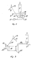
- Fig. 2 shows a part of an apparatus similar to that shown in Fig. 1, namely the calciner 2 and the splitting gate 13 with a pipeline 14 for calcined raw meal from the splitting gate 13 and to the decomposition chamber, which in this case is in the form of a fluid bed 16 with a by-product outlet 17. Also shown is the waste feed inlet 12 and the blower 11 as featured in the previous arrangement.
- Fig. 3 also shows a part of an apparatus similar to that shown in Fig. 1, but here the decomposition chamber is in the form of a rotatable drum 19 which is provided at one end with a feed inlet 12 for waste, a supply duct 14 for calcined raw meal from the splitting gate 13 and an air supply 20 from, for example, the clinker cooler 5.
- the decomposition chamber is in the form of a rotatable drum 19 which is provided at one end with a feed inlet 12 for waste, a supply duct 14 for calcined raw meal from the splitting gate 13 and an air supply 20 from, for example, the clinker cooler 5.
- the gas outlet 18 for gaseous products to the calciner and the by-product outlet 21 which may be connected directly to the inlet of the kiln so that a continuous feeding of the by-products into the clinker material is obtained.
- the calciner in apparatus of the aforementioned kind is provided with common installations for oil, coal or gas firing, it is possible, by regulating the feed rate of the usual fuel to the calciner, to control the exit temperature, and hence the degree of calcination. Hence it is possible to counteract fluctuations in the calorific value of the waste so that the output and quality of the clinker will not be influenced. Fluctuations in composition and calorific value may also influence the temperature in the decomposition chamber, but action can be taken to counter this phenomenon by leading a larger or smaller stream of calcined, hot raw meal via the splitting gate 13 down into the chamber. The temperature must be high enough to allow pyrolysis to take place, but, on the other hand, it must not be so high as to cause granulation of the raw meal.
- sewage sludge or other wet waste may also be applied in limited amounts to the decomposition chamber where drying takes place rapidly through contact with hot meal and, subsequent to this, an immediate pyrolysis.
- Waste containing a high proportion of paper can be disposed of quite easily since carbonization of paper occurs already at approximately 230°C, and no residual matter is left which cannot be burned in the calciner.
Abstract
Description
- The invention relates to a method for incinerating waste during the manufacture of cement clinker, in which cement raw meal is preheated in a preheater, calcined in a calciner and burned into clinker in a kiln, for example a rotary kiln, whereafter the clinker is eventually cooled in a cooler, by which method the waste is introduced into and decomposed in a separate chamber from which gaseous products are charged to and burned in the calciner, whereas non-combustible by-products are discharged from the chamber.
- A method of the aforementioned kind is known from the description of US patent specification 4.295.823, according to which the exhaust gases from the rotary kiln are utilized for the decomposition of waste, consisting, in the present case, of used automobile tyres. However, by using such a method it is difficult to make the kiln gases move up through the chamber in a controlled flow due to the high temperature and the utilization of kiln gases for the incineration of automobile tyres will have a disturbing effect on the draught conditions of the kiln system.
- It is the object of the present invention to remedy such disadvantages, and, according to the invention, this is achieved by a method whereby the decomposition of the waste in the chamber is effected by means of heat from preheated or calcined raw meal.
- By utilizing the heat from preheated or partially calcined raw meal, the disturbing effect on the draught conditions of the kiln system is avoided, while, at the same time, the temperature in the decomposition chamber can be controlled onto the calcining temperature of the raw meal, which is generally in the range between 830 and 880°C. If the temperature should be too low, the recarbonation process will start and elevate the temperature to its previous level, and in case of any tendency towards an excessively high temperature, the calcining degree of the raw meal will be increased.
- The invention also relates to an apparatus for carrying out the aforementioned method, which apparatus comprises a preheater, a calciner with separation cyclone, a kiln, for example a rotary kiln, and a clinker cooler as well as a separate chamber the decomposition of waste, which chamber is provided with an outlet for gaseous products being connected to the calciner, and a feed opening for waste and an outlet for unburned by-products.
- Non-decomposable by-products can be discharged during operation and may be charged to the rotary kiln. It is possible to separate products which it is not desirable to feed to the kiln, for example by magnetic separation of iron and steel parts.
- According to the invention such an apparatus is characterized in that the chamber is further provided with an inlet for pre-heated/calcined raw meal connected via a splitting gate to the separation cyclone of the calciner or to another cyclone in the preheater.
- Advantageously, the gas outlet of the decomposition chamber of the apparatus may be in direct connection with the calciner and the chamber may be provided with an air inlet and a by-product outlet at or in the bottom.
- The decomposition chamber may be designed as a spouted bed chamber which is located immediately below the calciner, with its gas outlet being located at the top of the chamber, being in direct, open connection with the bottom of the calciner.
- The decomposition chamber may also be designed as a fluid bed chamber or it may be a rotatable drum.
- The invention will now be described in further details by means of examples of an apparatus according to the invention and with reference to the accompanying drawing, being diagrammatical, and where
- Fig. 1
- shows an embodiment of an apparatus according to the invention where the decomposition chamber is a spouted bed chamber,
- Fig. 2
- shows a part of Figure 1, but where the decomposition chamber is a fluid bed chamber, and
- Fig. 3
- shows a part of Figure 1, but where the decomposition chamber is a rotatable drum
- Fig. 1 shows a cement kiln plant of a generally known type comprising a preheater 1, a
calciner 2 withseparation cyclone 3, arotary kiln 4 with aclinker cooler 5 and anexhaust gas filter 6. - The actual manufacture of cement in a plant of the shown kind is effected in known manner, by cement raw meal being charged at the
inlet 7 at the top of the preheater 1 and moving down through the preheater 1 in counterflow with the exhaust gases from thekiln 4 which are carried upwards through the preheater 1 and into theexhaust gas filter 6. In this way the raw meal is preheated and conveyed from the preheater down into thecalciner 2 where the raw meal is calcined and conveyed in suspension to theseparation cyclone 3. Here the calcined raw meal is separated from the exhaust gas and carried, via theduct 8, to therotary kiln 4 in which the raw meal is burned into clinker in known manner. The clinker falls down into thecooler 5 where cooling of the clinker is effected by means of air. A part of the heated cooling air is directed to thecalciner 2 via theduct 9 as combustion air. - Under the
calciner 2 there is mounted aseparate decomposition chamber 10, which at its bottom is provided with air from ablower 11 and the chamber is connected at its top via anoutlet 18 to the bottom of the calciner for feeding of gaseous products thereto from the decomposition in thechamber 10. Waste to be decomposed in thechamber 10 is introduced at thearrow 12. The outlet of theseparation cyclone 3 for separated raw meal is provided with a splittinggate 13 which is capable of conducting a part of the preheated and calcined raw meal to thedecomposition chamber 10 via apipeline 14. By means of the air from theblower 11, a spouted bed is formed inside thechamber 10, consisting of the incoming waste from 12 and the raw meal from 14, and the waste is decomposed by means of the heat from the raw meal, and the gaseous products which flow upstream to thecalciner 2, while still containing combustible constituents due to the air deficiency from theblower 11, are discharged from the chamber at the top, whereas non-combustible by-products fall down from thechamber 10 to anoutlet 15, being charged away or to the rotary kiln. - The air which is supplied to the chamber by means of the
blower 11 may be preheated, possibly through a heat exchange with hot gases from the process. - If the waste consists of, for example, shredded automobile tyres, the by-products from the decomposition chamber will comprise steel wires and potentially some raw meal as well which may have been granulated in the spouted bed, but after the steel wire has been removed by means of a magnetic separator, the raw meal can be recirculated to the rotary kiln. Other by-products which will not have any effect on the manufactured cement may be recycled into the process and their mineral constituents may be incorporated in the manufactured clinker so that the waste which is charged to the decomposition chamber does not, in principle, leave any by-product.
- It should be noted that the raw meal which is introduced to the chamber will be discharged fully or partially from the chamber together with the exhaust gases, being directed to the calciner.
- Fig. 2 shows a part of an apparatus similar to that shown in Fig. 1, namely the
calciner 2 and thesplitting gate 13 with apipeline 14 for calcined raw meal from the splittinggate 13 and to the decomposition chamber, which in this case is in the form of afluid bed 16 with a by-product outlet 17. Also shown is thewaste feed inlet 12 and theblower 11 as featured in the previous arrangement. - Fig. 3 also shows a part of an apparatus similar to that shown in Fig. 1, but here the decomposition chamber is in the form of a
rotatable drum 19 which is provided at one end with afeed inlet 12 for waste, asupply duct 14 for calcined raw meal from the splittinggate 13 and an air supply 20 from, for example, theclinker cooler 5. - At the opposite end of the
drum 19 are provided thegas outlet 18 for gaseous products to the calciner and the by-product outlet 21 which may be connected directly to the inlet of the kiln so that a continuous feeding of the by-products into the clinker material is obtained. - Since the calciner in apparatus of the aforementioned kind is provided with common installations for oil, coal or gas firing, it is possible, by regulating the feed rate of the usual fuel to the calciner, to control the exit temperature, and hence the degree of calcination. Hence it is possible to counteract fluctuations in the calorific value of the waste so that the output and quality of the clinker will not be influenced. Fluctuations in composition and calorific value may also influence the temperature in the decomposition chamber, but action can be taken to counter this phenomenon by leading a larger or smaller stream of calcined, hot raw meal via the splitting
gate 13 down into the chamber. The temperature must be high enough to allow pyrolysis to take place, but, on the other hand, it must not be so high as to cause granulation of the raw meal. - With a decomposition chamber on kiln plants of known design it is uncomplicated to burn pasty waste having a reasonably constant calorific value, as for example bleaching earth and sewage sludge. This simply requires that the sticky waste is dosed in an even flow to the decomposition chamber. The oil content in bleaching earth will evaporate immediately and after a short while it will be burned in the calciner. Once the bleaching earth has been relieved of its oil content, all that remains is a dry meal which will quickly be mixed with the remaining raw meal and hence incorporated as a raw material constituent corresponding to the other raw materials.
- Advantageously, sewage sludge or other wet waste may also be applied in limited amounts to the decomposition chamber where drying takes place rapidly through contact with hot meal and, subsequent to this, an immediate pyrolysis.
Waste containing a high proportion of paper can be disposed of quite easily since carbonization of paper occurs already at approximately 230°C, and no residual matter is left which cannot be burned in the calciner.
Claims (6)
- A method for incineration of waste during the manufacture of clinker, in which the cement raw meal is preheated in a preheater, calcined in a calciner, burned into clinker in a kiln, whereafter the clinker is eventually cooled in a cooler, by which method the waste is introduced into and decomposed in a separate chamber from which gaseous products are charged to and burned in the calciner whereas non-combustible by-products are discharged from the chamber,
characterized in that
the decomposition of the waste in the chamber is effected by means of heat from preheated or calcined raw meal. - An apparatus for carrying out the method according to claim 1 and comprising a preheater (1), a calciner (2) with separation cyclone (3), a kiln (4) and a clinker cooler (5) as well as a separate chamber (10, 16, 19) for decomposition of waste, which chamber (10, 16, 19) is provided with an outlet (18) for gaseous products being connected to the calciner (2), a feed opening (12) for waste and an outlet (15, 17, 21) for unburned by-products,
characterized in that
the chamber (10, 16, 19) is further provided with an inlet (14) for preheated/calcined raw meal connected via a splitting gate (13) to the separation cyclone (3) of the calciner or to another cyclone in the preheater (1). - An apparatus according to claim 2,
characterized in that
the gas outlet (18) of the decomposition chamber (10, 16, 19) is in direct connection with the calciner (2) and that the chamber (10, 16, 19) is provided with an air inlet (11, 20) as well as a by-product outlet (15, 17, 21) at or in the bottom. - An apparatus according to claim 3,
characterized in that
the decomposition chamber is designed as a spouted bed chamber (10) being located immediately below the calciner (2) and having its gas outlet (18) located at the top of the chamber (10) and in direct, open connection with the bottom of the calciner (2). - An apparatus according to claim 3,
characterized in that
the decomposition chamber is designed as a fluid bed chamber (16). - An apparatus according to claim 3,
characterized in that
the decomposition chamber is a rotatable drum (19).
Applications Claiming Priority (2)
| Application Number | Priority Date | Filing Date | Title |
|---|---|---|---|
| DK098992A DK170368B1 (en) | 1992-08-06 | 1992-08-06 | Process for incinerating waste in a cement kiln plant, as well as plant for carrying out the process |
| DK989/92 | 1992-08-06 |
Publications (2)
| Publication Number | Publication Date |
|---|---|
| EP0582394A1 true EP0582394A1 (en) | 1994-02-09 |
| EP0582394B1 EP0582394B1 (en) | 1996-09-18 |
Family
ID=8099765
Family Applications (1)
| Application Number | Title | Priority Date | Filing Date |
|---|---|---|---|
| EP93305497A Expired - Lifetime EP0582394B1 (en) | 1992-08-06 | 1993-07-14 | Method of incinerating waste in a cement kiln plant |
Country Status (9)
| Country | Link |
|---|---|
| US (1) | US5349910A (en) |
| EP (1) | EP0582394B1 (en) |
| DE (1) | DE69304842T2 (en) |
| DK (1) | DK170368B1 (en) |
| ES (1) | ES2092771T3 (en) |
| GR (1) | GR3021494T3 (en) |
| MX (1) | MX9304752A (en) |
| NO (1) | NO308790B1 (en) |
| TR (1) | TR27543A (en) |
Cited By (9)
| Publication number | Priority date | Publication date | Assignee | Title |
|---|---|---|---|---|
| WO1994029231A1 (en) * | 1993-06-03 | 1994-12-22 | F.L. Smidth & Co. A/S | Method and plant for manufacturing cement clinker |
| EP0764614A2 (en) * | 1995-09-22 | 1997-03-26 | Krupp Polysius Ag | Installation and process for manufacturing cement clinker |
| WO1998056728A1 (en) | 1997-06-11 | 1998-12-17 | Cemex, S.A. De C.V. | Method and apparatus for recovering energy from wastes by combustion in industrial furnaces |
| WO2001009548A1 (en) * | 1999-07-30 | 2001-02-08 | F.L. Smidth & Co. A/S | Method and apparatus for incineration of combustible waste during the manufacture of cement clinker |
| WO2002090283A1 (en) * | 2001-05-04 | 2002-11-14 | Polysius Ag | Plant and method for the production of cement clinker |
| EP1334954A1 (en) * | 2002-01-25 | 2003-08-13 | KHD Humboldt Wedag AG | Installation for manufacturing cement clinker |
| US6773259B1 (en) | 2003-08-05 | 2004-08-10 | Giant Cement Holding Inc. | Continuous solid waste derived fuel feed system for calciner kilns |
| US8328550B2 (en) | 2005-08-11 | 2012-12-11 | Holcim Technology Ltd. | Method and device for use of alternative fuels in clinker and cement production |
| EP3293159B1 (en) | 2016-09-09 | 2019-05-15 | Baumit Beteiligungen GmbH | Method for firing of lime or cement with synthesis gas |
Families Citing this family (14)
| Publication number | Priority date | Publication date | Assignee | Title |
|---|---|---|---|---|
| US6000937A (en) * | 1997-05-17 | 1999-12-14 | Khd Humboldt Wedag Ag | Device for distributing and/or feeding a hot flour-like material |
| DK174194B1 (en) * | 1998-02-04 | 2002-09-09 | Smidth & Co As F L | Furnace systems, as well as processes for making cement |
| DE10146418A1 (en) * | 2001-09-20 | 2003-04-17 | Kloeckner Humboldt Wedag | Process and plant for the thermal treatment of meal-like raw materials |
| US6854319B2 (en) * | 2002-09-25 | 2005-02-15 | Continental Cement Company | Methods and apparatus for providing a gas tight enclosure |
| US6892655B2 (en) * | 2002-09-25 | 2005-05-17 | Continental Cement Company, Llc | Drum transport device |
| US6807916B2 (en) * | 2002-09-25 | 2004-10-26 | Continental Cement Company, Llc | Integrated pyrolysis systems and methods |
| DE102004045510A1 (en) * | 2004-09-14 | 2006-03-30 | Polysius Ag | Process and apparatus for incinerating fuel |
| US7909895B2 (en) * | 2004-11-10 | 2011-03-22 | Enertech Environmental, Inc. | Slurry dewatering and conversion of biosolids to a renewable fuel |
| CN102057240B (en) * | 2008-06-06 | 2013-07-17 | Fl史密斯公司 | Gasification with separate calcination |
| US7972419B2 (en) * | 2008-08-07 | 2011-07-05 | Flsmidth A/S | Apparatus and method for reducing emissions resulting from raw meal grinding |
| AT510106B1 (en) * | 2010-06-22 | 2012-09-15 | Holcim Technology Ltd | METHOD FOR ASSESSING ORGANIC WASTE MATERIALS |
| CN103939912B (en) * | 2014-04-24 | 2016-01-13 | 尹小林 | Dry-process rotary kiln associated treatment is containing wet refuse bypass electrification technique as well as and system |
| CN108518998A (en) * | 2018-05-24 | 2018-09-11 | 天津金隅振兴环保科技有限公司 | The system and its technique of cement kiln, stove separation pyrolyzing disposition cyanide polluted soil |
| CN110006246B (en) * | 2019-03-22 | 2023-10-17 | 北京科太亚洲生态科技股份有限公司 | Device and method for disposing waste by preheating raw materials through rotary kiln |
Citations (5)
| Publication number | Priority date | Publication date | Assignee | Title |
|---|---|---|---|---|
| FR2249287A1 (en) * | 1973-10-30 | 1975-05-23 | Kunii Daizo | Pyrolytic refuse incinerator - reactor and adjacent regenerator are interconnected by pair of sloping shafts |
| US4295823A (en) * | 1979-04-03 | 1981-10-20 | Sumitomo Cement Co., Ltd. | Apparatus for continuously producing a cement clinker |
| FR2548660A1 (en) * | 1983-07-05 | 1985-01-11 | Folliot Albert | Process for manufacturing clinker |
| EP0140771A1 (en) * | 1983-10-28 | 1985-05-08 | FIVES-CAIL BABCOCK, Société anonyme | Process and device for the calcination of pulverized minerals |
| US4678514A (en) * | 1984-03-27 | 1987-07-07 | Dyckerhoff Engineering Gmbh | Process for the disposal of combustible refuses |
Family Cites Families (3)
| Publication number | Priority date | Publication date | Assignee | Title |
|---|---|---|---|---|
| PL122680B2 (en) * | 1980-05-17 | 1982-08-31 | Inst Przemyslu Wiazacych | Method of partial burning of lime-bearing material and apparatus therefor |
| US5220874A (en) * | 1988-03-22 | 1993-06-22 | Keating Environmental Service, Inc. | Method and apparatus for stripping volatile organic compounds from solid materials |
| US5224433A (en) * | 1988-11-23 | 1993-07-06 | Cadence Chemical Resources, Inc. | Waste fuel delivery to long kilns |
-
1992
- 1992-08-06 DK DK098992A patent/DK170368B1/en not_active IP Right Cessation
-
1993
- 1993-07-14 EP EP93305497A patent/EP0582394B1/en not_active Expired - Lifetime
- 1993-07-14 ES ES93305497T patent/ES2092771T3/en not_active Expired - Lifetime
- 1993-07-14 DE DE69304842T patent/DE69304842T2/en not_active Expired - Fee Related
- 1993-08-04 US US08/101,932 patent/US5349910A/en not_active Expired - Lifetime
- 1993-08-05 NO NO932793A patent/NO308790B1/en not_active IP Right Cessation
- 1993-08-05 MX MX9304752A patent/MX9304752A/en not_active IP Right Cessation
- 1993-08-06 TR TR00667/93A patent/TR27543A/en unknown
-
1996
- 1996-10-30 GR GR960402863T patent/GR3021494T3/en unknown
Patent Citations (5)
| Publication number | Priority date | Publication date | Assignee | Title |
|---|---|---|---|---|
| FR2249287A1 (en) * | 1973-10-30 | 1975-05-23 | Kunii Daizo | Pyrolytic refuse incinerator - reactor and adjacent regenerator are interconnected by pair of sloping shafts |
| US4295823A (en) * | 1979-04-03 | 1981-10-20 | Sumitomo Cement Co., Ltd. | Apparatus for continuously producing a cement clinker |
| FR2548660A1 (en) * | 1983-07-05 | 1985-01-11 | Folliot Albert | Process for manufacturing clinker |
| EP0140771A1 (en) * | 1983-10-28 | 1985-05-08 | FIVES-CAIL BABCOCK, Société anonyme | Process and device for the calcination of pulverized minerals |
| US4678514A (en) * | 1984-03-27 | 1987-07-07 | Dyckerhoff Engineering Gmbh | Process for the disposal of combustible refuses |
Non-Patent Citations (1)
| Title |
|---|
| CHEMICAL ABSTRACTS, vol. 101, no. 12, 17 September 1984, Columbus, Ohio, US; abstract no. 96654u, DUDA ET AL.: "Method and apparatus for partial burning of lime-containing material" page 344; column 2; * |
Cited By (13)
| Publication number | Priority date | Publication date | Assignee | Title |
|---|---|---|---|---|
| US5614016A (en) * | 1993-06-03 | 1997-03-25 | F.L. Smidth & Co. A/S | Method and plant for manufacturing cement clinker |
| WO1994029231A1 (en) * | 1993-06-03 | 1994-12-22 | F.L. Smidth & Co. A/S | Method and plant for manufacturing cement clinker |
| EP0764614A2 (en) * | 1995-09-22 | 1997-03-26 | Krupp Polysius Ag | Installation and process for manufacturing cement clinker |
| EP0764614A3 (en) * | 1995-09-22 | 1998-02-11 | Krupp Polysius Ag | Installation and process for manufacturing cement clinker |
| WO1998056728A1 (en) | 1997-06-11 | 1998-12-17 | Cemex, S.A. De C.V. | Method and apparatus for recovering energy from wastes by combustion in industrial furnaces |
| CZ298767B6 (en) * | 1999-07-30 | 2008-01-23 | F. L. Smidth & Co. A/S | Process and apparatus for burning flammable waste during manufacture of cement clinker Method for incineration of combustible waste during manufacture of cement clinker and apparatus for making the same |
| WO2001009548A1 (en) * | 1999-07-30 | 2001-02-08 | F.L. Smidth & Co. A/S | Method and apparatus for incineration of combustible waste during the manufacture of cement clinker |
| AU763616B2 (en) * | 1999-07-30 | 2003-07-31 | F.L. Smidth & Co A/S | Method and apparatus for incineration of combustible waste during the manufacture of cement clinker |
| WO2002090283A1 (en) * | 2001-05-04 | 2002-11-14 | Polysius Ag | Plant and method for the production of cement clinker |
| EP1334954A1 (en) * | 2002-01-25 | 2003-08-13 | KHD Humboldt Wedag AG | Installation for manufacturing cement clinker |
| US6773259B1 (en) | 2003-08-05 | 2004-08-10 | Giant Cement Holding Inc. | Continuous solid waste derived fuel feed system for calciner kilns |
| US8328550B2 (en) | 2005-08-11 | 2012-12-11 | Holcim Technology Ltd. | Method and device for use of alternative fuels in clinker and cement production |
| EP3293159B1 (en) | 2016-09-09 | 2019-05-15 | Baumit Beteiligungen GmbH | Method for firing of lime or cement with synthesis gas |
Also Published As
| Publication number | Publication date |
|---|---|
| NO308790B1 (en) | 2000-10-30 |
| US5349910A (en) | 1994-09-27 |
| GR3021494T3 (en) | 1997-01-31 |
| DE69304842D1 (en) | 1996-10-24 |
| ES2092771T3 (en) | 1996-12-01 |
| DK98992A (en) | 1994-02-07 |
| NO932793D0 (en) | 1993-08-05 |
| TR27543A (en) | 1995-06-07 |
| DE69304842T2 (en) | 1997-03-13 |
| DK98992D0 (en) | 1992-08-06 |
| DK170368B1 (en) | 1995-08-14 |
| EP0582394B1 (en) | 1996-09-18 |
| NO932793L (en) | 1994-02-07 |
| MX9304752A (en) | 1994-05-31 |
Similar Documents
| Publication | Publication Date | Title |
|---|---|---|
| EP0582394B1 (en) | Method of incinerating waste in a cement kiln plant | |
| US5614016A (en) | Method and plant for manufacturing cement clinker | |
| US5199987A (en) | Method of producing cement clinker | |
| JPS5911545B2 (en) | Portland cement production and waste utilization | |
| US4265670A (en) | Method and apparatus for the thermal treatment of fine-grained material with hot gases | |
| US5103743A (en) | Method and apparatus for drying solid material | |
| KR102405860B1 (en) | Sludge treatment method and cement manufacturing system | |
| US4353750A (en) | Method of firing carbonate-containing minerals | |
| US4198201A (en) | Method of and apparatus for operating industrial furnace systems | |
| US4089697A (en) | Manufacture of Portland cement | |
| CN113474312B (en) | Sludge treatment method and cement production system | |
| US4318745A (en) | Process and plant for producing hydraulic cement | |
| CA1079065A (en) | Cement calcining apparatus | |
| US5954499A (en) | Plant and method for manufacturing cement clinker | |
| JP3524002B2 (en) | Method for producing quicklime and calcined dolomite in a rotary kiln using waste plastic | |
| TWI725397B (en) | Organic sludge treatment apparatus and treatment method | |
| EP0030787B1 (en) | A kiln plant and method of operating it | |
| US4105460A (en) | Process for the endothermic calcination of raw material | |
| RU2777126C1 (en) | Sludge treatment method and cement production system | |
| GB1591768A (en) | Dry cement production process | |
| RU2175310C2 (en) | Device for production of cement clinker | |
| FI70878C (en) | FOERFARANDE FOER TILLVERKNING AV CEMENT | |
| SU1511233A1 (en) | Method of heat treatment of granulated fuel-containing materials | |
| PL139407B1 (en) | Method of partially burning a mixture of lime containingslime and meal containing combustible parzicles and apparatus therefor | |
| MXPA98007256A (en) | Plant to manufacture ceme clinker |
Legal Events
| Date | Code | Title | Description |
|---|---|---|---|
| PUAI | Public reference made under article 153(3) epc to a published international application that has entered the european phase |
Free format text: ORIGINAL CODE: 0009012 |
|
| AK | Designated contracting states |
Kind code of ref document: A1 Designated state(s): DE ES FR GB GR IT |
|
| 17P | Request for examination filed |
Effective date: 19940804 |
|
| 17Q | First examination report despatched |
Effective date: 19950816 |
|
| GRAH | Despatch of communication of intention to grant a patent |
Free format text: ORIGINAL CODE: EPIDOS IGRA |
|
| GRAH | Despatch of communication of intention to grant a patent |
Free format text: ORIGINAL CODE: EPIDOS IGRA |
|
| GRAA | (expected) grant |
Free format text: ORIGINAL CODE: 0009210 |
|
| AK | Designated contracting states |
Kind code of ref document: B1 Designated state(s): DE ES FR GB GR IT |
|
| ET | Fr: translation filed | ||
| ITF | It: translation for a ep patent filed |
Owner name: DR. ING. A. RACHELI & C. |
|
| REF | Corresponds to: |
Ref document number: 69304842 Country of ref document: DE Date of ref document: 19961024 |
|
| REG | Reference to a national code |
Ref country code: ES Ref legal event code: FG2A Ref document number: 2092771 Country of ref document: ES Kind code of ref document: T3 |
|
| REG | Reference to a national code |
Ref country code: GR Ref legal event code: FG4A Free format text: 3021494 |
|
| PLBE | No opposition filed within time limit |
Free format text: ORIGINAL CODE: 0009261 |
|
| STAA | Information on the status of an ep patent application or granted ep patent |
Free format text: STATUS: NO OPPOSITION FILED WITHIN TIME LIMIT |
|
| 26N | No opposition filed | ||
| REG | Reference to a national code |
Ref country code: GB Ref legal event code: IF02 |
|
| PGFP | Annual fee paid to national office [announced via postgrant information from national office to epo] |
Ref country code: DE Payment date: 20080717 Year of fee payment: 16 Ref country code: ES Payment date: 20080821 Year of fee payment: 16 |
|
| PGFP | Annual fee paid to national office [announced via postgrant information from national office to epo] |
Ref country code: IT Payment date: 20080731 Year of fee payment: 16 Ref country code: FR Payment date: 20080718 Year of fee payment: 16 |
|
| PGFP | Annual fee paid to national office [announced via postgrant information from national office to epo] |
Ref country code: GB Payment date: 20080716 Year of fee payment: 16 |
|
| PGFP | Annual fee paid to national office [announced via postgrant information from national office to epo] |
Ref country code: GR Payment date: 20080619 Year of fee payment: 16 |
|
| GBPC | Gb: european patent ceased through non-payment of renewal fee |
Effective date: 20090714 |
|
| REG | Reference to a national code |
Ref country code: FR Ref legal event code: ST Effective date: 20100331 |
|
| PG25 | Lapsed in a contracting state [announced via postgrant information from national office to epo] |
Ref country code: FR Free format text: LAPSE BECAUSE OF NON-PAYMENT OF DUE FEES Effective date: 20090731 |
|
| PG25 | Lapsed in a contracting state [announced via postgrant information from national office to epo] |
Ref country code: GB Free format text: LAPSE BECAUSE OF NON-PAYMENT OF DUE FEES Effective date: 20090714 |
|
| PG25 | Lapsed in a contracting state [announced via postgrant information from national office to epo] |
Ref country code: DE Free format text: LAPSE BECAUSE OF NON-PAYMENT OF DUE FEES Effective date: 20100202 |
|
| REG | Reference to a national code |
Ref country code: ES Ref legal event code: FD2A Effective date: 20090715 |
|
| PG25 | Lapsed in a contracting state [announced via postgrant information from national office to epo] |
Ref country code: GR Free format text: LAPSE BECAUSE OF NON-PAYMENT OF DUE FEES Effective date: 20100204 Ref country code: ES Free format text: LAPSE BECAUSE OF NON-PAYMENT OF DUE FEES Effective date: 20090715 |
|
| PG25 | Lapsed in a contracting state [announced via postgrant information from national office to epo] |
Ref country code: IT Free format text: LAPSE BECAUSE OF NON-PAYMENT OF DUE FEES Effective date: 20090714 |