EP0581667A1 - Screw-in glene prosthesis - Google Patents
Screw-in glene prosthesis Download PDFInfo
- Publication number
- EP0581667A1 EP0581667A1 EP93401939A EP93401939A EP0581667A1 EP 0581667 A1 EP0581667 A1 EP 0581667A1 EP 93401939 A EP93401939 A EP 93401939A EP 93401939 A EP93401939 A EP 93401939A EP 0581667 A1 EP0581667 A1 EP 0581667A1
- Authority
- EP
- European Patent Office
- Prior art keywords
- shield
- prosthesis according
- base
- multipan
- studs
- Prior art date
- Legal status (The legal status is an assumption and is not a legal conclusion. Google has not performed a legal analysis and makes no representation as to the accuracy of the status listed.)
- Ceased
Links
- 210000001991 scapula Anatomy 0.000 claims abstract description 9
- 241001653121 Glenoides Species 0.000 claims description 15
- 210000000988 bone and bone Anatomy 0.000 claims description 14
- 229920001903 high density polyethylene Polymers 0.000 claims description 3
- 239000004700 high-density polyethylene Substances 0.000 claims description 3
- 238000010079 rubber tapping Methods 0.000 claims description 2
- 238000004873 anchoring Methods 0.000 description 3
- 239000004568 cement Substances 0.000 description 3
- 238000002513 implantation Methods 0.000 description 3
- 239000007943 implant Substances 0.000 description 2
- 238000009434 installation Methods 0.000 description 2
- 238000000034 method Methods 0.000 description 2
- 235000016623 Fragaria vesca Nutrition 0.000 description 1
- 240000009088 Fragaria x ananassa Species 0.000 description 1
- 235000011363 Fragaria x ananassa Nutrition 0.000 description 1
- RTAQQCXQSZGOHL-UHFFFAOYSA-N Titanium Chemical compound [Ti] RTAQQCXQSZGOHL-UHFFFAOYSA-N 0.000 description 1
- 238000002679 ablation Methods 0.000 description 1
- 230000002950 deficient Effects 0.000 description 1
- 238000003780 insertion Methods 0.000 description 1
- 230000037431 insertion Effects 0.000 description 1
- 230000002045 lasting effect Effects 0.000 description 1
- 238000010883 osseointegration Methods 0.000 description 1
- 238000006116 polymerization reaction Methods 0.000 description 1
- 238000011084 recovery Methods 0.000 description 1
- 238000002271 resection Methods 0.000 description 1
- 230000035939 shock Effects 0.000 description 1
- 239000007787 solid Substances 0.000 description 1
- 230000003068 static effect Effects 0.000 description 1
- 229910052719 titanium Inorganic materials 0.000 description 1
- 239000010936 titanium Substances 0.000 description 1
Images


Classifications
-
- A—HUMAN NECESSITIES
- A61—MEDICAL OR VETERINARY SCIENCE; HYGIENE
- A61F—FILTERS IMPLANTABLE INTO BLOOD VESSELS; PROSTHESES; DEVICES PROVIDING PATENCY TO, OR PREVENTING COLLAPSING OF, TUBULAR STRUCTURES OF THE BODY, e.g. STENTS; ORTHOPAEDIC, NURSING OR CONTRACEPTIVE DEVICES; FOMENTATION; TREATMENT OR PROTECTION OF EYES OR EARS; BANDAGES, DRESSINGS OR ABSORBENT PADS; FIRST-AID KITS
- A61F2/00—Filters implantable into blood vessels; Prostheses, i.e. artificial substitutes or replacements for parts of the body; Appliances for connecting them with the body; Devices providing patency to, or preventing collapsing of, tubular structures of the body, e.g. stents
- A61F2/02—Prostheses implantable into the body
- A61F2/30—Joints
- A61F2/40—Joints for shoulders
- A61F2/4081—Glenoid components, e.g. cups
-
- A—HUMAN NECESSITIES
- A61—MEDICAL OR VETERINARY SCIENCE; HYGIENE
- A61B—DIAGNOSIS; SURGERY; IDENTIFICATION
- A61B17/00—Surgical instruments, devices or methods, e.g. tourniquets
- A61B17/56—Surgical instruments or methods for treatment of bones or joints; Devices specially adapted therefor
- A61B17/58—Surgical instruments or methods for treatment of bones or joints; Devices specially adapted therefor for osteosynthesis, e.g. bone plates, screws, setting implements or the like
- A61B17/68—Internal fixation devices, including fasteners and spinal fixators, even if a part thereof projects from the skin
- A61B17/84—Fasteners therefor or fasteners being internal fixation devices
- A61B17/86—Pins or screws or threaded wires; nuts therefor
-
- A—HUMAN NECESSITIES
- A61—MEDICAL OR VETERINARY SCIENCE; HYGIENE
- A61F—FILTERS IMPLANTABLE INTO BLOOD VESSELS; PROSTHESES; DEVICES PROVIDING PATENCY TO, OR PREVENTING COLLAPSING OF, TUBULAR STRUCTURES OF THE BODY, e.g. STENTS; ORTHOPAEDIC, NURSING OR CONTRACEPTIVE DEVICES; FOMENTATION; TREATMENT OR PROTECTION OF EYES OR EARS; BANDAGES, DRESSINGS OR ABSORBENT PADS; FIRST-AID KITS
- A61F2/00—Filters implantable into blood vessels; Prostheses, i.e. artificial substitutes or replacements for parts of the body; Appliances for connecting them with the body; Devices providing patency to, or preventing collapsing of, tubular structures of the body, e.g. stents
- A61F2/02—Prostheses implantable into the body
- A61F2/30—Joints
- A61F2/30767—Special external or bone-contacting surface, e.g. coating for improving bone ingrowth
- A61F2/30771—Special external or bone-contacting surface, e.g. coating for improving bone ingrowth applied in original prostheses, e.g. holes or grooves
- A61F2002/30841—Sharp anchoring protrusions for impaction into the bone, e.g. sharp pins, spikes
-
- A—HUMAN NECESSITIES
- A61—MEDICAL OR VETERINARY SCIENCE; HYGIENE
- A61F—FILTERS IMPLANTABLE INTO BLOOD VESSELS; PROSTHESES; DEVICES PROVIDING PATENCY TO, OR PREVENTING COLLAPSING OF, TUBULAR STRUCTURES OF THE BODY, e.g. STENTS; ORTHOPAEDIC, NURSING OR CONTRACEPTIVE DEVICES; FOMENTATION; TREATMENT OR PROTECTION OF EYES OR EARS; BANDAGES, DRESSINGS OR ABSORBENT PADS; FIRST-AID KITS
- A61F2/00—Filters implantable into blood vessels; Prostheses, i.e. artificial substitutes or replacements for parts of the body; Appliances for connecting them with the body; Devices providing patency to, or preventing collapsing of, tubular structures of the body, e.g. stents
- A61F2/02—Prostheses implantable into the body
- A61F2/30—Joints
- A61F2/30767—Special external or bone-contacting surface, e.g. coating for improving bone ingrowth
- A61F2/30771—Special external or bone-contacting surface, e.g. coating for improving bone ingrowth applied in original prostheses, e.g. holes or grooves
- A61F2002/3085—Special external or bone-contacting surface, e.g. coating for improving bone ingrowth applied in original prostheses, e.g. holes or grooves with a threaded, e.g. self-tapping, bone-engaging surface, e.g. external surface
-
- A—HUMAN NECESSITIES
- A61—MEDICAL OR VETERINARY SCIENCE; HYGIENE
- A61F—FILTERS IMPLANTABLE INTO BLOOD VESSELS; PROSTHESES; DEVICES PROVIDING PATENCY TO, OR PREVENTING COLLAPSING OF, TUBULAR STRUCTURES OF THE BODY, e.g. STENTS; ORTHOPAEDIC, NURSING OR CONTRACEPTIVE DEVICES; FOMENTATION; TREATMENT OR PROTECTION OF EYES OR EARS; BANDAGES, DRESSINGS OR ABSORBENT PADS; FIRST-AID KITS
- A61F2/00—Filters implantable into blood vessels; Prostheses, i.e. artificial substitutes or replacements for parts of the body; Appliances for connecting them with the body; Devices providing patency to, or preventing collapsing of, tubular structures of the body, e.g. stents
- A61F2/02—Prostheses implantable into the body
- A61F2/30—Joints
- A61F2/30767—Special external or bone-contacting surface, e.g. coating for improving bone ingrowth
- A61F2/30771—Special external or bone-contacting surface, e.g. coating for improving bone ingrowth applied in original prostheses, e.g. holes or grooves
- A61F2002/30878—Special external or bone-contacting surface, e.g. coating for improving bone ingrowth applied in original prostheses, e.g. holes or grooves with non-sharp protrusions, for instance contacting the bone for anchoring, e.g. keels, pegs, pins, posts, shanks, stems, struts
- A61F2002/30891—Plurality of protrusions
- A61F2002/30892—Plurality of protrusions parallel
Definitions
- the present invention relates to an improvement in total shoulder prosthesis, and more particularly a glenoid element intended to be fixed to the glenoid cavity of the scapula and to receive the head of the humeral implant.
- the bone / prosthesis junction is an area of weakness. However, it is essential that this junction is as solid as possible in order to allow movement of the joint and to avoid pain in the event of poor fastening.
- the implantation technique for shoulder prostheses developed with the appearance of Neer cemented prostheses, but loosening of the prosthetic glenoid is frequent.
- cement has mechanical characteristics far from those of bone and difficult to control over time, intraoperative risks due to thermal shock resulting from its polymerization, the appearance of a border sometimes evolving at the interface. bone / cement visible and unexplained on x-rays.
- a technique which consists in assembling the glenoid element to the scapula by attached screws.
- this principle has the disadvantage of an awkward and rough installation, as well as an unreliable stability over time by breaking the screws.
- the present invention proposes to remedy these drawbacks and, to do this, it relates to a new type of glenoid prosthesis intended to be screwed into the scapula, characterized in that it comprises a threaded base in which come s impact a shield then a cushion, the latter interposed between the shield and the humeral prosthesis.
- This prosthesis offers a possibility of recovery (in the event of implantation error), either on the bearing surface while preserving intact the screwed part deeply anchored in the glenoid cavity of the scapula, or by total ablation being done by a simple unscrewing of the base, which has the advantage of not damaging the bone.
- the threaded base is provided with a multi-pierced plate part and a central stud hollowed out by a female multipan.
- the central stud is a screw with a large cylindrical or conical thread.
- screws can however be used, with single or multiple threads, with or without a self-tapping groove.
- the stud is perforated in its center in order to be able to slip on the spindle screw.
- the threaded base is preferably made of pure titanium. It thus allows good osteointegration reinforced by the mechanical action of the screw and gives the assurance of total and lasting immobilization.
- the shield carries a male multipan and anchoring studs.
- the shield and the base are therefore assembled by the multipan, which makes it possible to fit them perfectly into one another so as to have a static assembly between implant and bone, the male multipan ensuring the positioning of the shaped shield. anatomical with respect to the glenoid.
- the female multipan preferably has a locking ring, for example made of high density polyethylene.
- the male multipan has a vertical groove.
- the studs of the shield cross the plate of the base and are planted in the bone, which forms an anti-rotating system.
- the studs can be of cylindrical shape, with or without grooves, frustoconical, pyramidal with triangular or square sections or any shape which can be easily impacted and allowing easy osseointegration.
- the cushion previously or posteriorly fixed can receive the head of the humeral prosthesis, this cushion being able to have different thicknesses, different radii of bearing surface being able to adapt to all the prostheses and being of preferably high density polyethylene.
- Figure 3a shows a threaded and perforated base (0) comprising a circular plate (1) pierced (2) and a coarse thread screw (3).
- the screwing of the base must be done "fully” so that the pierced plate is in contact with the bone as shown in Figure 6a.
- This installation is carried out using the guide pin and a simple ancillary (strawberry and tap) and suitable for gripping prosthetic elements.
- the pin is planted in the center of the glenoid cavity of the scapula. This 3 to 6 cm pin will serve as a permanent guide until the end of the anchoring of the threaded base in the bone.
- Implanted at one of its ends in the bone and at the other in the perforated base (0) it allows optimal precision in the direction of insertion. Once implanted, the base is in a random position, and it suffices to make a minimal rotation in the direction of tightening to find a couple of holes, diametrically opposite merging with the vertical axis (AV).
- the shield and the threaded base are assembled by a hexagon as shown in Figure 4, which allows to position them relative to each other, the shield studs (5) coming to be embedded in the 'bone previously guided or made completely integral with the threaded base by deformation of the visible through holes thereon (7).
- the shield represented by FIGS. 2a and 2b consisting of a male hexagon (6) has at its junction a straight grooved part (7) which is fitted during the impact in the locking ring of the threaded base (7 ').
- the ring / spline pair thus allows a primary stop of translation and rotation.
Abstract
Description
La présente invention concerne un perfectionnement de prothèse totale d'épaule, et plus particulièrement un élément glénoïde destiné à être fixé à la cavité glénoïde de l'omoplate et à recevoir la tête de l'implant huméral.The present invention relates to an improvement in total shoulder prosthesis, and more particularly a glenoid element intended to be fixed to the glenoid cavity of the scapula and to receive the head of the humeral implant.
La jonction os/prothèse est une zone de fragilité. Or, il est indispensable que cette jonction soit la plus solide possible afin de permettre le mouvement de l'articulation et éviter les douleurs en cas de mauvaises fixations. La technique d'implantation des prothèses d'épaule s'est développée avec l'apparition des prothèses cimentées de Neer, mais les descellements de la glène prothétique sont fréquents.The bone / prosthesis junction is an area of weakness. However, it is essential that this junction is as solid as possible in order to allow movement of the joint and to avoid pain in the event of poor fastening. The implantation technique for shoulder prostheses developed with the appearance of Neer cemented prostheses, but loosening of the prosthetic glenoid is frequent.
Il est connu à l'heure actuelle d'ancrer l'élément glénoïde à l'aide d'un ciment dans un espace préalablement préparé par résection osseuse dans l'omoplate au niveau de la cavité glénoïde naturelle défectueuse. Mais ce principe présente des inconvénients : en cas d'erreur d'implantation, tout rattrapage ultérieur est problématique, voire impossible, l'ancrage de l'élément dans l'omoplate étant souvent délicat à réaliser, notamment quand le tissu osseux est fortement détérioré et présente des parties spongieuses cassantes.It is known at present to anchor the glenoid element using a cement in a space previously prepared by bone resection in the scapula at the level of the defective natural glenoid cavity. However, this principle has drawbacks: in the event of an implantation error, any subsequent catching up is problematic, if not impossible, anchoring the element in the scapula is often difficult to achieve, especially when the bone tissue is severely damaged. and has brittle spongy parts.
De plus, le ciment présente des caractéristiques mécaniques éloignées de celles de l'os et difficilement contrôlables dans le temps, des risques per- opératoire dûs au choc thermique résultant de sa polymérisation, l'apparition d'un liseré parfois évolutif à l'interface os/ciment visible et inexpliqué sur les radiographies.In addition, cement has mechanical characteristics far from those of bone and difficult to control over time, intraoperative risks due to thermal shock resulting from its polymerization, the appearance of a border sometimes evolving at the interface. bone / cement visible and unexplained on x-rays.
On connaît également une technique consistant à assembler l'élément glénoïde à l'omoplate par des vis rapportées. Mais ce principe présente le désavantage d'une mise en place peu aisée et approximative, ainsi qu'une stabilité peu fiable dans le temps par rupture des vis.A technique is also known which consists in assembling the glenoid element to the scapula by attached screws. However, this principle has the disadvantage of an awkward and rough installation, as well as an unreliable stability over time by breaking the screws.
La présente invention se propose de remédier à ces inconvénients et, pour ce faire, elle a pour objet une prothèse de glène de type nouveau destinée à être vissée dans l'omoplate, caractérisée en ce qu'elle comprend une embase filetée dans laquelle viennent s'impacter un bouclier puis un coussin, ce dernier s'interposant entre le bouclier et la prothèse humérale.The present invention proposes to remedy these drawbacks and, to do this, it relates to a new type of glenoid prosthesis intended to be screwed into the scapula, characterized in that it comprises a threaded base in which come s impact a shield then a cushion, the latter interposed between the shield and the humeral prosthesis.
Cette prothèse offre une possibilité de reprise (en cas d'erreur d'implantation), soit sur la surface portante en conservant intacte la partie vissée profondément ancrée dans la cavité glénoïde de l'omoplate, soit par ablation totale se faisant par un simple dévissage de l'embase, ce qui a pour intérêt de ne pas détériorer l'os.This prosthesis offers a possibility of recovery (in the event of implantation error), either on the bearing surface while preserving intact the screwed part deeply anchored in the glenoid cavity of the scapula, or by total ablation being done by a simple unscrewing of the base, which has the advantage of not damaging the bone.
Dans sa forme la plus simple, l'embase filetée est munie d'une partie platine multipercée et d'un plot central creusé d'un multipans femelle.In its simplest form, the threaded base is provided with a multi-pierced plate part and a central stud hollowed out by a female multipan.
Avantageusement, le plot central est une vis à gros filet cylindrique ou conique. Plusieurs types de vis peuvent cependant être utilisés, à simples ou multiples filets, avec ou sans rainure auto-taraudeuse.Advantageously, the central stud is a screw with a large cylindrical or conical thread. Several types of screws can however be used, with single or multiple threads, with or without a self-tapping groove.
Selon un mode préférentiel de réalisation, le plot est perforé en son centre afin de pouvoir s'enfiler sur la vis broche. L'embase filetée est de préférence en titane pur. Elle permet ainsi une bonne ostéointégra- tion renforcée par l'action mécanique de la vis et donne l'assurance d'une immobilisation totale et durable.According to a preferred embodiment, the stud is perforated in its center in order to be able to slip on the spindle screw. The threaded base is preferably made of pure titanium. It thus allows good osteointegration reinforced by the mechanical action of the screw and gives the assurance of total and lasting immobilization.
Le bouclier est porteur d'un multipans mâle et de plots d'ancrage.The shield carries a male multipan and anchoring studs.
Le bouclier et l'embase s'assemblent donc par le multipans, ce qui permet de les encastrer parfaitement l'un dans l'autre de façon à avoir un ensemble statique entre implant et os, le multipans mâle assurant un positionnement du bouclier de forme anatomique par rapport à la glène.The shield and the base are therefore assembled by the multipan, which makes it possible to fit them perfectly into one another so as to have a static assembly between implant and bone, the male multipan ensuring the positioning of the shaped shield. anatomical with respect to the glenoid.
Le multipans femelle comporte de préférence une bague de verrouillage, par exemple en polyéthylène haute densité. De même, le multipans male comporte une cannelure verticale.The female multipan preferably has a locking ring, for example made of high density polyethylene. Similarly, the male multipan has a vertical groove.
Cependant, il est certain que le multipans mentionné dans cette description peut être remplacé par toute autre forme (conique ou totalement cylindrique dans le cas d'une demande de liberté totale en rotation).However, it is certain that the multipan mentioned in this description can be replaced by any other shape (conical or totally cylindrical in the case of a request for total freedom in rotation).
Selon une autre caractéristique de l'invention, les plots du bouclier traversent la platine de l'embase et se plantent dans l'os, ce qui forme un système anti- rotatif. Les plots peuvent être de forme cylindrique, avec ou sans gorges, tronconiques, pyramidaux de sections triangulaires ou carrées ou toute forme pouvant être impactée facilement et permettant une os- téointégration aisée.According to another characteristic of the invention, the studs of the shield cross the plate of the base and are planted in the bone, which forms an anti-rotating system. The studs can be of cylindrical shape, with or without grooves, frustoconical, pyramidal with triangular or square sections or any shape which can be easily impacted and allowing easy osseointegration.
Leur guidage dans l'embase filetée se fait automatiquement par alignement du multipans et des trous.They are guided in the threaded base automatically by aligning the multipan and the holes.
Une fois ces plots implantés dans l'os, le coussin préablement ou postérieurement fixé peut recevoir la tête de la prothèse humérale, ce coussin pouvant avoir des épaisseurs différentes, des rayons de surface portante différents pouvant s'adapter à toutes les prothèses et étant de préférence en polyéthylène haute densité.Once these studs are implanted in the bone, the cushion previously or posteriorly fixed can receive the head of the humeral prosthesis, this cushion being able to have different thicknesses, different radii of bearing surface being able to adapt to all the prostheses and being of preferably high density polyethylene.
D'autres caractéristiques du dispositif glénoïde vont maintenant être décrites, mais sans caractère limitatif, en référence aux dessins annexés sur lesquels :
- . La figure 1 montre en vue de face le coussin.
- . Les figures 2a et 2b représentent respectivement en vue de face en coupe et en vue de dessus le bouclier.
- . Les figures 2c et 2d montrent ce même bouclier en vue de face avec des plots de formes différentes.
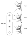
- . Les figures 3a, 3b et 3c illustrent respectivement en vue de face et en vue de dessus, de dessous l'embase filetée.
- . La figure 4 montre le bouclier venant s'encastrer dans l'embase;
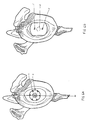
- e Les figures 5a et 5b sont respectivement une vue de face et de dessus du dispositif glénoïde, objet de l'invention.
- e Les figures 6a et 6b représentent respectivement l'emplacement de l'embase et du bouclier dans la cavité glénoïde .
- . Figure 1 shows a front view of the cushion.
- . Figures 2a and 2b show respectively in front view in section and in top view of the shield.
- . Figures 2c and 2d show this same shield in front view with studs of different shapes.
- . Figures 3a, 3b and 3c respectively illustrate a front view and a top view, from below the threaded base.
- . Figure 4 shows the shield coming to be embedded in the base;
- e Figures 5a and 5b are respectively a front view and from above of the glenoid device, object of the invention.
- e Figures 6a and 6b respectively show the location of the base and the shield in the glenoid cavity.
La figure 3a représente une embase filetée et perforée (0) comportant une platine circulaire (1) percée (2) et une vis à gros filet (3). Le vissage de l'embase doit être effectué "à fond" pour que la platine percée se retrouve au contact de l'os comme le montre la figure 6a. Cette mise en place s'effectue à l'aide de la broche-guide et d'un ancillaire simple (fraise et taraud) et adapté à la préhension des éléments prothétiques. La broche est plantée dans le centre de la cavité glénoïde de l'omoplate. Cette broche de 3 à 6 cm servira de guide permanent j'usqu'à la fin de l'ancrage de l'embase filetée dans l'os. Implantée à une de ses extrémités dans l'os et à l'autre dans l'embase perforée (0), elle permet une précision optimale de direction d'insertion. Une fois implantée, l'embase se retrouve dans une position aléatoire, et il suffit d'effectuer une rotation minime dans le sens du serrage pour trouver un couple de trous, diamétralement opposés se confondant avec l'axe vertical (AV).Figure 3a shows a threaded and perforated base (0) comprising a circular plate (1) pierced (2) and a coarse thread screw (3). The screwing of the base must be done "fully" so that the pierced plate is in contact with the bone as shown in Figure 6a. This installation is carried out using the guide pin and a simple ancillary (strawberry and tap) and suitable for gripping prosthetic elements. The pin is planted in the center of the glenoid cavity of the scapula. This 3 to 6 cm pin will serve as a permanent guide until the end of the anchoring of the threaded base in the bone. Implanted at one of its ends in the bone and at the other in the perforated base (0), it allows optimal precision in the direction of insertion. Once implanted, the base is in a random position, and it suffices to make a minimal rotation in the direction of tightening to find a couple of holes, diametrically opposite merging with the vertical axis (AV).
Le bouclier et l'embase filetée s'assemblent par un six pans comme le montre la figure 4, ce qui permet de les positionner l'un par rapport à l'autre, les plots du bouclier (5) venant s'encastrer dans l'os préalablement guidé ou rendu complètement solidaire de l'embase filetée par déformation des trous de passage apparents sur celle-ci (7).The shield and the threaded base are assembled by a hexagon as shown in Figure 4, which allows to position them relative to each other, the shield studs (5) coming to be embedded in the 'bone previously guided or made completely integral with the threaded base by deformation of the visible through holes thereon (7).
Le bouclier représenté par les figures 2a et 2b constitué d'un six pans mâle (6) possède en sa jonction une partie cannelée droite (7) venant s'encastrer pendant l'impaction dans la bague de verrouillage de l'embase filetée (7'). Le couple bague/cannelure permet ainsi un arrêt primaire de translation et de rotation.The shield represented by FIGS. 2a and 2b consisting of a male hexagon (6) has at its junction a straight grooved part (7) which is fitted during the impact in the locking ring of the threaded base (7 '). The ring / spline pair thus allows a primary stop of translation and rotation.
La rotation du bouclier dans l'embase filetée, le dévissage de l'ensemble et les micro-mouvements sont supprimés par la présence du six pans et des plots.The rotation of the shield in the threaded base, the unscrewing of the assembly and the micro-movements are eliminated by the presence of the hexagon and the studs.
Tous les degrés de liberté étant supprimés, la glène se trouve donc immobilisée, la prothèse humérale vient se positionner dans le coussin (8) .All the degrees of freedom being removed, the glenoid is therefore immobilized, the humeral prosthesis is positioned in the cushion (8).
Claims (11)
Applications Claiming Priority (2)
| Application Number | Priority Date | Filing Date | Title |
|---|---|---|---|
| FR9209343A FR2694186B1 (en) | 1992-07-29 | 1992-07-29 | Screwed glenoid prosthesis and placement method. |
| FR9209343 | 1992-07-29 |
Publications (1)
| Publication Number | Publication Date |
|---|---|
| EP0581667A1 true EP0581667A1 (en) | 1994-02-02 |
Family
ID=9432376
Family Applications (1)
| Application Number | Title | Priority Date | Filing Date |
|---|---|---|---|
| EP93401939A Ceased EP0581667A1 (en) | 1992-07-29 | 1993-07-27 | Screw-in glene prosthesis |
Country Status (2)
| Country | Link |
|---|---|
| EP (1) | EP0581667A1 (en) |
| FR (1) | FR2694186B1 (en) |
Cited By (20)
| Publication number | Priority date | Publication date | Assignee | Title |
|---|---|---|---|---|
| EP1013246A1 (en) * | 1998-12-22 | 2000-06-28 | Sulzer Orthopedics Ltd. | Glenoid prosthesis and modular system with glenoid prostheses |
| FR2802799A1 (en) * | 1999-12-23 | 2001-06-29 | Depuy France | Shoulder prosthesis assembly has glenoid sphere made with guide to facilitate correct assembly |
| EP1136046A2 (en) * | 2000-03-17 | 2001-09-26 | Depuy Orthopaedics, Inc. | Cementless glenoid component |
| WO2008000928A2 (en) * | 2006-06-28 | 2008-01-03 | Trois S Ortho | Shoulder prosthesis and set of instruments for the implantation thereof |
| FR2940607A1 (en) * | 2008-12-29 | 2010-07-02 | Didier Capon | GLENOIDAL IMPLANT COMPRISING A CUP FOR COOPERATING WITH A PROTHETIC HUMERAL HEAD |
| US7918892B2 (en) | 1998-03-17 | 2011-04-05 | Acumed Llc | Shoulder prosthesis |
| WO2011044879A1 (en) * | 2009-10-12 | 2011-04-21 | Aap Implantate Ag | Modular system for anchoring and positioning components of implants |
| US8231683B2 (en) | 2009-12-08 | 2012-07-31 | Depuy Products, Inc. | Shoulder prosthesis assembly having glenoid rim replacement structure |
| EP2481376A1 (en) | 2011-02-01 | 2012-08-01 | Tornier | Glenoidal implant for shoulder prosthesis and surgical kit |
| US8241365B2 (en) | 2008-12-23 | 2012-08-14 | Depuy Products, Inc. | Shoulder prosthesis with vault-filling structure having bone-sparing configuration |
| US8961611B2 (en) | 2010-11-24 | 2015-02-24 | DePuy Synthes Products, LLC | Modular glenoid prosthesis |
| US9149362B2 (en) | 2004-09-27 | 2015-10-06 | DePuy Synthes Products, Inc. | Instrument for preparing an implant support surface and associated method |
| US9301848B2 (en) | 2010-11-24 | 2016-04-05 | DePuy Synthes Products, Inc. | Modular glenoid prosthesis |
| US9517139B2 (en) | 2010-01-15 | 2016-12-13 | DePuy Synthes Products, Inc. | Acromion spacer |
| US9629725B2 (en) | 2014-01-03 | 2017-04-25 | Tornier, Inc. | Reverse shoulder systems and methods |
| US10722374B2 (en) | 2015-05-05 | 2020-07-28 | Tornier, Inc. | Convertible glenoid implant |
| EP3838230A1 (en) * | 2019-12-16 | 2021-06-23 | Waldemar Link GmbH & Co. KG | Anchoring member for a joint replacement |
| US11160661B2 (en) | 2009-12-14 | 2021-11-02 | Tornier Sas | Shoulder prosthesis glenoid component |
| US11564802B2 (en) | 2017-10-16 | 2023-01-31 | Imascap Sas | Shoulder implants and assembly |
| US11779471B2 (en) | 2019-08-09 | 2023-10-10 | Howmedica Osteonics Corp. | Apparatuses and methods for implanting glenoid prostheses |
Citations (4)
| Publication number | Priority date | Publication date | Assignee | Title |
|---|---|---|---|---|
| EP0091315A1 (en) * | 1982-04-07 | 1983-10-12 | National Research Development Corporation | Endoprosthetic bone joint devices |
| FR2578739A1 (en) * | 1985-03-12 | 1986-09-19 | Rambert Andre | Humeral prosthesis |
| FR2579454A1 (en) * | 1985-03-28 | 1986-10-03 | Rambert Andre | Glenohumeral prosthesis |
| FR2652498A1 (en) * | 1989-10-04 | 1991-04-05 | Medinov | Modular assembly for a shoulder prosthesis |
-
1992
- 1992-07-29 FR FR9209343A patent/FR2694186B1/en not_active Expired - Fee Related
-
1993
- 1993-07-27 EP EP93401939A patent/EP0581667A1/en not_active Ceased
Patent Citations (4)
| Publication number | Priority date | Publication date | Assignee | Title |
|---|---|---|---|---|
| EP0091315A1 (en) * | 1982-04-07 | 1983-10-12 | National Research Development Corporation | Endoprosthetic bone joint devices |
| FR2578739A1 (en) * | 1985-03-12 | 1986-09-19 | Rambert Andre | Humeral prosthesis |
| FR2579454A1 (en) * | 1985-03-28 | 1986-10-03 | Rambert Andre | Glenohumeral prosthesis |
| FR2652498A1 (en) * | 1989-10-04 | 1991-04-05 | Medinov | Modular assembly for a shoulder prosthesis |
Cited By (43)
| Publication number | Priority date | Publication date | Assignee | Title |
|---|---|---|---|---|
| US7918892B2 (en) | 1998-03-17 | 2011-04-05 | Acumed Llc | Shoulder prosthesis |
| US6406495B1 (en) | 1998-12-22 | 2002-06-18 | Sulzer Orthopedics Ltd. | Glenoid prosthesis and a modular system with glenoid prostheses |
| EP1013246A1 (en) * | 1998-12-22 | 2000-06-28 | Sulzer Orthopedics Ltd. | Glenoid prosthesis and modular system with glenoid prostheses |
| GB2375052A (en) * | 1999-12-23 | 2002-11-06 | Depuy France | Shoulder prosthesis assembly |
| WO2001047442A1 (en) * | 1999-12-23 | 2001-07-05 | Depuy France | Shoulder prosthesis assembly |
| US8361157B2 (en) | 1999-12-23 | 2013-01-29 | Depuy France | Method of implanting a shoulder prosthesis assembly |
| GB2375052B (en) * | 1999-12-23 | 2004-03-24 | Depuy France | A shoulder prosthesis assembly |
| US6953478B2 (en) | 1999-12-23 | 2005-10-11 | Depuy France | Shoulder prosthesis assembly |
| FR2802799A1 (en) * | 1999-12-23 | 2001-06-29 | Depuy France | Shoulder prosthesis assembly has glenoid sphere made with guide to facilitate correct assembly |
| US7611539B2 (en) | 1999-12-23 | 2009-11-03 | Depuy France | Shoulder prosthesis assembly |
| EP1136046A2 (en) * | 2000-03-17 | 2001-09-26 | Depuy Orthopaedics, Inc. | Cementless glenoid component |
| US6911047B2 (en) | 2000-03-17 | 2005-06-28 | Depuy Orthopaedics, Inc. | Apparatus and method for securing a cementless glenoid component to a glenoid surface of a scapula |
| AU782185B2 (en) * | 2000-03-17 | 2005-07-07 | Depuy Orthopaedics, Inc. | Apparatus and method for securing a cementless glenoid component to a glenoid surface of a scapula |
| US7160328B2 (en) | 2000-03-17 | 2007-01-09 | Deputy Products, Inc. | Method for securing a glenoid component to a scapula |
| EP1136046A3 (en) * | 2000-03-17 | 2001-10-04 | Depuy Orthopaedics, Inc. | Cementless glenoid component |
| US9149362B2 (en) | 2004-09-27 | 2015-10-06 | DePuy Synthes Products, Inc. | Instrument for preparing an implant support surface and associated method |
| WO2008000928A3 (en) * | 2006-06-28 | 2008-02-07 | Trois S Ortho | Shoulder prosthesis and set of instruments for the implantation thereof |
| FR2902993A1 (en) * | 2006-06-28 | 2008-01-04 | Trois S Ortho Sa | SHOULDER PROSTHESIS AND INSTRUMENT SET FOR THE IMPLANTATION OF THIS PROSTHESIS |
| WO2008000928A2 (en) * | 2006-06-28 | 2008-01-03 | Trois S Ortho | Shoulder prosthesis and set of instruments for the implantation thereof |
| US8241365B2 (en) | 2008-12-23 | 2012-08-14 | Depuy Products, Inc. | Shoulder prosthesis with vault-filling structure having bone-sparing configuration |
| WO2010076534A1 (en) * | 2008-12-29 | 2010-07-08 | Aston Medical Developments Ltd | Glenoid implant |
| FR2940607A1 (en) * | 2008-12-29 | 2010-07-02 | Didier Capon | GLENOIDAL IMPLANT COMPRISING A CUP FOR COOPERATING WITH A PROTHETIC HUMERAL HEAD |
| US8721726B2 (en) | 2008-12-29 | 2014-05-13 | Aston Medical Developments Limited | Glenoid implant |
| WO2011044879A1 (en) * | 2009-10-12 | 2011-04-21 | Aap Implantate Ag | Modular system for anchoring and positioning components of implants |
| US8231683B2 (en) | 2009-12-08 | 2012-07-31 | Depuy Products, Inc. | Shoulder prosthesis assembly having glenoid rim replacement structure |
| US11160661B2 (en) | 2009-12-14 | 2021-11-02 | Tornier Sas | Shoulder prosthesis glenoid component |
| US9517139B2 (en) | 2010-01-15 | 2016-12-13 | DePuy Synthes Products, Inc. | Acromion spacer |
| US8961611B2 (en) | 2010-11-24 | 2015-02-24 | DePuy Synthes Products, LLC | Modular glenoid prosthesis |
| US9301848B2 (en) | 2010-11-24 | 2016-04-05 | DePuy Synthes Products, Inc. | Modular glenoid prosthesis |
| US10918492B2 (en) | 2011-02-01 | 2021-02-16 | Tornier Sas | Glenoid implant for a shoulder prosthesis, and surgical kit |
| EP2481376A1 (en) | 2011-02-01 | 2012-08-01 | Tornier | Glenoidal implant for shoulder prosthesis and surgical kit |
| US9498345B2 (en) | 2011-02-01 | 2016-11-22 | Tornier Sas | Glenoid implant for a shoulder prosthesis, and surgical kit |
| US11877933B2 (en) | 2011-02-01 | 2024-01-23 | Tornier Sas | Glenoid implant for a shoulder prosthesis, and surgical kit |
| US10064734B2 (en) | 2011-02-01 | 2018-09-04 | Tornier Sas | Glenoid implant for a shoulder prosthesis, and surgical kit |
| FR2971144A1 (en) * | 2011-02-08 | 2012-08-10 | Tornier Sa | GLENOIDAL IMPLANT FOR SHOULDER PROSTHESIS AND SURGICAL KIT |
| US10357373B2 (en) | 2014-01-03 | 2019-07-23 | Tornier, Inc. | Reverse shoulder systems and methods |
| US11103357B2 (en) | 2014-01-03 | 2021-08-31 | Howmedica Osteonics Corp. | Reverse shoulder systems and methods |
| US9629725B2 (en) | 2014-01-03 | 2017-04-25 | Tornier, Inc. | Reverse shoulder systems and methods |
| US10722374B2 (en) | 2015-05-05 | 2020-07-28 | Tornier, Inc. | Convertible glenoid implant |
| US11564802B2 (en) | 2017-10-16 | 2023-01-31 | Imascap Sas | Shoulder implants and assembly |
| US11779471B2 (en) | 2019-08-09 | 2023-10-10 | Howmedica Osteonics Corp. | Apparatuses and methods for implanting glenoid prostheses |
| EP3838230A1 (en) * | 2019-12-16 | 2021-06-23 | Waldemar Link GmbH & Co. KG | Anchoring member for a joint replacement |
| WO2021122570A1 (en) * | 2019-12-16 | 2021-06-24 | Waldemar Link Gmbh & Co. Kg | Anchoring member for a joint replacement |
Also Published As
| Publication number | Publication date |
|---|---|
| FR2694186A1 (en) | 1994-02-04 |
| FR2694186B1 (en) | 1994-09-16 |
Similar Documents
| Publication | Publication Date | Title |
|---|---|---|
| EP0581667A1 (en) | Screw-in glene prosthesis | |
| EP1510190B1 (en) | Glenoid component of a shoulder prosthesis and total shoulder prosthesis comprising such a component | |
| EP0549480B1 (en) | Modular humeral prosthesis | |
| EP1611872B1 (en) | Shoulder or hip prosthesis | |
| CA2224478C (en) | Cotyloidal implant fixed without cement | |
| EP2032082B1 (en) | Shoulder prosthesis and set of instruments for the implantation thereof | |
| EP0815810A1 (en) | Shoulder prosthesis and set of humeral shafts for such a prosthesis | |
| WO2003013397A2 (en) | Modular acetabular cup, and anchoring screw for fixing a prosthetic implant such as said acetabular cup | |
| EP0038897B1 (en) | Non cemented intramedullary prosthesis for a hip joint | |
| FR2718014A1 (en) | Anchor screw assembly for joint prosthesis cup implant | |
| FR2579454A1 (en) | Glenohumeral prosthesis | |
| EP0797964A1 (en) | Assembly of elements for the formation of a total hip prosthesis | |
| EP0974316B1 (en) | Acetabular cup for hip prosthesis | |
| FR2651995A1 (en) | Ring for acetabular implant | |
| EP1670395A1 (en) | Humeral insert for an inverted shoulder prosthesis | |
| EP1520561B1 (en) | Scapular glenoid cavity prosthesis | |
| FR2650174A1 (en) | Artificial acetabulum for hip prostheses and system for putting it into position | |
| FR2960418A1 (en) | Glenoid assembly for shoulder prosthesis, has base plate provided with part for receiving anchoring rod and articulation element, where base plate is provided with another part with fixation arrangements in coracoid process | |
| FR2738739A1 (en) | Single-cotylar sliding knee joint replacement prosthesis | |
| FR2758255A1 (en) | Repeat cotyloid implant for hip replacement | |
| FR2768046A1 (en) | COTYLE WITH PLUGS | |
| FR2693367A1 (en) | Femoral rod penetrating whole length of bone - has series of recesses both perpendicular and parallel to longitudinal axis preventing movement within bone | |
| EP0864304B1 (en) | Ankle prosthesis | |
| FR2815846A1 (en) | Device for anterior vertebral arthrodesis comprises cage inserted between two vertebrae and connector for linking vertebrae which is screwed on to top of cage | |
| FR2799115A1 (en) | Modular shank for hip prosthesis comprises medullary pin with cylindrical surface for thrust member, stops and support |
Legal Events
| Date | Code | Title | Description |
|---|---|---|---|
| PUAI | Public reference made under article 153(3) epc to a published international application that has entered the european phase |
Free format text: ORIGINAL CODE: 0009012 |
|
| 17P | Request for examination filed |
Effective date: 19930802 |
|
| AK | Designated contracting states |
Kind code of ref document: A1 Designated state(s): AT BE CH DE DK ES GB GR IT LI LU NL PT SE |
|
| GRAG | Despatch of communication of intention to grant |
Free format text: ORIGINAL CODE: EPIDOS AGRA |
|
| 17Q | First examination report despatched |
Effective date: 19960412 |
|
| STAA | Information on the status of an ep patent application or granted ep patent |
Free format text: STATUS: THE APPLICATION HAS BEEN REFUSED |
|
| 18R | Application refused |
Effective date: 19961006 |