EP0581548A1 - Method for providing an extension on an end of an article having internal passageways - Google Patents
Method for providing an extension on an end of an article having internal passageways Download PDFInfo
- Publication number
- EP0581548A1 EP0581548A1 EP19930305850 EP93305850A EP0581548A1 EP 0581548 A1 EP0581548 A1 EP 0581548A1 EP 19930305850 EP19930305850 EP 19930305850 EP 93305850 A EP93305850 A EP 93305850A EP 0581548 A1 EP0581548 A1 EP 0581548A1
- Authority
- EP
- European Patent Office
- Prior art keywords
- article
- extension
- molten material
- die
- airfoil
- Prior art date
- Legal status (The legal status is an assumption and is not a legal conclusion. Google has not performed a legal analysis and makes no representation as to the accuracy of the status listed.)
- Withdrawn
Links
Images


Classifications
-
- F—MECHANICAL ENGINEERING; LIGHTING; HEATING; WEAPONS; BLASTING
- F01—MACHINES OR ENGINES IN GENERAL; ENGINE PLANTS IN GENERAL; STEAM ENGINES
- F01D—NON-POSITIVE DISPLACEMENT MACHINES OR ENGINES, e.g. STEAM TURBINES
- F01D5/00—Blades; Blade-carrying members; Heating, heat-insulating, cooling or antivibration means on the blades or the members
- F01D5/005—Repairing methods or devices
-
- B—PERFORMING OPERATIONS; TRANSPORTING
- B22—CASTING; POWDER METALLURGY
- B22D—CASTING OF METALS; CASTING OF OTHER SUBSTANCES BY THE SAME PROCESSES OR DEVICES
- B22D27/00—Treating the metal in the mould while it is molten or ductile ; Pressure or vacuum casting
- B22D27/04—Influencing the temperature of the metal, e.g. by heating or cooling the mould
- B22D27/045—Directionally solidified castings
-
- C—CHEMISTRY; METALLURGY
- C30—CRYSTAL GROWTH
- C30B—SINGLE-CRYSTAL GROWTH; UNIDIRECTIONAL SOLIDIFICATION OF EUTECTIC MATERIAL OR UNIDIRECTIONAL DEMIXING OF EUTECTOID MATERIAL; REFINING BY ZONE-MELTING OF MATERIAL; PRODUCTION OF A HOMOGENEOUS POLYCRYSTALLINE MATERIAL WITH DEFINED STRUCTURE; SINGLE CRYSTALS OR HOMOGENEOUS POLYCRYSTALLINE MATERIAL WITH DEFINED STRUCTURE; AFTER-TREATMENT OF SINGLE CRYSTALS OR A HOMOGENEOUS POLYCRYSTALLINE MATERIAL WITH DEFINED STRUCTURE; APPARATUS THEREFOR
- C30B11/00—Single-crystal growth by normal freezing or freezing under temperature gradient, e.g. Bridgman-Stockbarger method
- C30B11/002—Crucibles or containers for supporting the melt
-
- C—CHEMISTRY; METALLURGY
- C30—CRYSTAL GROWTH
- C30B—SINGLE-CRYSTAL GROWTH; UNIDIRECTIONAL SOLIDIFICATION OF EUTECTIC MATERIAL OR UNIDIRECTIONAL DEMIXING OF EUTECTOID MATERIAL; REFINING BY ZONE-MELTING OF MATERIAL; PRODUCTION OF A HOMOGENEOUS POLYCRYSTALLINE MATERIAL WITH DEFINED STRUCTURE; SINGLE CRYSTALS OR HOMOGENEOUS POLYCRYSTALLINE MATERIAL WITH DEFINED STRUCTURE; AFTER-TREATMENT OF SINGLE CRYSTALS OR A HOMOGENEOUS POLYCRYSTALLINE MATERIAL WITH DEFINED STRUCTURE; APPARATUS THEREFOR
- C30B29/00—Single crystals or homogeneous polycrystalline material with defined structure characterised by the material or by their shape
- C30B29/10—Inorganic compounds or compositions
- C30B29/52—Alloys
-
- Y—GENERAL TAGGING OF NEW TECHNOLOGICAL DEVELOPMENTS; GENERAL TAGGING OF CROSS-SECTIONAL TECHNOLOGIES SPANNING OVER SEVERAL SECTIONS OF THE IPC; TECHNICAL SUBJECTS COVERED BY FORMER USPC CROSS-REFERENCE ART COLLECTIONS [XRACs] AND DIGESTS
- Y10—TECHNICAL SUBJECTS COVERED BY FORMER USPC
- Y10T—TECHNICAL SUBJECTS COVERED BY FORMER US CLASSIFICATION
- Y10T29/00—Metal working
- Y10T29/49—Method of mechanical manufacture
- Y10T29/49316—Impeller making
- Y10T29/49318—Repairing or disassembling
Definitions
- This invention relates to growing an extension on an end of an article having internal passageways and having a directionally oriented microstructure, and, more particularly, to such a method in which the end is used as a growth seed for the extension and article extended thereby.
- the reported technology for growing directionally oriented structures from a molten bath of a selected material has evolved from simple shapes and members to complex shaped articles.
- a portion of such technology includes the generation in a complex shaped mold of directionally solidified alloy articles for use in the hot sections of gas turbine engines.
- the published literature well known to those skilled in such art has many examples of articles such as turbine blades and vanes provided in such a manner.
- an article for example a turbomachinery or gas turbine engine blading member
- an environment of airborne particles and particularly in the strenuous high temperature oxidizing and/or corrosive conditions experienced in the turbine section of a gas turbine engine oxidation, hot corrosion, erosion, wear, low-cycle fatigue cracking and other damage can occur to such an article. Because the manufacture of such article is expensive, it is desirable economically to repair rather than to replace the article.
- an article such as a blading member can be manufactured as a single crystal or with a directionally solidified microstructure of elongated grains.
- the combination of casting mold technology and casting procedures enables such manufacture.
- the characteristic crystal orientation in nickel-base superalloys frequently used for blading members is that the ⁇ 001> crystallographic direction lies substantially parallel to the growth direction; designers of such blading members can utilize that characteristic crystal orientation to minimize the elastic modulus, and therefore reduce the likelihood of mechanical failure due to a mechanism such as thermal fatigue, along a specified direction relative to the configuration of an article such as a blading member.
- the present invention in one form, describes a method for providing an extension on an end of an article having internal passageways and having a directionally oriented microstructure, from a molten material.
- the extension is grown using the end of the article as a directionally oriented microstructure growth seed for the molten material which is compatible with the article-seed structure.
- the extension is grown by providing a shaping member, for example, a die having a die opening, communicating with the molten material. Fluid pressure applied to the molten material forces it into the die opening where it is contacted by the article-seed for a time sufficient for the seed to interact with the molten material, for example, melting back a portion of the seed or enabling interdiffusion to occur.
- the article end acting as the growth seed, is withdrawn through the die opening at a rate which allows the molten material to directionally solidify on the growth seed as an extension of and integral with the article end. Also, it has a directionally oriented microstructure compatible with the article's directionally oriented microstructure.
- the die in another form, includes a hollow die extension which is in communication with the molten material. The article end is held in the die extension for contact with the molten material forced therein.
- the present invention provides an article comprising a body portion having internal passages or passageways and having a directionally oriented body or first crystal structure and a metallurgical structure and an extension integral with an end of the body portion through the use of a sacrificial addition secured to the end of the article prior to forming the extension.
- the extension has a directionally oriented crystal structure compatible with and extending continuous with the body portion crystal structure.
- the extension has a metallurgical structure compatible with and metallurgically distinguishable from the body's metallurgical structure.
- fluid pressure such as an inert gas or air
- a molten material such as a metal
- U.S. 3,302,252-Woodburn, Jr. patented February 7, 1967, relating to continuous casting of an article upwardly through a pouring tube into a cooled mold. The cast article is continuously withdrawn from the mold.
- EFG Electronic-defined, Film-fed Growth
- no external pressure is applied to a liquid material, but capillary action within a narrow forming tube or die is relied upon to draw the liquid material upwardly for solidification.
- a seed crystal is introduced into the liquid to initiate crystal growth.
- Typical patents which disclose features of this kind of process include U.S. 3,471,266-La Belle, Jr., patented October 7, 1969; U.S. 4,120,742-Asano et al., patented October 17, 1978; and U.S. 4,937,053-Harvey, patented June 26, 1990.
- seed crystals having selected crystal orientations have been used. They constitute starter means for solidification of an article having the selected crystal orientation.
- the method of the present invention provides a new combination of steps which casts or grows an extension directly on an end of an existing article to enable repair.
- the extension is provided with a crystal microstructure including orientation, matched with and continuous with that of the article.
- the extension has a metallurgical structure generally distinguishable from the metallurgical structure of the article end or body, from which the extension is grown.
- crystal structure is intended to mean the overall crystal form such as a single crystal, multiple elongated grains, etc. and the directional orientations thereof.
- metallurgical structure herein is intended to include such characteristics as overall chemical or alloy composition, and the size, shape, spacing and composition of precipitates, phases, inclusions, dendrites, etc. within the crystal structure.
- Ni-base superalloys generally include gamma prime precipitates, spaced dendrite arms and various other distinguishable phases.
- the crystal structure and metallurgical structure can be determined and identified by a variety of known and widely used techniques including chemical or spectrographic analysis and various x-ray and photomicrographic methods.
- microstructure herein includes the terms crystal structure and metallurgical structure.
- This method eliminates the need to provide a separate member as an article extension, to match the extension member crystal orientation with the article to be repaired, and then to bond the extension in the proper orientation to a portion of the article as shown in the above identified Patents 3,967,355 and 4,033,792.
- the method of this invention accomplishes all such steps in one operation, providing the extension integral and oriented with the article.
- the present invention is particularly useful in providing an extension on an article having a hollow interior and openings or passages communicating through an end of the article with the hollow interior.
- One form of the method of the present invention allows use of a sacrificial addition on an end of the article to be repaired to minimize interaction, such as melt back, of the article end with a molten material from which the article extension is grown. Furthermore, because the damaged article end in the present invention interacts directly with the molten material, such as in melt back, the need to pretreat or pre- shape or remove substantial material from the end can be substantially reduced or eliminated
- Asealed molybdenum canister 10 in this example of circular cross section, is provided with a resistance heater 12 of molybdenum. Within canister 10 is an alumina melt crucible 14. Through the top of canister 10 is a shaping member or die assembly shown generally at 16, in this embodiment including a shaping die 18 and a die extension 20. The die and the extension each have an inner wall, 22 and 24, respectively, defining hollow interiors thereof and die and die extension or shaping openings for receiving a molten material 26 from melt crucible 14.
- the die and die extension are made of alumina, commonly used in the high temperature casting art, and have cross sectional shapes matched with, but not necessarily identical to, the cross sectional shape of the article to be treated.
- the die extension 20 is typically made from either commercially available high-purity polycrystalline aluminum oxide (alumina) tubing or commercially available single crystal alumina (sapphire) tubing available from Saphikon Inc., Milford NH.
- the shaping die 18 is typically made from commercially available high purity low shrinkage short-fiber alumina paper sheet material such as Type 99W alumina paper, available from Zircar Products, Florida NY.
- Alumina cement such as ZPI-306 alumina cement available from Zircar Products, Florida NYwas used to cement lapped joints and highly deformed areas such as corners and bends in the alumina sheet material.
- the alumina cement is a mixture of short alumina fibers and small alumina particles with a small fraction of an unspecified organo- aluminum compound (probably aluminum diacetate orsubacetate) which serves as a binder in the unfired state.
- a high-purity castable alumina ceramic such as RTC-60 castable ceramic, available from Cotronics Corp., Brooklyn NY was used to provide a curved bottom surface to the melt pool in the shaping die 18.
- Airfoil die tops were made by forming and cementing the outer wall from alumina paper sheet in the appropriate shape, and then casting either a polycrystalline or a single crystal sapphire tube in place in the bottom with the castable alumina ceramic material.
- the die then comprised a die extension tube 20 feeding a shallow, approximately 0.6 inch deep, resevoir of the desired shaping die 18 shape.
- Fabrication procedures for die assemblies 16 using the castable ceramic consisted of overnight curing in a plastic bag to prevent non-uniform drying, a two-hour bakeout at approximately 110 degrees Centigrade (230°F), and a one- hour firing at 1000 degrees Centigrade (1832°F) to fully cure the ceramic.
- Surrounding die assembly 16 is a molybdenum resistance heater 28 to assist in control of the condition of the molten material 26 as it moves and solidifies within the hollow interior of die 18.
- a fluid pressure inlet tube 32 connected to a source of fluid pressure (not shown), such as argon, is disposed through a wall of the canister.
- a pressure gage 34 Sensing the pressure within the canister interior is a pressure gage 34, which can provide pressure data to a pressure control (not shown) for the source of fluid pressure, to maintain pressure at a desired, preselected level, or schedule of levels, within canister 10.
- Temperature sensing within canister interior 30 employs a thermocouple 36. Through a furnace temperature control 38, electric power to resistance heaters 12 and 28 is controlled and scheduled as desired.
- FIG. 2 The partially sectional, fragmentary view of Figure 2 is taken along line 2-2 of Figure 1.
- This figure in which the meaning of the reference numerals coincide with those of Figure 1, shows the shaping die 18, the die extension 20 and the die resistance heater 28.
- Each of these elements has an airfoil shaped cross section in Figure 2, which corresponds with the shape of airfoil article 40, in Figure 1.
- FIG. 2 shows the shaping die 18, the die extension 20 and the die resistance heater 28.
- Each of these elements has an airfoil shaped cross section in Figure 2, which corresponds with the shape of airfoil article 40, in Figure 1.
- FIG 1 An extension is being grown on the airfoil article 40 at solidification interface 42 in Figure 1.
- any shapes or assemblies of shapes can be used for such members, depending on the shape of the article being extended and the desired shape of the extension.
- a gas turbine engine turbine blade of the general type shown diagrammatically in Figure 3, was used.
- Such a blade included a base shown generally at 44, an airfoil shown generally at 46 and a blade tip 48.
- the blade had a hoi [Tui] iow interior for air cooling with cooling holes or passages such as 50 communicating with the hollow, generally labyrinthine, interior. Because such a blade had a directionally solidified microstructure, including a crystal structure as elongated multiple grains, repair of damage to tip 48 is difficult if such microstructure is to be continued into the repair.
- the present invention enables growth on the blade tip of an extension having a microstructure of crystal structure and metallurgical structure grown from and compatible with the parent blade tip.
- the material from which such blade was cast was a nickel base superalloy having a nominal composition, in weight percent, of 6.15% Al, 6.35% Ta, 4.9% W, 2.8% Re, 12% Co, 6.8% Cr, 1.5% Hf, with the balance Ni, selected minor alloy additions and incidental impurities.
- the microstructure of such cast blade was directionally oriented multiple elongated grains.
- nickel base superalloy was placed in melt crucible 14, Figure 1, within canister 10 which was then sealed.
- the nickel base superalloy in melt crucible 14 had a nominal composition, in weight percent, of 6.7% Al, 6.2% Ta, 2% Re, 10.5% Co, 16% Cr, 1.6% Hf, with the balance Ni, selected minor alloy additions and incidental impurities.
- the superalloy was melted by resistance heater 12 at a temperature in the range of about 2790 to 2905°F under a low-oxygen argon atmosphere.
- blade tip 48 to solidify in die 18 and grow an extension having the same directionally solidified multiple elongated grain crystal structure as airfoil blade tip 48.
- the extension was continuous and integral with the blade tip. Withdrawal and directional solidification was continued until an extension of about 0.4" was provided in the same configuration and crystal structure orientation as blade tip 48.
- die heater 28 was used to control the temperature in die assembly 16 and the position of solidification interface 42. Further control of the solidifying interface can be accomplished using a chill in that location, not shown, as is well known and widely used in the directional solidification casting art. Such a chill can provide as steep a thermal gradient as is desired for selected solidification and microstructure growth.
- the die assembly was made of alumina, the variation of melt depth across the airfoil shaped cross section of the die assembly was observed to be that as would be expected in a non-wetting system. This enabled positioning of the growth seed blade tip portion in the die so that contact with the entire tip, from leading to trailing edge, was accomplished.
- the composition of the blade tip alloy was different from that of the alloy of the extension grown on the tip from the melt.
- the two compositions were selected so that the crystal structure of the extension would grow integral with and continuous from that of the blade tip representing the body portion for the extension.
- This mode of growth is sometimes termed epitaxial growth.
- this is generally a necessary condition for compatibility between the alloy of the blade tip (or body portion) and that of the extension.
- Compatibility generally implies that neither alloy adversely affect the other, whether by contamination, liquid metal embrittlement, formation of brittle phases at the interface, or otherwise.
- Compatibility may also imply some limitation on discontinuities in mechanical and physical properties and metallurgical structure between the blade tip and the extension.
- compatibility must be measured by performance. If extensions of one alloy can be repeatably grown on articles of another alloy, if the article with an extension grown thereon is amenable to subsequent manufacturing operations, and if the finished article performs satisfactorily in service, then it must be concluded that the two alloys are compatible, exceptions to the preceding generalities notwithstanding. The same considerations apply to sacrificial additions. As used herein, the phrase "molten material compatible with " is taken to mean a material or alloy that meets the preceding standard for compatibility, present in its liquid form.
- the article generated from practice of this invention included a body portion, for example, the parent blade tip having internal passageways and having a first crystal structure in the above example, directionally oriented elongated multiple grains, and a first metallurgical structure based on the alloy composition of the body portion. Integral and continuous with the body portion was an extension having a second crystal structure as a continuation of and compatible with the first crystal structure of the body portion and having a second metallurgical structure matched and compatible with, but distinguishable from, the first metallurgical structure of the body.
- the interface portion between the body and the extension is different from that obtained by the prior art method of diffusion bonding together matched, separately generated, distinct members.
- the principal distinction between the present invention and the prior art lies at the interface.
- the extension is grown epitaxially by laying down one layer of atoms after another from the liquid material selected for the extension onto the surface of the body.
- the crystal structure is continuous across the interface.
- the process of the present invention further allows the secondary grain orientation to be grown, unlike the prior art interface bonding techniques for which such secondary grain orientation is difficult to match in the transverse direction.
- the epitaxial grown region or repaired area thus matches the original metallurgical grain structure or orientation of the article not only in the primary, but also the secondary, direction.
- the advantage over current repair methods which have equiaxed grains at the interface and in the repaired area is significant in terms of mechanical and metallurgical properties since the metallurgical grain structure of the original article does not match the extension or repaired area by use of prior art methods.
- the airfoil 46 of Figure 3 includes an extension 56, Figure 4, from broken line 52 at which it was desired to provide a repair.
- extension 56 As seen in the fragmentary, diagrammatic view of Figure 4, using airfoil 46 as a growth seed results in extension 56 having a compatible microstructure, in this example including multiple elongated grains, as a continuation of and integral with that of the parent airfoil.
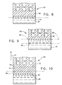
- FIG. 5 Another form of the tip portion of a gas turbine engine air cooled blade is shown in the fragmentary view of Figure 5 and the sectional view of Figure 6 taken along line 6-6 of Figure 5.
- this type of tip is referred to as a "squealer tip" because under certain operating conditions it can interfere with or rub on an opposing member to approach a zero clearance condition.
- peripheral rim 58, Figures 5 and 6, of airfoil 60 can be abraded or damaged. Even without such a rub condition, airborne particles and oxidation, over a period of operation, can abrade and contribute to the damage of rim 58.
- the method of the present invention can be used to repair such damage by providing an extension in the manner described in the above example.
- rim 58 when rim 58 is narrow or damage extends close to shelf 62, interaction of rim 58, such as melt back in melt 26 in Figure 1, should be limited and carefully controlled in order to avoid damage to shelf 62.
- One form of the method of the present invention provides use of a sacrificial addition carried by rim 58 at 64 in Figure 7.
- the edge or surface 66 of rim 58 in Figure 7 is represented to be eroded, damaged and in need of repair.
- Sacrificial addition 64 need not have the same microstructure as the blade tip, for example, elongated multiple grains or a single crystal. All that is required is that it be attached to rim 58 and be of a material which is compatible with that of melt 26.
- melt 26 is a nickel base superalloy
- addition 64 can be Ni, a Ni base alloy having elements which will not dilute or substantially change the composition of melt 26, an alloy of one of the alloying elements of melt 26, etc.
- Addition 64 can be applied by a variety of methods well known in the art, including flame spraying, electro-deposition, diffusion bonding of a preformed member, etc., provided that the passageways are unaffected. If the passageways are affected, additional operations may be required to assure communication with the article interior.
- the shape of addition 64 can be any convenient one: it can be shaped as an extension of rim 58 as shown in Figure 7, it can be a shim, sheet or foil carried by rim 58, etc.
- the melting away of addition 64 by melt 26 exposes at least the surface microstructure of rim 58 to melt 26 enabling such surface to act as a growth seed, according to this invention.
- Use of a sacrificial addition 64 facilitates the proper positioning of airfoil article 40 in Figure 1 so that when an article such as airfoil 60 in Figures 5, 6 and 7 is being repaired, the melt back line 68 in Figure 7 is located away from rather than at or in shelf 62. Without such sacrificial addition, it might be required, in order to achieve complete contact of and interaction with melt 26, to melt back rim 58 into shelf 62.
- Figures 8, 9 and 10 which are diagrammatically in section, show a sequence of the practice of the method of the present invention in a surrounding shaping die (not shown) as in Figure 1, in relation to repair of an article having a hollow interior.
- such interior can be the labyrinthine passages 70 in an air cooled turbine blade or vane.
- Figure 8 shows rim 58 in contact with and partially melted back by melt 26 from previous rim edge 66 shown in phantom. In Figure 9, melt back has continued further into rim 58 to melt back line 68, sufficient for the remaining portion of rim 58 to act as a growth seed for melt 26.
- airfoil 60 is moved upwardly, as shown by arrow 54 in Figure 10, while in contact with melt 26 until extension 56, delineated by broken line 72, is grown on rim 58 by solidification above melt line 68 which becomes solidification interface 42, as described above.
- additional holes can be drilled therein to allow air egress or external communication with the hollow interior, as desired.
- such holes can be generated by drilling with laser, electrochemical or electro discharge methods well known and widely used in the art of material removal.
- One evaluation of the present invention used an air cooled turbine blade of the type shown in Figures 5,6 and 7, and which had been exposed to gas turbine type operating conditions.
- the blade was manufactured from the same nickel base superalloy as in the previous example.
- This alloy includes in its composition AI and Hf, which when exposed to high temperature oxidizing conditions form stable surface oxides.
- Such alloying elements, and occasionally yttrium, are commonly used in nickel base superalloys from which turbine blades are manufactured. Therefore, the exposed surfaces of air cooling passages or holes, such as holes 74 in Figures 5, 6 and 7, were coated with surface oxides which were found not to interact with or melt in the molten material such as melt 26. Because such surfaces were oxides, they act as non-wetting molds.
- melt back was allowed to proceed into the blade material in which the holes were generated.
- melt 26 which had the same composition as the extension material of the previous example, and their integrity was maintained.
- pre-treatment to remove oxides, coatings, etc. such as mechanical or chemical surface treatment, can be used to facilitate article extension growth.
- the fluid pressure applied to the melt is selected to be adequate to move the melt into the shaping member but less than that required to force the melt into the oxide coated holes. Such pressure limit is a function of the size of the holes.
- the present invention relates to using an article or member having at least one internal passageway as a directionally oriented growth seed for providing on an end of the member a distinguishable extension having a microstructure matched with that of the member.
- Such an extension is provided from a molten material which is compatible or matched with the material of the growth seed so that the extension is integral with the member and has a microstructure continuous with that of the member.
- the composition of the member and of the molten material, and hence the extension grown therefrom need not be identical.
- Selection of the molten material for example to provide the extension with enhanced environmental resistance, is based on the tolerable degree of crystal structure mismatch between the member, acting as a growth seed, and the extension, grown from the molten material.
- the rate of movement of the article end, acting as the growth seed, from the molten material is a function at least of the fluid pressure applied, the temperature of the melt, the thermal gradient at the solidifying interface and the rate of solidification and growth of the extension.
Applications Claiming Priority (2)
| Application Number | Priority Date | Filing Date | Title |
|---|---|---|---|
| US07/922,303 US5291937A (en) | 1992-07-30 | 1992-07-30 | Method for providing an extension on an end of an article having internal passageways |
| US922303 | 1992-07-30 |
Publications (1)
| Publication Number | Publication Date |
|---|---|
| EP0581548A1 true EP0581548A1 (en) | 1994-02-02 |
Family
ID=25446860
Family Applications (1)
| Application Number | Title | Priority Date | Filing Date |
|---|---|---|---|
| EP19930305850 Withdrawn EP0581548A1 (en) | 1992-07-30 | 1993-07-23 | Method for providing an extension on an end of an article having internal passageways |
Country Status (5)
| Country | Link |
|---|---|
| US (1) | US5291937A (ja) |
| EP (1) | EP0581548A1 (ja) |
| JP (1) | JPH07110408B2 (ja) |
| CA (1) | CA2089286A1 (ja) |
| SG (1) | SG43014A1 (ja) |
Cited By (2)
| Publication number | Priority date | Publication date | Assignee | Title |
|---|---|---|---|---|
| EP0581547B1 (en) * | 1992-07-30 | 1998-02-18 | General Electric Company | Method for providing an extension on an end of an article and extended article |
| EP2846957B1 (en) * | 2012-05-11 | 2018-11-07 | Siemens Energy, Inc. | Repair of directionally solidified alloys |
Families Citing this family (14)
| Publication number | Priority date | Publication date | Assignee | Title |
|---|---|---|---|---|
| US5900170A (en) * | 1995-05-01 | 1999-05-04 | United Technologies Corporation | Containerless method of producing crack free metallic articles by energy beam deposition with reduced power density |
| US5914059A (en) * | 1995-05-01 | 1999-06-22 | United Technologies Corporation | Method of repairing metallic articles by energy beam deposition with reduced power density |
| US5778960A (en) * | 1995-10-02 | 1998-07-14 | General Electric Company | Method for providing an extension on an end of an article |
| US5904201A (en) * | 1996-01-18 | 1999-05-18 | General Electric Company | Solidification of an article extension from a melt using a ceramic mold |
| US5673745A (en) * | 1996-06-27 | 1997-10-07 | General Electric Company | Method for forming an article extension by melting of an alloy preform in a ceramic mold |
| US5676191A (en) * | 1996-06-27 | 1997-10-14 | General Electric Company | Solidification of an article extension from a melt using an integral mandrel and ceramic mold |
| US5743322A (en) * | 1996-06-27 | 1998-04-28 | General Electric Company | Method for forming an article extension by casting using a ceramic mold |
| US5673744A (en) * | 1996-06-27 | 1997-10-07 | General Electric Company | Method for forming an article extension by melting of a mandrel in a ceramic mold |
| US5732467A (en) * | 1996-11-14 | 1998-03-31 | General Electric Company | Method of repairing directionally solidified and single crystal alloy parts |
| US6932145B2 (en) * | 1998-11-20 | 2005-08-23 | Rolls-Royce Corporation | Method and apparatus for production of a cast component |
| US7418993B2 (en) * | 1998-11-20 | 2008-09-02 | Rolls-Royce Corporation | Method and apparatus for production of a cast component |
| AU2027000A (en) * | 1998-11-20 | 2000-09-21 | Allison Engine Company, Inc. | Method and apparatus for production of a cast component |
| US7575038B2 (en) | 2001-06-11 | 2009-08-18 | Howmet Research Corporation | Single crystal seed |
| JP4528995B2 (ja) * | 2007-08-02 | 2010-08-25 | 国立大学法人東北大学 | Siバルク多結晶インゴットの製造方法 |
Citations (4)
| Publication number | Priority date | Publication date | Assignee | Title |
|---|---|---|---|---|
| EP0092496A1 (en) * | 1982-03-01 | 1983-10-26 | United Technologies Corporation | Mold with starter and selector sections for directional solidification casting |
| DE2949446C2 (ja) * | 1978-12-13 | 1989-01-26 | United Technologies Corp., Hartford, Conn., Us | |
| EP0401187A2 (en) * | 1989-06-01 | 1990-12-05 | Abb Stal Ab | Method for reconstruction of blades and vanes in steam turbines at existing erosion damages |
| EP0493685A1 (de) * | 1990-12-13 | 1992-07-08 | SULZER- MTU CASTING TECHNOLOGY GmbH | Verfahren und Vorrichtung zur Reparatur von Triebwerksschaufeln |
Family Cites Families (3)
| Publication number | Priority date | Publication date | Assignee | Title |
|---|---|---|---|---|
| US3752221A (en) * | 1969-10-30 | 1973-08-14 | United Aircraft Corp | Mold apparatus for casting with downward unidirectional solidification |
| US4714101A (en) * | 1981-04-02 | 1987-12-22 | United Technologies Corporation | Method and apparatus for epitaxial solidification |
| US4637448A (en) * | 1984-08-27 | 1987-01-20 | Westinghouse Electric Corp. | Method for production of combustion turbine blade having a single crystal portion |
-
1992
- 1992-07-30 US US07/922,303 patent/US5291937A/en not_active Expired - Fee Related
-
1993
- 1993-02-11 CA CA002089286A patent/CA2089286A1/en not_active Abandoned
- 1993-07-19 JP JP5177151A patent/JPH07110408B2/ja not_active Expired - Fee Related
- 1993-07-23 EP EP19930305850 patent/EP0581548A1/en not_active Withdrawn
- 1993-07-23 SG SG1996002390A patent/SG43014A1/en unknown
Patent Citations (4)
| Publication number | Priority date | Publication date | Assignee | Title |
|---|---|---|---|---|
| DE2949446C2 (ja) * | 1978-12-13 | 1989-01-26 | United Technologies Corp., Hartford, Conn., Us | |
| EP0092496A1 (en) * | 1982-03-01 | 1983-10-26 | United Technologies Corporation | Mold with starter and selector sections for directional solidification casting |
| EP0401187A2 (en) * | 1989-06-01 | 1990-12-05 | Abb Stal Ab | Method for reconstruction of blades and vanes in steam turbines at existing erosion damages |
| EP0493685A1 (de) * | 1990-12-13 | 1992-07-08 | SULZER- MTU CASTING TECHNOLOGY GmbH | Verfahren und Vorrichtung zur Reparatur von Triebwerksschaufeln |
Cited By (3)
| Publication number | Priority date | Publication date | Assignee | Title |
|---|---|---|---|---|
| EP0581547B1 (en) * | 1992-07-30 | 1998-02-18 | General Electric Company | Method for providing an extension on an end of an article and extended article |
| EP2846957B1 (en) * | 2012-05-11 | 2018-11-07 | Siemens Energy, Inc. | Repair of directionally solidified alloys |
| US10415390B2 (en) | 2012-05-11 | 2019-09-17 | Siemens Energy, Inc. | Repair of directionally solidified alloys |
Also Published As
| Publication number | Publication date |
|---|---|
| SG43014A1 (en) | 1997-10-17 |
| CA2089286A1 (en) | 1994-01-31 |
| JPH07110408B2 (ja) | 1995-11-29 |
| US5291937A (en) | 1994-03-08 |
| JPH06182523A (ja) | 1994-07-05 |
Similar Documents
| Publication | Publication Date | Title |
|---|---|---|
| EP0581547B1 (en) | Method for providing an extension on an end of an article and extended article | |
| US5778960A (en) | Method for providing an extension on an end of an article | |
| US5291937A (en) | Method for providing an extension on an end of an article having internal passageways | |
| EP0815993B1 (en) | Method for forming an article extension by casting using a ceramic mold | |
| EP0815992B1 (en) | Method for forming an article extension by melting of an alloy preform in a ceramic mold | |
| EP1049561B1 (en) | Turbine components comprising thin skins bonded to superalloy substrates | |
| JP4659164B2 (ja) | 一方向凝固鋳造品並びにその製造方法 | |
| US6648596B1 (en) | Turbine blade or turbine vane made of a ceramic foam joined to a metallic nonfoam, and preparation thereof | |
| US3847203A (en) | Method of casting a directionally solidified article having a varied composition | |
| EP0475428B1 (en) | Gas turbine, gas turbine blade used therefor and manufacturing method for gas turbine blade | |
| EP2204475A2 (en) | Unidirectional-solidification process and castings formed thereby | |
| US20130022803A1 (en) | Unidirectionally-solidification process and castings formed thereby | |
| EP0815990B1 (en) | Solidification of an article extension from a melt using an integral mandrel and ceramic mold | |
| EP0785039B1 (en) | Solidification of an article extension from a melt using a ceramic mold | |
| EP0815991B1 (en) | Method for forming an article extension by melting of a mandrel in a ceramic mold | |
| US20230033669A1 (en) | Multiple materials and microstructures in cast alloys |
Legal Events
| Date | Code | Title | Description |
|---|---|---|---|
| PUAI | Public reference made under article 153(3) epc to a published international application that has entered the european phase |
Free format text: ORIGINAL CODE: 0009012 |
|
| AK | Designated contracting states |
Kind code of ref document: A1 Designated state(s): DE FR GB IT |
|
| RIN1 | Information on inventor provided before grant (corrected) |
Inventor name: ANDREWS, BRIAN MAC Inventor name: MCALLISTER, KEVIN GREGORY Inventor name: CORDERMAN, REED ROEDER |
|
| 17P | Request for examination filed |
Effective date: 19940721 |
|
| 17Q | First examination report despatched |
Effective date: 19951002 |
|
| STAA | Information on the status of an ep patent application or granted ep patent |
Free format text: STATUS: THE APPLICATION HAS BEEN WITHDRAWN |
|
| 18W | Application withdrawn |
Withdrawal date: 20001003 |