EP0579981B1 - Internal gear pump for hydraulic fluids - Google Patents
Internal gear pump for hydraulic fluids Download PDFInfo
- Publication number
- EP0579981B1 EP0579981B1 EP93110326A EP93110326A EP0579981B1 EP 0579981 B1 EP0579981 B1 EP 0579981B1 EP 93110326 A EP93110326 A EP 93110326A EP 93110326 A EP93110326 A EP 93110326A EP 0579981 B1 EP0579981 B1 EP 0579981B1
- Authority
- EP
- European Patent Office
- Prior art keywords
- tooth
- eccentric
- wheel
- internal gear
- Prior art date
- Legal status (The legal status is an assumption and is not a legal conclusion. Google has not performed a legal analysis and makes no representation as to the accuracy of the status listed.)
- Expired - Lifetime
Links
Images

Classifications
-
- F—MECHANICAL ENGINEERING; LIGHTING; HEATING; WEAPONS; BLASTING
- F04—POSITIVE - DISPLACEMENT MACHINES FOR LIQUIDS; PUMPS FOR LIQUIDS OR ELASTIC FLUIDS
- F04C—ROTARY-PISTON, OR OSCILLATING-PISTON, POSITIVE-DISPLACEMENT MACHINES FOR LIQUIDS; ROTARY-PISTON, OR OSCILLATING-PISTON, POSITIVE-DISPLACEMENT PUMPS
- F04C15/00—Component parts, details or accessories of machines, pumps or pumping installations, not provided for in groups F04C2/00 - F04C14/00
- F04C15/06—Arrangements for admission or discharge of the working fluid, e.g. constructional features of the inlet or outlet
- F04C15/064—Arrangements for admission or discharge of the working fluid, e.g. constructional features of the inlet or outlet with inlet and outlet valves specially adapted for rotary or oscillating piston machines or pumps
- F04C15/066—Arrangements for admission or discharge of the working fluid, e.g. constructional features of the inlet or outlet with inlet and outlet valves specially adapted for rotary or oscillating piston machines or pumps of the non-return type
- F04C15/068—Arrangements for admission or discharge of the working fluid, e.g. constructional features of the inlet or outlet with inlet and outlet valves specially adapted for rotary or oscillating piston machines or pumps of the non-return type of the elastic type, e.g. reed valves
-
- F—MECHANICAL ENGINEERING; LIGHTING; HEATING; WEAPONS; BLASTING
- F04—POSITIVE - DISPLACEMENT MACHINES FOR LIQUIDS; PUMPS FOR LIQUIDS OR ELASTIC FLUIDS
- F04C—ROTARY-PISTON, OR OSCILLATING-PISTON, POSITIVE-DISPLACEMENT MACHINES FOR LIQUIDS; ROTARY-PISTON, OR OSCILLATING-PISTON, POSITIVE-DISPLACEMENT PUMPS
- F04C2/00—Rotary-piston machines or pumps
- F04C2/08—Rotary-piston machines or pumps of intermeshing-engagement type, i.e. with engagement of co-operating members similar to that of toothed gearing
- F04C2/082—Details specially related to intermeshing engagement type machines or pumps
- F04C2/084—Toothed wheels
Definitions
- the invention relates to an internal gear pump according to the preamble of claim 1.
- EP-A-0474001 contains no explicit teaching or other information in this regard. The representation is therefore considered to be random. Such a design proves to be wrong, since very high pressure peaks occur in the wing foot wells of the inner wheel, which at best are associated with an unpleasant noise, at worst with an impermissible load on the pump.
- the invention has for its object to bring about a substantial reduction in noise.
- This task is aimed in particular at pumps of the following type:
- the outer wheel is mounted stationary and rotatably, the inner wheel is freely rotatable on an eccentric.
- the eccentric sits eccentrically on the drive shaft, which is mounted concentrically to the outer wheel.
- the dead space is the volume of the tooth cells that arise at a pair of teeth in engagement at the bottom dead center.
- the gap with its narrow gap width extends in any case between the tip circle of the outer wheel and the pitch circle.
- An increase in the gap width is provided between the pitch circle and the tip circle of the inner wheel.
- the design of the outlet channels is also of particular importance.
- the outlet channel is the connection channel between the respective tap and the Pressure chamber in which the oil from all cells is collected and passed on to consumers.
- the outlet channels or outlet bores must be short, preferably shorter than 5 mm, before they open into the pressure chamber, in which the pressure can settle without resistance.
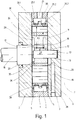
- the pump housing is formed by the pump casing 1 and the end plates 2 and 3, which are stacked on top of one another.
- the housing shell 1 has a circular cylindrical interior, in the cylindrical inner shell of which a circumferential groove 4 is pierced.
- the outer wheel 6 is fastened on the webs 5 which stop laterally.
- the entire package consisting of housing shell 1, end plates 2 and 3 and outer wheel 6 is held together by a screw 7.
- the screw connection 7 penetrates the outer wheel in the region of the tooth heads with holes 8.
- the outer wheel has internal teeth.
- the interior of the pump is thus circumscribed by the internal toothing with tip circle 9 of the outer wheel.
- a pin 10 is firmly inserted at one end.
- the other end of the pin 10 projects into the interior of the pump.
- an eccentric 11 is freely rotatable.
- the axial width of the eccentric corresponds essentially to the axial width of the housing shell 1 and the outer wheel 6.
- the eccentric has a circular cylindrical outer circumference, whose central axis is indicated at 12 and which rotates with the eccentricity E about the axis 13 of the pin 10.
- the inner wheel 14 is freely rotatably mounted on the eccentric 11.
- the inner wheel 14 has external teeth.
- the eccentricity E of the eccentric and the external toothing of the inner wheel are dimensioned and the toothings are designed so that the external toothing of the inner wheel meshes with the internal toothing of the outer wheel. Therefore, the top circles 9 and 15 of the toothing intersect in the circumferential intersections 21 and 22. On the inner circumference of the top circle 9 of the outer wheel, this results in between the intersections 21 and 22 on the one hand on the side of the axis 13, into which the eccentricity E points circumferential engagement area and on the other hand on the side of the axis 13, which faces away from the eccentricity, the circumferential inner sickle space or filling space 23 of the pump.
- the teeth are designed so that the teeth of the outer and inner wheel between the intersections 21 and 22 of the tip circles 9 and 15 are in sealing engagement with their flanks. There are therefore several tooth cells between the intersection points 21 and 22 in the engagement area, which are sealed by touching their flanks to one another and to the inner crescent space 23 facing away from the eccentricity.
- the drive shaft 16 is used to drive the pump.
- the drive shaft 16 is rotatably mounted concentrically to the central axis 13 of the pin 10 in the other end plate 2 and its end is essentially flush with the inside of the pump chamber.
- the shaft 16 forms an end face on which a coupling tab 17 is attached eccentrically. This coupling tab 17 protrudes axially into a driving pocket 18, which in the adjacent end face of the Eccentric 11 is introduced in the area of eccentricity.
- the pump has an essentially radial inlet channel 19 in the end plate 3.
- the inlet channel opens into a distribution space 20 which concentrically surrounds the pin 10.
- the distributor chamber is designed as a circular cylindrical recess in the end face of the end plate, which delimits the pump chamber. Their radius is smaller than the radius of the root circle of the inner wheel, minus the eccentricity E.
- a circular cylindrical recess is made concentrically to the central axis 12 of the eccentric.
- This recess serves as the inlet chamber 28.
- the distributor chamber 20 and the inlet chamber 28 are connected to one another by channels which penetrate the eccentric axially. These channels are preferably designed as grooves of the inner bore of the eccentric and serve to lubricate the slide bearing of the eccentric on the pin 10 and also to cool the eccentric 11.
- the driving pocket 18 serves as such a channel, which therefore axially penetrates the eccentric 11 and with it outer edge revolves on a radius that is slightly larger than the radius of the shaft. Several such channels can also be provided. From Fig.
- the recess 28 is closed off from the inner circumference of the inner wheel by a rib 34 which remains.
- This rib must extend essentially over the entire area of engagement. In other words, this means that the recess may only extend to the inner circumference of the inner wheel on the side of the eccentric bearing facing away from the eccentricity.
- This opening area may only extend at most over the central angle, which is measured on the pump axis 13 and is not greater than the sum of the pitch angle and the central angle of the inner sickle space 23 (opening area) measured on the pump axis 13.
- the rib 34 also has only a small connection opening 35 in the form of a groove made in the end face of the rib in the opening area. This groove lies on the diameter of the eccentric that intersects the pump axis and the eccentric axis, but on the side facing away from the eccentric axis.
- the inner wheel is provided on the end face, which lies in the radial plane of the recess 28, with connecting grooves 36.
- One connecting groove 36 connects each tooth base radially to the inner circumference.
- the outlet channel 24 is located radially in the housing shell 2 and is connected to the circumferential groove 4 of the housing shell. This circumferential groove is limited on the inside by the outer circumference of the outer wheel and forms an outer chamber.
- the outer wheel has at least one outlet bore 25 in the region of each tooth gap.
- Fig. 1 it is shown that in the axial direction two outlet bores (outlet channels) 25.1 and 25.2 are adjacent to each other for each tooth gap.
- the outlet bores are each arranged in parallel radial planes.
- Each outlet bore opens into a pocket 38.
- This pocket is introduced into the outer wheel 6 from the outer circumference of the outer wheel.
- Each pocket is characterized by the fact that it has a larger cross section than the respective outlet bore 25.1 and 25.2, the diameter of which is as small as possible and forms a diameter step with the pocket.
- the pocket is circular cylindrical like the outlet bore.
- the pocket can also be designed as a groove which is milled into the outer circumference of the outer wheel in the circumferential direction or axially parallel, the bottom of the groove is wider than the diameter of the outlet bores 25.1 and 25.2, is flat and preferably intersects the outlet bores at a right angle.
- a check valve is housed in each pocket 38 thus formed. It can be z. B. act as a spring tongue when the pocket 38 is designed as a groove. Such an embodiment is the subject of Fig. 4.
- the pocket can also be designed as a groove which extends over the entire circumference of the outer wheel and whose width is greater than the diameter of the outlet bores 25.1 and 25.2.
- the bottom of the groove of this circumferential groove is covered by an elastic valve ring, which covers all the outlet bores which open onto the bottom of the groove (see FIGS. 1, 2).
- the valve ring is preferably cut in an axial plane and one end is held in place by a rivet while the other end is free to move.
- the drive shaft 16 is driven with the direction of rotation 31.
- the clutch tab 17 engages in the driving pocket 18 of the eccentric and takes the eccentric with it.
- the inner wheel 14 executes a wobbling movement in the interior of the pump, whereby it rotates in the direction of rotation 32 due to the engagement of its toothing with the toothing of the outer wheel. It forms with the toothing of the outer wheel in the engagement area between the intersections 21, 22 of the two tip circles, a plurality of tooth cells, which continuously enlarge and reduce. In the trailing area, the cells enlarge until they open and come into contact with the inner sickle space 23 filled with oil. The cells shrink on the leading side of the inner wheel. So here the oil is put under pressure. If the pressure in a cell exceeds the system pressure prevailing in the circumferential groove 4, the check valves 26.1 and 26.2 are lifted there from the outlet bores 25.1, 25.2 due to the pressure difference, so that the oil can be expelled from the cell.
- the distribution space is connected to the recess 28 through the driver pocket 18 which penetrates the eccentric axially and / or through connecting channels 29.
- the connecting channels 29 are designed as grooves in the inner circumference of the slide bearing of the eccentric. In the area of the slide bearing of the eccentric 11, this creates a good lubricating film, which is used both for lubrication and for hydrodynamic support.
- connection opening 35 and / or the connection grooves 36 are now dimensioned such that they only bring about a throttling connection.
- the amount of oil entering the filling chamber 23 is limited by the speed-dependent time in which the connecting opening 35 and the connecting grooves 36 are each in alignment. The throttling at this point prevents the seal 37 from being exposed to a pressure difference.
- Fig. 3 shows the formation of the teeth based on the detailed radial section of a tooth of the inner wheel, which engages between two adjacent teeth of the outer wheel at bottom dead center.
- the tooth 39 of the inner wheel almost completely fills the tooth gap between the two teeth 40 of the outer wheel.
- the left flank of tooth 39 is referred to as the driving flank 41.
- the flank 41 transmits the torque to the inner wheel by contact with the corresponding counter flank of the external tooth. There is therefore no play between the driving flanks of the inner tooth 39 and the outer tooth 40.
- the flank 42 which is not driving, does not form a further passage, as usual, but a narrow gap with the corresponding counter flank of the outer tooth 40.
- the tooth root spaces 43 and 44 are connected to one another via this gap, which has the quality of a sealing gap.
- 43 is the footwell of the outer wheel (outer footwell) and 44 the footwell of the inner wheel (inner footwell).
- the gap width is 20 to 60 ⁇ m.
- the tooth flank of the inner tooth 39 is withdrawn, so that the foot space 43, ie the outer cell 43, results over the width of the head and the non-driving flank 42 outside the pitch circle 45.
- the inner footwell (inner cell) 44 is formed in that only the top flank of the outer tooth is withdrawn from the bottom of the tooth space.
- the outer cell and inner cell have a width between 60 ⁇ m and 300 ⁇ m.
- the outlet bore 25 is as short as is responsible for strength reasons, preferably shorter than 5 mm.
- the outlet bore 25 opens into a pocket 38.
- the pocket 38 is of circular cylindrical design.
- the diameter of the pocket 38 is larger than the diameter of the outlet bore 25.
- the diameter step between the pocket 38 and the outlet bore 25 is flat and designed as a valve seat.
- a check valve 26 rests on this valve seat.
- This check valve is designed as a circular cylindrical valve plate. It is loaded by a spring 46.
- the spring 46 is supported on the outside on the spring holder 47.
- the spring holder is attached to the outer circumference of the outer wheel. It is a bracket that spans the pocket 38.
- the pocket 38 is designed as an axially parallel groove.
- This groove is made in the outer circumference of the outer wheel.
- two outlet bores 25.1 and 25.2 open.
- the bottom of the groove is flat.
- a spring plate is attached centrally as an outlet valve 26.
- the two free ends of the spring plate rest resiliently on the outlet bores 25.1 and 25.2. 3 and 4 ensure that the outlet bores 25 have only a very small volume to have.
- the volume is limited on the one hand by the required outlet cross-section and on the other hand by strength considerations. In this context, the volume of the outlet bores is minimized.
- the outlet bore is understood to mean the channel section between the external tooth cell space and the check valve.
- the bag represents part of the pressure space insofar as it also allows the pressure to spread without resistance.
Description
Die Erfindung betrifft eine Innenzahnradpumpe nach dem Oberbegriff des Anspruches 1.The invention relates to an internal gear pump according to the preamble of
Diese Pumpe ist bekannt durch die EP-A-0474001 (Bag. 1840).This pump is known from EP-A-0474001 (Bag. 1840).
Es ist in dieser EP-A-0474001 dargestellt, daß im unteren Totpunkt, d. h., dort, wo die Zähne des Innenrades am weitesten in die Zahnlücken des Außenrades eintauchen, zwischen den Flanken von Innenrad und Außenrad kein Spiel besteht. Die EP-A-0 474 001 enthält in dieser Hinsicht keine ausdrückliche Lehre oder sonstige Angabe. Die Darstellung ist daher als zufällig anzusehen. Eine solche Ausführung erweist sich als falsch, da in den Flügelfußräumen des Innenrades sehr hohe Druckspitzen auftreten, die bestenfalls mit einer unangenehmen Geräuschbildung, schlimmstenfalls mit einer unzulässigen Belastung der Pumpe verbunden sind.It is shown in EP-A-0474001 that at bottom dead center, i.e. that is, where the teeth of the inner wheel are most immersed in the tooth gaps of the outer wheel, there is no play between the flanks of the inner wheel and the outer wheel. EP-A-0 474 001 contains no explicit teaching or other information in this regard. The representation is therefore considered to be random. Such a design proves to be wrong, since very high pressure peaks occur in the wing foot wells of the inner wheel, which at best are associated with an unpleasant noise, at worst with an impermissible load on the pump.
Es ist andererseits durch die EP-A-0 315 878 bekannt, daß zwischen den Zahnzellen, die einerseits in den Zahnlücken dea Außenrades (Außenzellen), andererseits am Innenrad (Innenzellen), gebildet werden, eine Verbindung bestehen sollte. Es stellt sich nunmehr jedoch heraus, daß diese Lehre spezifisch ist für bestimmte Pumpentypen, insbesondere für Innenzahnradpumpen, bei denen das Außenrad frei drehbar und das Innenrad angetrieben ist.On the other hand, it is known from EP-A-0 315 878 that there should be a connection between the tooth cells which are formed on the one hand in the tooth gaps of the outer wheel (outer cells) and on the other hand on the inner wheel (inner cells). It turns out, however, that this teaching is specific to certain types of pumps, especially for internal gear pumps, in which the outer wheel is freely rotatable and the inner wheel is driven.
Der Erfindung liegt die Aufgabe zugrunde, eine wesentliche Geräuschminderung zu bewirken. Dabei ist diese Aufgabe insbesondere auf Pumpen der folgenden Bauart gerichtet: Das Außenrad ist stationär und drehfest gelagert, das Innenrad ist auf einem Exzenter frei drehbar gelagert. Der Exzenter sitzt exzentrisch auf der Antriebswelle, welche konzentrisch zum Außenrad gelagert ist.The invention has for its object to bring about a substantial reduction in noise. This task is aimed in particular at pumps of the following type: The outer wheel is mounted stationary and rotatably, the inner wheel is freely rotatable on an eccentric. The eccentric sits eccentrically on the drive shaft, which is mounted concentrically to the outer wheel.
Die Lösung ergibt sich aus dem Kennzeichen des Anspruches 1. Bisher galt es, den Eingriff der Zähne im unteren Totpunkt so zu gestalten, daß Außen- und Innenzellen gut miteinander verbunden sind. Die Zellengröße im unteren Totpunkt galt als Dämpfungsraum und sollte der Geräuschminderung dienen - das Gegenteil stellte sich als richtig heraus.The solution results from the characterizing part of
Bei dieser Ausgestaltung ist es möglich, den Geräuschpegel um 10 dba zu senken.With this configuration, it is possible to reduce the noise level by 10 dba.
Eine weitere Geräuschminderung ergibt sich nach Anspruch 2 und Anspruch 3.A further noise reduction results from
Alle diese Maßnahmen zielen darauf ab, zwar einerseits einen Ölfluß zwischen den Zahnzellen eines in Eingriff befindlichen Zahnpaares zu ermöglichen, andererseits aber den Totraum sehr klein zu halten. Als Totraum wird das Volumen der Zahnzellen bezeichnet, die an einem im unteren Totpunkt im Eingriff befindlichen Zahnpaar entstehen. Aus diesem Grunde erstreckt sich der Spalt mit seiner engen Spaltweite jedenfalls zwischen dem Kopfkreis des Außenrades und dem Wälzkreis. Zwischen dem Wälzkreis und dem Kopfkreis des Innenrades ist eine Vergrößerung der Spaltweite vorgesehen. Eine besondere Bedeutung kommt auch der Ausgestaltung der Auslaßkanäle zu. Der Auslaßkanal ist der Verbindungskanal zwischen der jeweiligen Zapfstelle und dem Druckraum, in dem das Öl aller Zellen gesammelt und zu den Verbrauchern weitergeleitet wird. Die Auslaßkanäle bzw. Auslaßbohrungen müssen kurz, vorzugsweise kürzer als 5 mm sein, bevor sie in den Druckraum einmünden, in welchem der Druck sich widerstandslos festsetzen kann.All of these measures aim, on the one hand, to allow oil flow between the tooth cells of an engaged pair of teeth, but on the other hand to keep the dead space very small. The dead space is the volume of the tooth cells that arise at a pair of teeth in engagement at the bottom dead center. For this reason, the gap with its narrow gap width extends in any case between the tip circle of the outer wheel and the pitch circle. An increase in the gap width is provided between the pitch circle and the tip circle of the inner wheel. The design of the outlet channels is also of particular importance. The outlet channel is the connection channel between the respective tap and the Pressure chamber in which the oil from all cells is collected and passed on to consumers. The outlet channels or outlet bores must be short, preferably shorter than 5 mm, before they open into the pressure chamber, in which the pressure can settle without resistance.
Im folgenden wird die Erfindung anhand eines Ausführungsbeispieles beschrieben. Dabei zeigen ...
- Fig. 1
- einen Achsialschnitt;
- Fig. 2
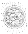
- einen Radialschnitt;
- Fig. 3
- ein Detail des Radialschnittes.
- Fig. 1
- an axial section;
- Fig. 2
- a radial section;
- Fig. 3
- a detail of the radial section.
Das Pumpengehäuse wird gebildet durch den Pumpenmantel 1 und die Stirnplatten 2 und 3, die aufeinandergeschichtet sind. Der Gehäusemantel 1 weist einen kreiszylindrischen Innenraum auf, in dessen zylindrischen Innenmantel eine umlaufende Nut 4 eingestochen ist. Auf den seitlich stehenbleibenden Stegen 5 ist das Außenrad 6 befestigt. Das gesamte Paket aus Gehäusemantel 1, Stirnplatten 2 und 3 sowie Außenrad 6 wird durch eine Verschraubung 7 zusammengehalten. Die Verschraubung 7 durchdringt mit Löchern 8 das Außenrad im Bereich der Zahnköpfe.The pump housing is formed by the
Das Außenrad weist eine Innenverzahnung auf. Der Innenraum der Pumpe wird also durch die Innenverzahnung mit Kopfkreis 9 des Außenrades umschrieben. In der Stirnplatte 3 ist ein Zapfen 10 mit einem Ende fest eingefügt. Das andere Ende des Zapfens 10 ragt in den Innenraum der Pumpe. Auf dem Zapfen 10 ist ein Exzenter 11 frei drehbar gelagert. Die axiale Breite des Exzenters entspricht im wesentlichen der axialen Breite des Gehäusemantels 1 und des Außenrades 6. Der Exzenter besitzt einen kreiszylindrischen Außenumfang, dessen Mittelachse bei 12 angedeutet ist und der mit der Exzentrizität E um die Achse 13 des Zapfens 10 umläuft. Auf dem Exzenter 11 ist das Innenrad 14 frei drehbar gelagert. Das Innenrad 14 weist eine Außenverzahnung auf. Die Exzentrizität E des Exzenters und die Außenverzahnung des Innenrades sind so dimensioniert und die Verzahnungen sind so ausgeführt, daß die Außenverzahnung des Innenrades mit der Innenverzahnung des Außenrades kämmt.
Daher schneiden sich die Kopfkreise 9 und 15 der Verzahnung in den umlaufenden Schnittpunkten 21 und 22. Auf dem Innenumfang des Kopfkreises 9 des Außenrades entstehen dadurch zwischen den Schnittpunkten 21 und 22 einerseits auf der Seite der Achse 13, in die die Exzentrizität E weist, der umlaufende Eingriffsbereich und andererseits auf der Seite der Achse 13, die von der Exzentrizität abgewandt ist, der umlaufende Innen-Sichelraum oder Füllraum 23 der Pumpe.The outer wheel has internal teeth. The interior of the pump is thus circumscribed by the internal toothing with tip circle 9 of the outer wheel. In the
Therefore, the
Die Verzahnung ist so ausgeführt, daß die Zähne des Außen- und Innenrades zwischen den Schnittpunkten 21 und 22 der Kopfkreise 9 und 15 mit ihren Flanken in dichtendem Eingriff sind. Es entstehen daher zwischen den Schnittpunkten 21 und 22 im Eingriffsbereich mehrere Zahnzellen, die durch Berührung ihrer Flanken zueinander und zu dem von der Exzentrizität abgewandten Innensichelraum 23 abgedichtet sind.The teeth are designed so that the teeth of the outer and inner wheel between the
Zum Antrieb der Pumpe dient die Antriebswelle 16. Die Antriebswelle 16 ist konzentrisch zur Mittelachse 13 des Zapfens 10 in der anderen Stirnplatte 2 drehbar gelagert und schließt mit ihrem Ende im wesentlichen bündig mit der Innenseite der Pumpenkammer ab. Dort bildet die Welle 16 eine Stirnfläche, an der exzentrisch ein Kupplungslappen 17 befestigt ist. Dieser Kupplungslappen 17 ragt axial in eine Mitnehmertasche 18, die in die benachbarte Stirnfläche des Exzenters 11 im Bereich der Exzentrizität eingebracht ist.The
Als Einlaß besitzt die Pumpe einen im wesentlichen radialen Einlaßkanal 19 in der Stirnplatte 3. Der Einlaßkanal mündet in einen Verteilerraum 20 ein, der den Zapfen 10 konzentrisch umgibt. Der Verteilerraum ist als kreiszylindrische Ausnehmung der Stirnfläche der Stirnplatte ausgebildet, die den Pumpenraum begrenzt. Ihr Radius ist kleiner als der Radius des Fußkreises des Innenrades, vermindert um die Exzentrizität E.As the inlet, the pump has an essentially
In der Stirnfläche der gegenüberliegenden Seite des Exzenters 11 ist eine kreiszylindrische Ausnehmung konzentrisch zu der Mittelachse 12 des Exzenters eingebracht. Diese Ausnehmung dient als Einlaßkammer 28. Der Verteilerraum 20 und die Einlaßkammer 28 sind durch Kanäle, welche den Exzenter axial durchdringen, miteinander verbunden. Diese Kanäle sind vorzugsweise als Nuten der Innenbohrung des Exzenters ausgebildet und dienen der Schmierung des Gleitlagers des Exzenters auf dem Zapfen 10 wie auch der Kühlung des Exzenters 11. Als ein solcher Kanal dient die Mitnehmertasche 18, die deshalb den Exzenter 11 axial durchdringt und mit ihrer äußeren Kante auf einem Radius umläuft, der etwas größer ist als der Radius der Welle. Es können auch mehrere solcher Kanäle vorgesehen sein. Aus Fig. 2 ergeben sich zwei weitere solcher Schmierkanäle 29 und 30 im Gleitlagerbereich des Innenrades, die in Umfangsrichtung des Mantels des Exzenters 11 jeweils um 60° versetzt sind. Entsprechende Kanäle können auch in der Innenbohrung des Exzenters angelegt sein, so daß durch den in diesen Kanälen 29, 30 und in der Mitnehmertasche 18 fließenden Ölstrom eine symmetrische Verteilung des Öls und gleichzeitig hydrodynamische Abstützung des Exzenters bewirkt wird. Dabei kommt diesen Ölströmen aber insbesondere auch die Funktion der Kühlung des Exzenters zu. Diese Funktion der Kühlung ist deswegen von besonderer Wichtigkeit, weil der Exzenter selbst in seiner Innenbohrung drehbar gelgagert ist und auf seinem Außenmantel als drehbare Lagerung des Innenrades dient.In the end face of the opposite side of the eccentric 11, a circular cylindrical recess is made concentrically to the
Die Ausnehmung 28 ist gegenüber dem Innenumfang des Innenrades durch stehenbleibende Rippe 34 verschlossen. Diese Rippe muß sich im wesentlichen über den gesamten Eingriffsbereich erstrecken. Das heißt mit anderen Worten, daß die Ausnehmung lediglich auf der von der Exzentrizität abgewandten Seite der Exzenterlagerung bis auf den Innenumfang des Innenrades reichen darf. Dieser Öffnungsbereich darf sich lediglich maximal über den Zentriwinkel erstrekken, der an der Pumpenachse 13 gemessen wird und nicht größer ist als die Summe aus Teilungswinkel und dem an der Pumpenachse 13 gemessenen Zentriwinkel des Innen-Sichel-raums 23 (Öffnungsbereich).The
In Fig. 2 ist dargestellt, daß die Rippe 34 auch im Öffnungsbereich lediglich eine kleine Verbindungsöffnung 35 in Form einer in die Stirnseite der Rippe eingebrachten Nut aufweist. Diese Nut liegt auf dem Durchmesser des Exzenters, der die Pumpenachse und die Exzenterachse schneidet, jedoch auf der von der Exzenterachse abgewandten Seite.In Fig. 2 it is shown that the
Das Innenrad ist auf der Stirnseite, die in der Radialebene der Ausnehmung 28 liegt, mit Verbindungsnuten 36 versehen. Jeweils eine Verbindungsnut 36 verbindet je einen Zahngrund radial mit dem Innenumfang.The inner wheel is provided on the end face, which lies in the radial plane of the
Der Auslaßkanal 24 liegt radial im Gehäusemantel 2 und ist mit der Umfangsnut 4 des Gehäusemantels verbunden. Diese Umfangsnut wird nach innen durch den Außenumfang des Außenrades begrenzt und bildet eine Außenkammer.The
Das Außenrad weist im Bereich jeder Zahnlücke mindestens eine Auslaßbohrung 25 auf. In Fig. 1 ist gezeigt, daß in axialer Richtung pro Zahnlücke jeweils zwei Auslaßbohrungen (Auslaßkanäle) 25.1 und 25.2 nebeneinander liegen. Dabei sind die Auslaßbohrungen jeweils in parallelen Radialebenen angeordnet.The outer wheel has at least one outlet bore 25 in the region of each tooth gap. In Fig. 1 it is shown that in the axial direction two outlet bores (outlet channels) 25.1 and 25.2 are adjacent to each other for each tooth gap. The outlet bores are each arranged in parallel radial planes.
Jede Auslaßbohrung mündet in einer Tasche 38. Diese Tasche ist vom Außenumfang des Außenrades her in das Außenrad 6 eingebracht. Jede Tasche zeichnet sich dadurch aus, daß sie einen größeren Querschnitt hat als die jeweilige Auslaßbohrung 25.1 und 25.2, deren Durchmesser möglichst klein ist und mit der Tasche eine Durchmesserstufe bildet. Damit ist allerdings nicht gesagt, daß die Tasche kreiszylindrisch ist wie der Auslaßbohrung. Vielmehr kann die Tasche auch als Nut ausgebildet sein, die in den Außenumfang des Außenrades in Umfangsrichtung oder achsparallel eingefräst ist, deren Nutengrund breiter ist als der Durchmesser der Auslaßbohrungen 25.1 und 25.2, eben ist und vorzugsweise die Auslaßbohrungen unter einem rechten Winkel schneidet.Each outlet bore opens into a
In jeder auf diese Weise gebildeten Tasche 38 ist ein Rückschlagventil untergebracht. Dabei kann es sich z. B. um eine Federzunge handeln, wenn die Tasche 38 als Nut ausgeführt ist. Eine solche Ausführung ist Gegenstand von Fig. 4. Die Tasche kann aber auch als Nut ausgebildet sein, die sich über den gesamten Umfang des Außenrades erstreckt und deren Breite größer ist als der Durchmesser des Auslaßbohrungen 25.1 und 25.2. Der Nutengrund dieser umlaufenden Nut wird von einem elastischen Ventilring überdeckt, der die sämtlichen Auslaßbohrungen überdeckt, die auf den Nutengrund münden (s. o. in Fig. 1, 2). Der Ventilring wird vorzugsweise in einer Achsialebene durchtrennt und das eine Ende durch eine Niet festgehalten während das andere Ende frei beweglich ist.A check valve is housed in each
Zur Funktion:About the function:
Die Antriebswelle 16 wird mit Drehrichtung 31 angetrieben. Dabei greift der Kupplungslappen 17 in die Mitnehmertasche 18 des Exzenters ein und nimmt den Exzenter mit. Das Innenrad 14 führt dadurch eine taumelnde Bewegung im Innenraum der Pumpe aus, wobei es sich infolge des Eingriffs seiner Verzahnung mit der Verzahnung des Außenrades mit Drehrichtung 32 dreht. Dabei bildet es mit der Verzahnung des Außenrades in dem Eingriffsbereich zwischen den Schnittpunkten 21, 22 der beiden Kopfkreise mehrere Zahnzellen, die sich fortlaufend vergrößern und verkleinern. In dem nachlaufenden Bereich vergrößern sich die Zellen, bis sie sich öffnen und mit dem mit Öl gefüllten Innensichelraum 23 in Verbindung kommen. Auf der vorlaufenden Seite des Innenrades verkleinern sich die Zellen. Hier wird also das Öl unter Druck gesetzt. Wenn der Druck in einer Zelle den in der Umfangsnut 4 herrschenden Systemdruck übersteigt, werden dort die Rückschlagventile 26.1 und 26.2 von den Auslaßbohrungen 25.1, 25.2 infolge der Druckdifferenz abgehoben, so daß das Öl aus der Zelle ausgestoßen werden kann.The
Infolge des auf der Einlaßseite entstehenden Unterdrucks wird Öl aus dem Einlaßkanal 19 angesaugt. Hierbei gelangt das Öl zunächst in den Verteilerraum 20. Der Verteilerraum steht durch die den Exzenter axial durchdringende Mitnehmertasche 18 und/oder durch Verbindungskanäle 29 mit der Ausnehmung 28 in Verbindung. Die Verbindungskanäle 29 sind als Nuten im Innenumfang des Gleitlagers des Exzenters ausgeführt. Im Bereich der Gleitlagerung des Exzenters 11 entsteht hierdurch ein guter Schmierfilm, der gleichzeitig zur Schmierung und zur hydrodynamischen Abstützung dient.As a result of the negative pressure arising on the inlet side, oil is sucked out of the
Infolge der Drehung des Exzenters mit Drehrichtung 31 dreht sich das Innenrad mit Drehrichtung 32. Daher führt das Zahnrad eine Relativbewegung zu dem Exzenter und zu der radialen Verbindungsöffnung 35 in der Außenrippe 34 des Exzenters aus. Daher wird über die Verbindungsnuten 36 in der Stirnfläche des Innenrades eine intermittierende Verbindung zwischen der Ausnehmung 28 und dem Innen-Sichelraum (gleich Füllraum) 23 der Pumpe hergestellt. Die Verbindungsöffnung 35 und/oder die Verbindungsnuten 36 sind nun so dimensioniert, daß sie lediglich eine drosselnde Verbindung bewirken. Außerdem wird die in den Füllraum 23 gelangende Ölmenge begrenzt durch die drehzahlabhängige Zeit, in der die Verbindungsöffnung 35 und die Verbindungsnuten 36 jeweils fluchten. Durch die Drosselung an dieser Stelle wird vermieden, daß die Dichtung 37 einer Druckdifferenz ausgesetzt ist.As a result of the rotation of the eccentric with the direction of
Fig. 3 zeigt die Ausbildung der Zähne anhand des im Detail dargestllten Radialschnittes eines Zahnes des Innenrades, der im unteren Totpunkt zwischen zwei benachbarte Zähne des Außenrades eingreift. Im unteren Totpunkt füllt der Zahn 39 des Innenrades die Zahnlücke zwischen den beiden Zähnen 40 des Außenrades fast vollständig aus. Dabei sei die linke Flanke des Zahnes 39 als die treibende Flanke 41 bezeichnet. Das bedeutet, daß bei gegebener Drehrichtung der Pumpenwelle und des Exzenters die Flanke 41 durch Kontakt mit der entsprechenden Gegenflanke des Außenzahnes das Drehmoment auf das Innenrad überträgt. Zwischen den treibenden Flanken von Innenzahn 39 und Außenzahn 40 besteht daher kein Spiel. In diesem Zustand bildet die Flanke 42, die nicht treibend ist, mit der entsprechenden Gegenflanke des Außenzahnes 40 nicht - wie üblich - einen weiteren Durchlaß sondern einen engen Spalt. Über diesen Spalt, der die Qualität eines Dichtspaltes hat, sind die Zahnfußräume 43 und 44 miteinander verbunden. Dabei ist 43 der Fußraum des Außenrades (Außenfußraum) und 44 der Fußraum des Innenrades (Innenfußraum). Die Spaltweite beträgt 20 bis 60 µm. Außerhalb des Wälzkreises 45 ist die Zahnflanke des Innenzahnes 39 zurückgenommen, so daß sich über die Breite des Kopfes und der nicht treibenden Flanke 42 außerhalb des Wälzkreises 45 der Fußraum 43, d. h. die Außenzelle 43, ergibt. Der Innenfußraum (Innenzelle) 44 wird dadurch gebildet, daß lediglich die Kopfflanke des Außenzahnes gegenüber dem Zahnlücken-Grund zurückgenommen ist. Die Außenzelle und Innenzelle haben eine Weite zwischen 60 µm und 300 µm.Fig. 3 shows the formation of the teeth based on the detailed radial section of a tooth of the inner wheel, which engages between two adjacent teeth of the outer wheel at bottom dead center. At bottom dead center, the
Die Auslaßbohrung 25 ist so kurz, wie dies aus Festigkeitsgründen zu verantworten ist, vorzugsweise kürzer als 5 mm. Die Auslaßbohrung 25 mündet in einer Tasche 38. In diesem Ausführungsbeispiel ist die Tasche 38 kreiszylindrisch ausgeführt. Der Durchmesser der Tasche 38 ist größer als der Durchmesser der Auslaßbohrung 25. Die Durchmesserstufe zwischen der Tasche 38 und der Auslaßbohrung 25 ist eben und als Ventilsitz ausgebildet. Auf diesem Ventilsitz liegt ein Rückschlagventil 26 auf. Dieses Rückschlagventil ist als kreiszylindrisches Ventilplättchen ausgebildet. Es wird durch eine Feder 46 belastet. Die Feder 46 stützt sich nach außen an dem Federhalter 47 ab. Der Federhalter ist auf dem Außenumfang des Außenrades befestigt. Es handelt sich dabei um einen Bügel, der die Tasche 38 überspannt.The outlet bore 25 is as short as is responsible for strength reasons, preferably shorter than 5 mm. The outlet bore 25 opens into a
Bei der Ausführung nach Fig. 4 ist die Tasche 38 als achsparallele Nut ausgeführt. Diese Nut ist in dem Außenumfang des Außenrades eingebracht. Im Grunde der Nut münden zwei Auslaßbohrungen 25.1 und 25.2. Der Nutengrund ist eben. Auf dem Nutengrund ist als Auslaßventil 26 eine Federplatte mittig befestigt. Die beiden freien Enden der Federplatte liegen federnd auf den Auslaßbohrungen 25.1 und 25.2 auf. Beide Ausführungen nach Fig. 3 und Fig. 4 gewährleisten, daß die Auslaßbohrungen 25 nur ein sehr geringes Volumen haben. Das Volumen ist zum einen durch den erforderlichen Auslaßquerschnitt, zum anderen durch Festigkeitserwägungen begrenzt. In diesem Rahmen wird das Volumen der Auslaßbohrungen minimiert. Dabei wird unter Auslaßbohrung der Kanalabschnitt zwischen dem Außen-Zahnzellenraum und dem Rückschlagventil verstanden.
Die Tasche stellt insofern einen Teil des Druckraumes dar, als sie ebenfalls eine widerstandsfreie Ausbreitung des Drucks gestattet.4, the
The bag represents part of the pressure space insofar as it also allows the pressure to spread without resistance.
- 11
- Gehäusemantel, PumpenmantelHousing jacket, pump jacket
- 22nd
- StirnplatteFaceplate
- 33rd
- StirnplatteFaceplate
- 44th
- Nut, DruckraumGroove, pressure chamber
- 55
- StegeWalkways
- 66
- AußenradOuter wheel
- 77
- VerschraubungScrew connection
- 88th
- LöcherHoles
- 99
- KopfkreisHead circle
- 1010th
- ZapfenCones
- 1111
- Exzentereccentric
- 1212th
- MittelachseCentral axis
- 1313
- Achseaxis
- 1414
- InnenradInner wheel
- 1515
- KopfkreisHead circle
- 1616
- Antriebswelledrive shaft
- 1717th
- KupplungslappenClutch tab
- 1818th
- Mitnehmertasche, LochTakeaway pocket, hole
- 1919th
- EinlaßkanalInlet duct
- 2020th
- VerteilerraumDistribution room
- 2121
- SchnittpunktIntersection
- 2222
- SchnittpunktIntersection
- 2323
- InnensichelraumInternal sickle room
- 2424th
- AuslaßkanalExhaust duct
- 25.125.1
- AuslaßbohrungOutlet bore
- 25.225.2
- AuslaßbohrungOutlet bore
- 26.126.1
- Ventilring, RückschlagValve ring, kickback
- 26.226.2
- Ventilring, RückschlagValve ring, kickback
- 2727
- EinlaßflächeInlet area
- 2828
- Einlaßkammer, AusnehmungInlet chamber, recess
- 2929
- Schmierkanal, VerbindungskanalLubrication channel, connection channel
- 3030th
- Schmierkanal, VerbindungskanalLubrication channel, connection channel
- 3131
- DrehrichtungDirection of rotation
- 3232
- DrehrichtungDirection of rotation
- 3333
- Drosselthrottle
- 3434
- Ripperib
- 3535
- VerbindungsöffnungConnection opening
- 3636
- VerbindungsnutConnecting groove
- 3737
- Dichtungpoetry
- 3838
- Taschebag
- 3939
- Zahn des InnenradesTooth of the inner wheel
- 4040
- Zahn des AußenradesTooth of the outer wheel
- 4141
- treibende Flankedriving flank
- 4242
- nicht treibende Flankenon-driving edge
- 4343
- AußenfußraumOutdoor footwell
- 4444
- InnenfußraumInterior footwell
- 4545
- WälzkreisPitch circle
- 4646
- Federfeather
Claims (4)
- An internal gear pump for hydraulic fluids, in which each tooth cell is provided with an outlet duct (25) and an outlet valve (26) respectively, and in which the tooth cells are very small at bottom dead centre of the area of engagement,
characterised in that
the teeth of an internal gear (14) and an external gear (6) are formed in such a manner that at bottom dead centre of the area of engagement the non-operative flanks of the meshing teeth (39, 40) form a gap with 20 to 60 µm clearance. - An internal gear pump according to Claim 1,
characterised in that
the gap extends radially outside the pitch circle to provide a clearance in excess of 60µm but less than 300 µm. - An internal gear pump according to Claim 1 or 2,
characterised in that
the length of each outlet duct (25) between the tooth cell and a pressure chamber is less than 5 mm. - A pump according to any one of Claims 1 to 3,
characterised in thateach outlet duct (25) starts radially from the tooth spaces of the external gear and opens into a pocket (38) in each case,the pocket (38) is introduced from the external periphery of the external gear (6) into the external gear (6),and a spring-loaded outlet valve (26) is mounted in each pocket (38).
Applications Claiming Priority (2)
| Application Number | Priority Date | Filing Date | Title |
|---|---|---|---|
| DE4221326 | 1992-06-29 | ||
| DE4221326 | 1992-06-29 |
Publications (2)
| Publication Number | Publication Date |
|---|---|
| EP0579981A1 EP0579981A1 (en) | 1994-01-26 |
| EP0579981B1 true EP0579981B1 (en) | 1996-10-23 |
Family
ID=6462083
Family Applications (1)
| Application Number | Title | Priority Date | Filing Date |
|---|---|---|---|
| EP93110326A Expired - Lifetime EP0579981B1 (en) | 1992-06-29 | 1993-06-29 | Internal gear pump for hydraulic fluids |
Country Status (2)
| Country | Link |
|---|---|
| EP (1) | EP0579981B1 (en) |
| DE (1) | DE59304256D1 (en) |
Families Citing this family (9)
| Publication number | Priority date | Publication date | Assignee | Title |
|---|---|---|---|---|
| IT1271052B (en) * | 1993-11-18 | 1997-05-26 | INTERNAL GEAR PUMP WITH VOLUMETRIC PROJECTIONS | |
| CA2979688C (en) | 2015-03-16 | 2021-09-21 | Saudi Arabian Oil Company | Equal-walled gerotor pump for wellbore applications |
| DE102016121240A1 (en) * | 2016-11-07 | 2018-05-09 | Nidec Gpm Gmbh | Electric gerotor pump and method of making same |
| US11371326B2 (en) | 2020-06-01 | 2022-06-28 | Saudi Arabian Oil Company | Downhole pump with switched reluctance motor |
| US11499563B2 (en) | 2020-08-24 | 2022-11-15 | Saudi Arabian Oil Company | Self-balancing thrust disk |
| US11920469B2 (en) | 2020-09-08 | 2024-03-05 | Saudi Arabian Oil Company | Determining fluid parameters |
| US11644351B2 (en) | 2021-03-19 | 2023-05-09 | Saudi Arabian Oil Company | Multiphase flow and salinity meter with dual opposite handed helical resonators |
| US11591899B2 (en) | 2021-04-05 | 2023-02-28 | Saudi Arabian Oil Company | Wellbore density meter using a rotor and diffuser |
| US11913464B2 (en) | 2021-04-15 | 2024-02-27 | Saudi Arabian Oil Company | Lubricating an electric submersible pump |
Family Cites Families (5)
| Publication number | Priority date | Publication date | Assignee | Title |
|---|---|---|---|---|
| GB223257A (en) * | 1923-04-16 | 1924-10-16 | Hill Engineering Company Inc | Improvements in rotors for rotary compressors and the like |
| US3139835A (en) * | 1962-08-15 | 1964-07-07 | Davey Compressor Co | Rotary pump or motor |
| DE3444859A1 (en) * | 1983-12-14 | 1985-06-27 | Barmag Barmer Maschinenfabrik Ag, 5630 Remscheid | Rotary cellular pump for hydraulic systems |
| EP0315878B1 (en) * | 1987-11-07 | 1992-04-01 | Barmag Ag | Internal gear pump |
| DE59104131D1 (en) * | 1990-09-01 | 1995-02-16 | Barmag Luk Automobiltech | Internal gear pump for hydraulic fluid. |
-
1993
- 1993-06-29 EP EP93110326A patent/EP0579981B1/en not_active Expired - Lifetime
- 1993-06-29 DE DE59304256T patent/DE59304256D1/en not_active Expired - Fee Related
Also Published As
| Publication number | Publication date |
|---|---|
| DE59304256D1 (en) | 1996-11-28 |
| EP0579981A1 (en) | 1994-01-26 |
Similar Documents
| Publication | Publication Date | Title |
|---|---|---|
| EP0362906B1 (en) | Internal gear pump | |
| DE102005041579B4 (en) | Internal gear pump with filling piece | |
| DE2552256C3 (en) | Hydrostatic axial piston machine | |
| DE2240632A1 (en) | ROTARY PISTON MACHINE FOR LIQUIDS | |
| DE19613833A1 (en) | Gear pump with meshing internal and external toothed wheels | |
| DE3743976A1 (en) | DEVICE FOR TORQUE TRANSMISSION | |
| EP0579981B1 (en) | Internal gear pump for hydraulic fluids | |
| DE2837821C2 (en) | ||
| DE3532602C2 (en) | Flow control valve | |
| DE60029659T2 (en) | Vane pump | |
| DE3909319A1 (en) | GEAR MOTOR | |
| DE60031459T2 (en) | Gerotor motor with lubrication grooves | |
| DE3504993C2 (en) | ||
| CH682939A5 (en) | Internal gear pump. | |
| DE102004021216B4 (en) | High-pressure internal gear machine with multiple hydrostatic bearings per ring gear | |
| WO2022263368A1 (en) | Gear pump having a bearing flushing system and adjustable radial gap | |
| EP0474001B1 (en) | Internal gear pump for hydraulic fluids | |
| EP0475109B1 (en) | Internal-gear pump for hydraulic fluid | |
| CH667702A5 (en) | GEAR PUMP. | |
| EP0328745B1 (en) | Internal gear machine | |
| DE2902301A1 (en) | CENTRIFUGAL PUMP | |
| EP1764506A2 (en) | Internal gear pump | |
| EP0473025B1 (en) | Internal-gear pump for hydraulic fluid | |
| DE4440782C5 (en) | Internal gear pump with displacement projections | |
| DE2015897A1 (en) | Gear rotary piston machine |
Legal Events
| Date | Code | Title | Description |
|---|---|---|---|
| PUAI | Public reference made under article 153(3) epc to a published international application that has entered the european phase |
Free format text: ORIGINAL CODE: 0009012 |
|
| AK | Designated contracting states |
Kind code of ref document: A1 Designated state(s): DE FR GB IT |
|
| 17P | Request for examination filed |
Effective date: 19940115 |
|
| 17Q | First examination report despatched |
Effective date: 19950301 |
|
| GRAG | Despatch of communication of intention to grant |
Free format text: ORIGINAL CODE: EPIDOS AGRA |
|
| RAP1 | Party data changed (applicant data changed or rights of an application transferred) |
Owner name: LUK AUTOMOBILTECHNIK GMBH & CO. KG |
|
| GRAH | Despatch of communication of intention to grant a patent |
Free format text: ORIGINAL CODE: EPIDOS IGRA |
|
| GRAH | Despatch of communication of intention to grant a patent |
Free format text: ORIGINAL CODE: EPIDOS IGRA |
|
| GRAA | (expected) grant |
Free format text: ORIGINAL CODE: 0009210 |
|
| AK | Designated contracting states |
Kind code of ref document: B1 Designated state(s): DE FR GB IT |
|
| PG25 | Lapsed in a contracting state [announced via postgrant information from national office to epo] |
Ref country code: FR Effective date: 19961023 |
|
| ITF | It: translation for a ep patent filed |
Owner name: RIF. ISCRIZIONE REG.: 13/01/97;BARZANO' E ZANARDO |
|
| REF | Corresponds to: |
Ref document number: 59304256 Country of ref document: DE Date of ref document: 19961128 |
|
| GBT | Gb: translation of ep patent filed (gb section 77(6)(a)/1977) |
Effective date: 19961206 |
|
| EN | Fr: translation not filed | ||
| PLBE | No opposition filed within time limit |
Free format text: ORIGINAL CODE: 0009261 |
|
| STAA | Information on the status of an ep patent application or granted ep patent |
Free format text: STATUS: NO OPPOSITION FILED WITHIN TIME LIMIT |
|
| 26N | No opposition filed | ||
| REG | Reference to a national code |
Ref country code: GB Ref legal event code: IF02 |
|
| PGFP | Annual fee paid to national office [announced via postgrant information from national office to epo] |
Ref country code: DE Payment date: 20070820 Year of fee payment: 15 |
|
| PGFP | Annual fee paid to national office [announced via postgrant information from national office to epo] |
Ref country code: GB Payment date: 20070529 Year of fee payment: 15 |
|
| PGFP | Annual fee paid to national office [announced via postgrant information from national office to epo] |
Ref country code: IT Payment date: 20070628 Year of fee payment: 15 |
|
| GBPC | Gb: european patent ceased through non-payment of renewal fee |
Effective date: 20080629 |
|
| PG25 | Lapsed in a contracting state [announced via postgrant information from national office to epo] |
Ref country code: DE Free format text: LAPSE BECAUSE OF NON-PAYMENT OF DUE FEES Effective date: 20090101 |
|
| PG25 | Lapsed in a contracting state [announced via postgrant information from national office to epo] |
Ref country code: GB Free format text: LAPSE BECAUSE OF NON-PAYMENT OF DUE FEES Effective date: 20080629 |
|
| PG25 | Lapsed in a contracting state [announced via postgrant information from national office to epo] |
Ref country code: IT Free format text: LAPSE BECAUSE OF NON-PAYMENT OF DUE FEES Effective date: 20080629 |