EP0579962A1 - Choke coil - Google Patents
Choke coil Download PDFInfo
- Publication number
- EP0579962A1 EP0579962A1 EP93109880A EP93109880A EP0579962A1 EP 0579962 A1 EP0579962 A1 EP 0579962A1 EP 93109880 A EP93109880 A EP 93109880A EP 93109880 A EP93109880 A EP 93109880A EP 0579962 A1 EP0579962 A1 EP 0579962A1
- Authority
- EP
- European Patent Office
- Prior art keywords
- magnetic
- magnetic means
- choke coil
- coil
- coils
- Prior art date
- Legal status (The legal status is an assumption and is not a legal conclusion. Google has not performed a legal analysis and makes no representation as to the accuracy of the status listed.)
- Granted
Links
Images



Classifications
-
- H—ELECTRICITY
- H01—ELECTRIC ELEMENTS
- H01F—MAGNETS; INDUCTANCES; TRANSFORMERS; SELECTION OF MATERIALS FOR THEIR MAGNETIC PROPERTIES
- H01F3/00—Cores, Yokes, or armatures
- H01F3/10—Composite arrangements of magnetic circuits
-
- H—ELECTRICITY
- H01—ELECTRIC ELEMENTS
- H01F—MAGNETS; INDUCTANCES; TRANSFORMERS; SELECTION OF MATERIALS FOR THEIR MAGNETIC PROPERTIES
- H01F37/00—Fixed inductances not covered by group H01F17/00
-
- H—ELECTRICITY
- H02—GENERATION; CONVERSION OR DISTRIBUTION OF ELECTRIC POWER
- H02M—APPARATUS FOR CONVERSION BETWEEN AC AND AC, BETWEEN AC AND DC, OR BETWEEN DC AND DC, AND FOR USE WITH MAINS OR SIMILAR POWER SUPPLY SYSTEMS; CONVERSION OF DC OR AC INPUT POWER INTO SURGE OUTPUT POWER; CONTROL OR REGULATION THEREOF
- H02M1/00—Details of apparatus for conversion
- H02M1/12—Arrangements for reducing harmonics from AC input or output
- H02M1/126—Arrangements for reducing harmonics from AC input or output using passive filters
-
- H—ELECTRICITY
- H02—GENERATION; CONVERSION OR DISTRIBUTION OF ELECTRIC POWER
- H02M—APPARATUS FOR CONVERSION BETWEEN AC AND AC, BETWEEN AC AND DC, OR BETWEEN DC AND DC, AND FOR USE WITH MAINS OR SIMILAR POWER SUPPLY SYSTEMS; CONVERSION OF DC OR AC INPUT POWER INTO SURGE OUTPUT POWER; CONTROL OR REGULATION THEREOF
- H02M1/00—Details of apparatus for conversion
- H02M1/0064—Magnetic structures combining different functions, e.g. storage, filtering or transformation
Definitions
- the invention relates to a choke coil used in an electronic appliance.
- the input current of a capacitor input rectifying circuit used in the power source of an electronic appliance contains higher harmonics.
- the current with poor waveforms adversely affects the other electronic appliances, and consumes the capacity of power device and power feed line uneconomically, and hence it is desired to decrease the higher harmonics.
- the choke coil is used.
- Fig. 12 shows an example of choke coil.
- a choke coil 19 is composed of a magnetic core 17 having a closed magnetic circuit, and a coil 18 wound thereon.
- Fig. 13 shows a power source circuit of an electronic appliance. It comprises a rectifying and smoothing block 7, noise filter blocks 22, 23 incorporating a common mode choke coil 21, and a choke coil 19.
- the noise filter blocks 22, 23 and choke coil 19 occupy nearly the same space.
- the choke coil 19 and common mode choke coil 21 are demanded to be in compact size. This demand, however, does not match with the requirement that the choke coil 19 must have a large inductance in order to decrease the higher harmonics of the input current.
- the invention therefore presents a choke coil possessing simultaneously the function of decreasing the higher harmonics of the input current and the function as noise filter.
- the power source using the choke coil of the invention is composed without noise filter, and is hence reduced in size.
- the choke coil of the invention is of single constitution, and possesses both the function of normal mode choke coil and common mode choke coil.
- the choke coil of the invention comprises first magnetic means possessing two closed magnetic circuits, second magnetic means, a first piled portion overlapping one of the closed magnetic circuits of the first magnetic means and a part of the second magnetic means, a second piled portion overlapping the other closed magnetic circuit of the first magnetic means and another part of the second magnetic means, a first coil wound around the first piled portion, and a second coil wound around the second piled portion, wherein the winding directions of the both coils are set so that the magnetomotive forces generated by the both coiles may cancel each other within the second magnetic means.
- the first magnetic means and two coils compose the function of the normal mode choke coil necessary for decreasing the higher harmonics of the input current.
- the second magnetic means and two coils compose the function of common mode choke coil necessary for decreasing the noise between the power source line and the ground.
- the magnetic flux leaking from the second magnetic means to the first magnetic means composes a part of the function of the normal mode choke coil.
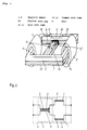
- Fig. 1 is a perspective view of choke coil in a first embodiment of the invention.
- Fig. 2 is an equivalent circuit diagram of the choke coil of the invention.
- Fig. 3 is a circuit diagram using the choke coil of the invention.
- Fig. 4 is a frequency characteristic diagram of inductance in the normal mode of the choke coil shown in Fig. 1.
- Fig. 5 is a frequency characteristic diagram of inductance in the common mode of the choke coil shown in Fig. 1.
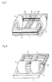
- Fig. 6 is a perspective view of choke coil in a second embodiment of the invention.
- Fig. 7 is a perspective view of choke coil in a third embodiment of the invention.
- Fig. 8 is a perspective view of choke coil in a fourth embodiment of the invention.
- Fig. 9 is a perspective view of choke coil in a fifth embodiment of the invention.
- Fig. 10 is a perspective view of choke coil in a sixth embodiment of the invention.
- Fig. 11 is a perspective view of choke coil in a seventh embodiment of the invention.
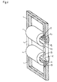
- Fig. 12 is a perspective view of a conventional choke coil.
- Fig. 13 is a circuit diagram using the conventional choke coil.
- Fig. 1 is a perspective view showing a choke coil in the first embodiment of the invention.
- the magnetic means 1 composes two closed magnetic circuits by combination of E-shaped magnetic core and I-shaped magnetic core both made of silicon steel plates.
- the reference number 1j is a magnetic air gap for preventing magnetic saturation.
- One of the closed magnetic circuits of the magnetic means 1 is composed of the right half of a common core leg 1e, right half of magnetic air gap 1j, right half of central core leg 1a, right half of common core leg 1d, and side core leg 1b.
- the other closed magnetic circuit of the magnetic means 1 is composed of the left half of common core leg 1e, left half of magnetic air gap 1j, left half of central core leg 1a, left half of common core leg 1d, and side core leg 1c.
- the magnetic means 2 is a square-shaped magnetic core made of ferrite, which is laid over the magnetic means 1.
- One of the coils 3 is wound around the side core leg 1b of the magnetic means 1 and the magnetic means 2 laid thereover.
- the other coil 3 is wound around the side core leg 1c of the magnetic means 1 and the magnetic means 2 laid thereover.
- the both coils 3 have the same number of turns.
- the winding directions of the two coils 3 are so set that the magnetomotive forces generated by the both coils may cancel each other in the second magnetic means.
- the magnetic means 1 and magnetic means 2 are preferred to have the same dimensions in the mutual piled portions so that the both piled portions may be smooth and that the shape of the coil bobbin covering them may be simple.
- Magnetic fluxes 1f, 1g are generated in the magnetic means 1, and leakage magnetic fluxes 2h, 2i are generated between the magnetic means 1 and magnetic means 2.
- the magnetic fluxes 1f, 1g, 2h, 2i make up a normal mode choke 4 in Fig. 2.
- the magnetic fluxes 2f, 2g generated in the magnetic means 2 make up a common mode choke 5.
- a curve 12 in Fig. 4 shows a frequency characteristic of normal mode of the choke coil 6. This inductance decreases the higher harmonics of the input current.
- the magnetic fluxes 1f, 1g of the magnetic means 1 compose an inductance 2L1 having two coils 3 connected in series, and a curve 10 is obtained.
- the leakage magnetic fluxes 2h, 2i compose a leakage inductance L3, and a curve 11 is obtained.
- a curve 12 is obtained by combining the curve 10 and the curve 11.
- the leakage inductance L3 is not attenuated even at high frequency, and the choke coil of the invention therefore possesses a normal mode inductance of more than 10 times larger at high frequency as compared with that of the conventional choke coil.
- a curve 15 in Fig. 5 shows a frequency characteristic of inductance of common mode of the choke coil 6.
- the magnetic fluxes 1f, 1g of the magnetic means 1 make up an inductance L1 of two coils 3 connected in parallel, and a curve 13 is obtained.
- the magnetic fluxes 2f, 2g and leakage magnetic fluxes 2h, 2i of the magnetic means 2 make up an inductance L2 of two coils 3 connected in parallel, and a curve 14 is obtained.
- a curve 15 is obtained by combining the curve 13 and the curve 14.
- the two coils 3 are wound in a large number of turns in order to obtain a large normal mode inductance, therefore the inductance of the common mode shown by curve 15 is larger than the conventional common mode choke.
- the frequency characteristic of the choke coil 6 shown in Fig. 4 and Fig. 5 may be changed, if necessary, by varying the magnetic characteristics of the magnetic means 1 and magnetic means 2.
- the magnetic material is selected, or the magnetic material composed of plural magnetic materials is selected.
- the magnetic means 1 and magnetic means 2 may be ring-shaped, as well as square-shaped, practically.
- the location of magnetic air gap 1j in the magnetic means 1 is not limited within the core leg 1a, but one or plural locations may be selected over the entire magnetic means 1.
- Fig. 3 shows a constitution of a power source circuit using the choke coil 6 of the invention.
- Numeral 7 is a rectifying and smoothing block, 8 and 9 are capacitors.
- the choke coil 6 prevents noise while simultaneously decreasing the higher harmonics of the input current, therefore the noise filter is not used.
- Fig. 6 is a perspective view showing a choke coil in the second embodiment of the invention.
- Two magnetic means 1 are overlaid in the horizontal direction on both sides of magnetic means 2.
- two coils 3 are wound.
- the both coils 3 have a same number of turns.
- the winding directions of the two coils 3 are so set that the magnetomotive forces generated by the both coils may cancel each other in the second magnetic means.
- Fig. 7 is a perspective view showing a choke coil in the third embodiment of the invention.
- This embodiment is same as Embodiment 1 except that a magnetic air gap 16 is present between the magnetic means 1 and magnetic means 2 by inserting a non-magnetic thin film.
- the presence of the magnetic air gap 16 decreases the leakage magnetic fluxes 2h, 2i, and the magnetic means 2 is not magnetically saturated if a large current flows in the choke coil.
- decrease of leakage magnetic fluxes 2h, 2i brings about a disadvantage of decreasing the normal mode inductance.
- the choke coil of the invention has a normal mode inductance of over ten times larger at high frequency as compared with that of the conventional choke coil, therefore decrease of inductance may be practically ignored.
- Fig. 8 is a perspective view showing a choke coil in the fourth embodiment of the invention.
- the magnetic means 1 composes two closed magnetic circuits by combination of E-shaped magnetic core and I-shaped magnetic core both made of silicon steel plates.
- Reference numeral 1j is a magnetic air gap for preventing magnetic saturation.
- Magnetic means 2 is a square-shaped ferrite core, which is overlaid on a common core leg 1e of the magnetic means 1 in the horizontal direction.
- two coils 3 are wound.
- the both coils 3 have a same number of turns.
- the winding directions of the two coils 3 are so set that the magnetomotive forces generated in both coils may cancel each other in the second magnetic means.
- the two coils 3 are mounted on the common core leg 1e, and hence the distance between the two coils is short. Therefore the magnetic fluxes in the opposite directions created by the two coils in the magnetic means 2 cancel each other almost completely, and, as a result, if a large current flows in the choke coil, the magnetic means 2 will not be saturated magnetically. This makes it possible to reduce the size of the magnetic means 2.
- Fig. 9 is a perspective view showing a choke coil in the fifth embodiment of the invention.
- Magnetic means 2 is in a bar shape possessing an open magnetic circuit.
- the choke coil of this embodiment is small in size because the shape of the magnetic means 2 is small.
- Fig. 10 is a perspective view showing a choke coil in the sixth embodiment of the invention.
- the two coils 3 in Fig. 1 are divided into two coils in series connection each, and the floating capacity of each coil is decreased.
- the high frequency characteristic of the common mode choke coil is enhanced as the floating capacity of the coil decreases.
- Fig. 11 is a perspective view showing a choke coil in the seventh embodiment of the invention.
- the four coils in Fig. 10 are disposed on the common core leg. This constitution realizes the effects in both Embodiment 4 and Embodiment 6 at the same time.
Landscapes
- Engineering & Computer Science (AREA)
- Power Engineering (AREA)
- Chemical & Material Sciences (AREA)
- Composite Materials (AREA)
- Coils Or Transformers For Communication (AREA)
- Control Of Electrical Variables (AREA)
Abstract
Description
- The invention relates to a choke coil used in an electronic appliance. The input current of a capacitor input rectifying circuit used in the power source of an electronic appliance contains higher harmonics. The current with poor waveforms adversely affects the other electronic appliances, and consumes the capacity of power device and power feed line uneconomically, and hence it is desired to decrease the higher harmonics. To decrease the higher harmonics, the choke coil is used.
- Fig. 12 shows an example of choke coil. A
choke coil 19 is composed of amagnetic core 17 having a closed magnetic circuit, and acoil 18 wound thereon. - Fig. 13 shows a power source circuit of an electronic appliance. It comprises a rectifying and smoothing
block 7,noise filter blocks mode choke coil 21, and achoke coil 19. The noise filter blocks 22, 23 andchoke coil 19 occupy nearly the same space. To downsize the power source circuit, therefore, thechoke coil 19 and commonmode choke coil 21 are demanded to be in compact size. This demand, however, does not match with the requirement that thechoke coil 19 must have a large inductance in order to decrease the higher harmonics of the input current. - The invention therefore presents a choke coil possessing simultaneously the function of decreasing the higher harmonics of the input current and the function as noise filter. The power source using the choke coil of the invention is composed without noise filter, and is hence reduced in size.
- The choke coil of the invention is of single constitution, and possesses both the function of normal mode choke coil and common mode choke coil.
- The choke coil of the invention comprises first magnetic means possessing two closed magnetic circuits, second magnetic means, a first piled portion overlapping one of the closed magnetic circuits of the first magnetic means and a part of the second magnetic means, a second piled portion overlapping the other closed magnetic circuit of the first magnetic means and another part of the second magnetic means, a first coil wound around the first piled portion, and a second coil wound around the second piled portion, wherein the winding directions of the both coils are set so that the magnetomotive forces generated by the both coiles may cancel each other within the second magnetic means.
- The first magnetic means and two coils compose the function of the normal mode choke coil necessary for decreasing the higher harmonics of the input current. The second magnetic means and two coils compose the function of common mode choke coil necessary for decreasing the noise between the power source line and the ground. The magnetic flux leaking from the second magnetic means to the first magnetic means composes a part of the function of the normal mode choke coil. When the choke coil of the invention is used in the
choke coil 19 of the power source circuit in Fig. 13 mentioned above, since the choke coil of the invention possesses the function of common mode choke coil, the circuit can be composed without usingnoise filter blocks - Fig. 1 is a perspective view of choke coil in a first embodiment of the invention.
- Fig. 2 is an equivalent circuit diagram of the choke coil of the invention.
- Fig. 3 is a circuit diagram using the choke coil of the invention.
- Fig. 4 is a frequency characteristic diagram of inductance in the normal mode of the choke coil shown in Fig. 1.
- Fig. 5 is a frequency characteristic diagram of inductance in the common mode of the choke coil shown in Fig. 1.
- Fig. 6 is a perspective view of choke coil in a second embodiment of the invention.
- Fig. 7 is a perspective view of choke coil in a third embodiment of the invention.
- Fig. 8 is a perspective view of choke coil in a fourth embodiment of the invention.
- Fig. 9 is a perspective view of choke coil in a fifth embodiment of the invention.
- Fig. 10 is a perspective view of choke coil in a sixth embodiment of the invention.
- Fig. 11 is a perspective view of choke coil in a seventh embodiment of the invention.
- Fig. 12 is a perspective view of a conventional choke coil.
- Fig. 13 is a circuit diagram using the conventional choke coil.
- Fig. 1 is a perspective view showing a choke coil in the first embodiment of the invention. The magnetic means 1 composes two closed magnetic circuits by combination of E-shaped magnetic core and I-shaped magnetic core both made of silicon steel plates. The reference number 1j is a magnetic air gap for preventing magnetic saturation.
- One of the closed magnetic circuits of the
magnetic means 1 is composed of the right half of acommon core leg 1e, right half of magnetic air gap 1j, right half of central core leg 1a, right half of common core leg 1d, andside core leg 1b. - The other closed magnetic circuit of the
magnetic means 1 is composed of the left half ofcommon core leg 1e, left half of magnetic air gap 1j, left half of central core leg 1a, left half of common core leg 1d, and side core leg 1c. - The
magnetic means 2 is a square-shaped magnetic core made of ferrite, which is laid over themagnetic means 1. - One of the
coils 3 is wound around theside core leg 1b of themagnetic means 1 and the magnetic means 2 laid thereover. - The
other coil 3 is wound around the side core leg 1c of themagnetic means 1 and the magnetic means 2 laid thereover. - The both
coils 3 have the same number of turns. The winding directions of the twocoils 3 are so set that the magnetomotive forces generated by the both coils may cancel each other in the second magnetic means. - As the conductor of the both
coils 3, either copper wire or copper foil is used. Themagnetic means 1 andmagnetic means 2 are preferred to have the same dimensions in the mutual piled portions so that the both piled portions may be smooth and that the shape of the coil bobbin covering them may be simple. - Magnetic fluxes 1f, 1g are generated in the
magnetic means 1, and leakagemagnetic fluxes magnetic means 1 andmagnetic means 2. Themagnetic fluxes normal mode choke 4 in Fig. 2. Themagnetic fluxes 2f, 2g generated in the magnetic means 2 make up acommon mode choke 5. - A
curve 12 in Fig. 4 shows a frequency characteristic of normal mode of thechoke coil 6. This inductance decreases the higher harmonics of the input current. The magnetic fluxes 1f, 1g of themagnetic means 1 compose an inductance 2L1 having twocoils 3 connected in series, and acurve 10 is obtained. The leakagemagnetic fluxes curve 12 is obtained by combining thecurve 10 and the curve 11. - The leakage inductance L3 is not attenuated even at high frequency, and the choke coil of the invention therefore possesses a normal mode inductance of more than 10 times larger at high frequency as compared with that of the conventional choke coil.
- A
curve 15 in Fig. 5 shows a frequency characteristic of inductance of common mode of thechoke coil 6. The magnetic fluxes 1f, 1g of the magnetic means 1 make up an inductance L1 of twocoils 3 connected in parallel, and acurve 13 is obtained. Themagnetic fluxes 2f, 2g and leakagemagnetic fluxes coils 3 connected in parallel, and acurve 14 is obtained. Acurve 15 is obtained by combining thecurve 13 and thecurve 14. - The two
coils 3 are wound in a large number of turns in order to obtain a large normal mode inductance, therefore the inductance of the common mode shown bycurve 15 is larger than the conventional common mode choke. - The frequency characteristic of the
choke coil 6 shown in Fig. 4 and Fig. 5 may be changed, if necessary, by varying the magnetic characteristics of themagnetic means 1 andmagnetic means 2. To vary the magnetic characteristics of themagnetic means 1 andmagnetic means 2, the magnetic material is selected, or the magnetic material composed of plural magnetic materials is selected. - The
magnetic means 1 andmagnetic means 2 may be ring-shaped, as well as square-shaped, practically. The location of magnetic air gap 1j in themagnetic means 1 is not limited within the core leg 1a, but one or plural locations may be selected over the entiremagnetic means 1. - Fig. 3 shows a constitution of a power source circuit using the
choke coil 6 of the invention.Numeral 7 is a rectifying and smoothing block, 8 and 9 are capacitors. Thechoke coil 6 prevents noise while simultaneously decreasing the higher harmonics of the input current, therefore the noise filter is not used. - Fig. 6 is a perspective view showing a choke coil in the second embodiment of the invention. Two
magnetic means 1 are overlaid in the horizontal direction on both sides ofmagnetic means 2. Around the piled portions of themagnetic means 1 andmagnetic means 2, twocoils 3 are wound. The bothcoils 3 have a same number of turns. The winding directions of the twocoils 3 are so set that the magnetomotive forces generated by the both coils may cancel each other in the second magnetic means. - Fig. 7 is a perspective view showing a choke coil in the third embodiment of the invention. This embodiment is same as
Embodiment 1 except that amagnetic air gap 16 is present between themagnetic means 1 andmagnetic means 2 by inserting a non-magnetic thin film. The presence of themagnetic air gap 16 decreases the leakagemagnetic fluxes magnetic means 2 is not magnetically saturated if a large current flows in the choke coil. However, decrease of leakagemagnetic fluxes - Fig. 8 is a perspective view showing a choke coil in the fourth embodiment of the invention. Same as in
Embodiment 1, themagnetic means 1 composes two closed magnetic circuits by combination of E-shaped magnetic core and I-shaped magnetic core both made of silicon steel plates. Reference numeral 1j is a magnetic air gap for preventing magnetic saturation.Magnetic means 2 is a square-shaped ferrite core, which is overlaid on acommon core leg 1e of themagnetic means 1 in the horizontal direction. Around the overlappings of themagnetic means 1 andmagnetic means 2, twocoils 3 are wound. The bothcoils 3 have a same number of turns. The winding directions of the twocoils 3 are so set that the magnetomotive forces generated in both coils may cancel each other in the second magnetic means. The twocoils 3 are mounted on thecommon core leg 1e, and hence the distance between the two coils is short. Therefore the magnetic fluxes in the opposite directions created by the two coils in themagnetic means 2 cancel each other almost completely, and, as a result, if a large current flows in the choke coil, themagnetic means 2 will not be saturated magnetically. This makes it possible to reduce the size of themagnetic means 2. - Fig. 9 is a perspective view showing a choke coil in the fifth embodiment of the invention.
Magnetic means 2 is in a bar shape possessing an open magnetic circuit. The choke coil of this embodiment is small in size because the shape of themagnetic means 2 is small. - Fig. 10 is a perspective view showing a choke coil in the sixth embodiment of the invention. Herein, the two
coils 3 in Fig. 1 are divided into two coils in series connection each, and the floating capacity of each coil is decreased. The high frequency characteristic of the common mode choke coil is enhanced as the floating capacity of the coil decreases. - Fig. 11 is a perspective view showing a choke coil in the seventh embodiment of the invention. Herein, the four coils in Fig. 10 are disposed on the common core leg. This constitution realizes the effects in both
Embodiment 4 andEmbodiment 6 at the same time. - Although various minor modifications may be suggested by those versed in the art, it should be understood that we with to embody within the scope of the patent warranted hereon, all such embodiments as reasonably and properly come within the scope of our contribution to the art.
Claims (6)
- A choke coil comprising:
first magnetic means possessing two closed magnetic circuits,
second magnetic means,
a first piled portion overlapping one of the closed magnetic circuits of the first magnetic means and a part of the second magnetic means,
a second piled portion overlapping the other closed magnetic circuit of the first magnetic means and another part of the second magnetic means,
a first coil wound around the first piled portion, and
a second coil wound around the second piled portion,
wherein the winding directions of the both coils are set so that the magnetomotive forces generated by the both coiles may cancel each other within the second magnetic means. - A choke coil of claim 1, wherein each one of the two closed magnetic circuits of the first magnetic means possesses one or a plurality of magnetic air gaps.
- A choke coil of claim 1, wherein the first coil and the second coil each are composed of a plurality of coils connected in series.
- A choke coil of claim 1, wherein the first magnetic means and second magnetic means are of the same dimensions in the first piled portion and second piled portion.
- A choke coil of claim 1, wherein the first coil and second coil are commonly wound on the common core leg of the first magnetic means.
- A choke coil comprising:
first magnetic means possessing two closed magnetic circuits,
second magnetic means,
a first piled portion overlapping one of the closed magnetic circuits of the first magnetic means and a part of the second magnetic means through a magnetic air gap between them,
a second piled portion overlapping the other closed magnetic circuit of the first magnetic means and another part of the second magnetic means through a magnetic air gap between them,
a first coil wound around the first piled portion, and
a second coil wound around the second piled portion,
wherein the winding directions of the both coils are set so that the magnetomotive forces generated by the both coiles may cancel each other within the second magnetic means.
Applications Claiming Priority (2)
| Application Number | Priority Date | Filing Date | Title |
|---|---|---|---|
| JP162473/92 | 1992-06-22 | ||
| JP4162473A JPH065448A (en) | 1992-06-22 | 1992-06-22 | Choke coil and power supply |
Publications (2)
| Publication Number | Publication Date |
|---|---|
| EP0579962A1 true EP0579962A1 (en) | 1994-01-26 |
| EP0579962B1 EP0579962B1 (en) | 1996-03-13 |
Family
ID=15755299
Family Applications (1)
| Application Number | Title | Priority Date | Filing Date |
|---|---|---|---|
| EP93109880A Expired - Lifetime EP0579962B1 (en) | 1992-06-22 | 1993-06-21 | Choke coil |
Country Status (4)
| Country | Link |
|---|---|
| US (1) | US5525951A (en) |
| EP (1) | EP0579962B1 (en) |
| JP (1) | JPH065448A (en) |
| DE (1) | DE69301786T2 (en) |
Cited By (8)
| Publication number | Priority date | Publication date | Assignee | Title |
|---|---|---|---|---|
| EP0706192A4 (en) * | 1994-04-26 | 1996-12-18 | Matsushita Electric Industrial Co Ltd | STOP COIL |
| EP0682395A3 (en) * | 1994-05-11 | 1997-01-22 | Schaffner Elektronik Ag | Device for limiting the rate of change of currents and voltages between conductors or to earth and use thereof. |
| EP0758161A3 (en) * | 1995-08-07 | 1997-05-07 | Eaton Corp | Conducted emission radiation suppression in inverter drives |
| EP2104117A1 (en) * | 2008-03-14 | 2009-09-23 | ABB Oy | A reactor arrangement |
| EP2631920A1 (en) * | 2012-02-27 | 2013-08-28 | ABB Oy | Integrated common mode and differential mode choke |
| EP2782105A1 (en) * | 2013-03-20 | 2014-09-24 | Schneider Toshiba Inverter Europe SAS | Differential mode and common mode choke |
| EP3006140A1 (en) | 2014-10-08 | 2016-04-13 | Sandvik Intellectual Property AB | Turning tool cutting insert and turning tool |
| EP2169818A3 (en) * | 2008-09-30 | 2016-10-19 | Rockwell Automation Technologies, Inc. | Power electronic module with an improved choke and methods of making same |
Families Citing this family (37)
| Publication number | Priority date | Publication date | Assignee | Title |
|---|---|---|---|---|
| JP3311391B2 (en) * | 1991-09-13 | 2002-08-05 | ヴィエルティー コーポレーション | Leakage inductance reducing transformer, high frequency circuit and power converter using the same, and method of reducing leakage inductance in transformer |
| US5523673A (en) * | 1994-03-04 | 1996-06-04 | Marelco Power Systems, Inc. | Electrically controllable inductor |
| US5731666A (en) * | 1996-03-08 | 1998-03-24 | Magnetek Inc. | Integrated-magnetic filter having a lossy shunt |
| US6037686A (en) * | 1999-02-09 | 2000-03-14 | Otis Elevator Company | Current compensated choke filter for multi-phase motor drives |
| US6040753A (en) * | 1999-04-06 | 2000-03-21 | Lockheed Martin Corp. | Ultra-low-profile tube-type magnetics |
| AU2001263348A1 (en) * | 2000-05-19 | 2001-12-03 | Philip A. Harding | Slot core transformers |
| US7132812B1 (en) | 2001-04-11 | 2006-11-07 | Rockwell Automation Technologies, Inc. | Integrated DC link choke and method for suppressing common-mode voltage in a motor drive |
| US6987372B1 (en) | 2001-04-11 | 2006-01-17 | Rockwell Automation Technologies, Inc. | Integrated DC link choke and method for suppressing common-mode voltage in a motor drive |
| US6617814B1 (en) | 2001-04-11 | 2003-09-09 | Rockwell Automation Technologies, Inc. | Integrated DC link choke and method for suppressing common-mode voltage in a motor drive |
| US7135952B2 (en) | 2002-09-16 | 2006-11-14 | Multi-Fineline Electronix, Inc. | Electronic transformer/inductor devices and methods for making same |
| US8299885B2 (en) | 2002-12-13 | 2012-10-30 | Volterra Semiconductor Corporation | Method for making magnetic components with M-phase coupling, and related inductor structures |
| JP4626389B2 (en) * | 2005-05-13 | 2011-02-09 | 富士電機システムズ株式会社 | Combined reactor |
| US7645941B2 (en) | 2006-05-02 | 2010-01-12 | Multi-Fineline Electronix, Inc. | Shielded flexible circuits and methods for manufacturing same |
| US20080074227A1 (en) | 2006-09-21 | 2008-03-27 | Ford Global Technologies, Llc | Inductor topologies with substantial common-mode and differential-mode inductance |
| JP4978427B2 (en) * | 2007-10-31 | 2012-07-18 | Tdk株式会社 | Magnetic parts |
| WO2009114872A1 (en) | 2008-03-14 | 2009-09-17 | Volterra Semiconductor Corporation | Magnetic components with m-phase coupling, and related inductor structures |
| US20090237193A1 (en) * | 2008-03-20 | 2009-09-24 | Timothy Craig Wedley | Multi-core inductive device and method of manufacturing |
| US9019063B2 (en) | 2009-08-10 | 2015-04-28 | Volterra Semiconductor Corporation | Coupled inductor with improved leakage inductance control |
| US8674802B2 (en) | 2009-12-21 | 2014-03-18 | Volterra Semiconductor Corporation | Multi-turn inductors |
| US8390418B2 (en) * | 2010-01-05 | 2013-03-05 | Cardiac Pacemakers, Inc. | Apparatus and method for reducing inductor saturation in magnetic fields |
| NZ601844A (en) * | 2010-02-16 | 2013-04-26 | Ensitech Ip Pty Ltd | Constant-power supply for low impedance loads including a transformer with primary and secondary windings and a magnetic shunt for diverting magnetic flux associated with the windings |
| JP5391168B2 (en) * | 2010-09-03 | 2014-01-15 | 本田技研工業株式会社 | Combined transformer |
| KR101462719B1 (en) * | 2012-05-31 | 2014-11-17 | 삼성전기주식회사 | COIL COMPONENT, ELECTRIONIC DEVICE AND PoE SYSTEM HAVING THE SAME |
| GB2502645A (en) * | 2012-05-31 | 2013-12-04 | Samsung Electro Mech | Compact coil component suitable for use in power over Ethernet systems |
| US9691538B1 (en) | 2012-08-30 | 2017-06-27 | Volterra Semiconductor LLC | Magnetic devices for power converters with light load enhancers |
| JP6167269B2 (en) * | 2012-09-13 | 2017-07-26 | 株式会社トーキン | Reactor |
| US9287038B2 (en) | 2013-03-13 | 2016-03-15 | Volterra Semiconductor LLC | Coupled inductors with non-uniform winding terminal distributions |
| KR101532376B1 (en) * | 2013-11-22 | 2015-07-01 | 피에스케이 주식회사 | Apparatus for generating plasma using mutual inductive coupling, and apparatus for treating substrate comprising the same |
| CN104021920B (en) * | 2014-05-27 | 2016-09-28 | 华为技术有限公司 | Coupling inductance and power inverter |
| CN105336476B (en) * | 2014-06-03 | 2018-01-30 | 中达电子(江苏)有限公司 | Switching Power Supply, electromagnetic interface filter, common-mode inductor and its method for winding |
| DE112018001496T5 (en) | 2017-03-23 | 2019-12-12 | Panasonic Intellectual Property Management Co., Ltd. | Choke coil and power supply circuit |
| DE102017114900A1 (en) * | 2017-07-04 | 2019-01-10 | Bayerische Motoren Werke Aktiengesellschaft | Power inductor |
| ES2801903T3 (en) * | 2017-10-03 | 2021-01-14 | Vestas Wind Sys As | Magnetically Immune Door Drivers Circuit |
| CN207250270U (en) * | 2017-10-17 | 2018-04-17 | 台达电子企业管理(上海)有限公司 | A kind of multi-coil inductance |
| JP7050456B2 (en) * | 2017-10-25 | 2022-04-08 | アルプスアルパイン株式会社 | Composite smoothing inductor and smoothing circuit |
| JP2021197503A (en) * | 2020-06-17 | 2021-12-27 | 愛三工業株式会社 | Reactor |
| JP7657662B2 (en) * | 2021-06-23 | 2025-04-07 | 株式会社タムラ製作所 | Reactor |
Citations (4)
| Publication number | Priority date | Publication date | Assignee | Title |
|---|---|---|---|---|
| DE2405689A1 (en) * | 1974-02-06 | 1975-08-14 | Fuji Electrochemical Co Ltd | Inductor and transformer with low magnetic resistance from DC to HF - uses two ferrite half-cores with parallel magnetic fluxes |
| JPS59182514A (en) * | 1983-03-31 | 1984-10-17 | Hitachi Metals Ltd | Magnetic core for choke coil |
| JPS6010606A (en) * | 1983-06-29 | 1985-01-19 | Hitachi Metals Ltd | Magnetic core for power source line filter |
| WO1989007828A1 (en) * | 1988-02-11 | 1989-08-24 | Riedi-Joks, Susanne | Choke coil |
Family Cites Families (9)
| Publication number | Priority date | Publication date | Assignee | Title |
|---|---|---|---|---|
| US1835209A (en) * | 1930-06-23 | 1931-12-08 | Union Switch & Signal Co | Electrical translating apparatus |
| US2780786A (en) * | 1953-11-20 | 1957-02-05 | Gen Electric | Four leg magnetic core |
| US2864993A (en) * | 1955-11-10 | 1958-12-16 | Hobart Brothers Co | Welding transformer with compound secondary winding |
| US2910640A (en) * | 1956-02-27 | 1959-10-27 | Hobart Brothers Co | Method and apparatus for welding |
| US4009460A (en) * | 1974-09-24 | 1977-02-22 | Hitachi Metals, Ltd. | Inductor |
| JPH01220415A (en) * | 1988-02-29 | 1989-09-04 | Nippon Telegr & Teleph Corp <Ntt> | Ac line filter |
| US5177460A (en) * | 1990-01-04 | 1993-01-05 | Dhyanchand P John | Summing transformer for star-delta inverter having a single secondary winding for each group of primary windings |
| JPH0491412A (en) * | 1990-08-02 | 1992-03-24 | Mitsubishi Electric Corp | Coil device for noise filter use |
| US5187428A (en) * | 1991-02-26 | 1993-02-16 | Miller Electric Mfg. Co. | Shunt coil controlled transformer |
-
1992
- 1992-06-22 JP JP4162473A patent/JPH065448A/en active Pending
-
1993
- 1993-06-21 DE DE69301786T patent/DE69301786T2/en not_active Expired - Fee Related
- 1993-06-21 EP EP93109880A patent/EP0579962B1/en not_active Expired - Lifetime
- 1993-06-22 US US08/081,015 patent/US5525951A/en not_active Expired - Fee Related
Patent Citations (4)
| Publication number | Priority date | Publication date | Assignee | Title |
|---|---|---|---|---|
| DE2405689A1 (en) * | 1974-02-06 | 1975-08-14 | Fuji Electrochemical Co Ltd | Inductor and transformer with low magnetic resistance from DC to HF - uses two ferrite half-cores with parallel magnetic fluxes |
| JPS59182514A (en) * | 1983-03-31 | 1984-10-17 | Hitachi Metals Ltd | Magnetic core for choke coil |
| JPS6010606A (en) * | 1983-06-29 | 1985-01-19 | Hitachi Metals Ltd | Magnetic core for power source line filter |
| WO1989007828A1 (en) * | 1988-02-11 | 1989-08-24 | Riedi-Joks, Susanne | Choke coil |
Non-Patent Citations (2)
| Title |
|---|
| PATENT ABSTRACTS OF JAPAN vol. 9, no. 123 (E - 317)<1846> 28 May 1985 (1985-05-28) * |
| PATENT ABSTRACTS OF JAPAN vol. 9, no. 43 (E - 298)<1766> 22 February 1985 (1985-02-22) * |
Cited By (12)
| Publication number | Priority date | Publication date | Assignee | Title |
|---|---|---|---|---|
| EP0706192A4 (en) * | 1994-04-26 | 1996-12-18 | Matsushita Electric Industrial Co Ltd | STOP COIL |
| CN1123018C (en) * | 1994-04-26 | 2003-10-01 | 松下电器产业株式会社 | Choke coil |
| EP0682395A3 (en) * | 1994-05-11 | 1997-01-22 | Schaffner Elektronik Ag | Device for limiting the rate of change of currents and voltages between conductors or to earth and use thereof. |
| EP0758161A3 (en) * | 1995-08-07 | 1997-05-07 | Eaton Corp | Conducted emission radiation suppression in inverter drives |
| EP2104117A1 (en) * | 2008-03-14 | 2009-09-23 | ABB Oy | A reactor arrangement |
| US8064225B2 (en) | 2008-03-14 | 2011-11-22 | Abb Oy | Reactor arrangement |
| CN101572163B (en) * | 2008-03-14 | 2012-01-25 | Abb有限公司 | Reactor equipment |
| EP2169818A3 (en) * | 2008-09-30 | 2016-10-19 | Rockwell Automation Technologies, Inc. | Power electronic module with an improved choke and methods of making same |
| EP2631920A1 (en) * | 2012-02-27 | 2013-08-28 | ABB Oy | Integrated common mode and differential mode choke |
| EP2782105A1 (en) * | 2013-03-20 | 2014-09-24 | Schneider Toshiba Inverter Europe SAS | Differential mode and common mode choke |
| EP3006140A1 (en) | 2014-10-08 | 2016-04-13 | Sandvik Intellectual Property AB | Turning tool cutting insert and turning tool |
| WO2016055468A1 (en) | 2014-10-08 | 2016-04-14 | Sandvik Intellectual Property Ab | Turning tool cutting insert and turning tool |
Also Published As
| Publication number | Publication date |
|---|---|
| DE69301786D1 (en) | 1996-04-18 |
| EP0579962B1 (en) | 1996-03-13 |
| JPH065448A (en) | 1994-01-14 |
| US5525951A (en) | 1996-06-11 |
| DE69301786T2 (en) | 1996-08-01 |
Similar Documents
| Publication | Publication Date | Title |
|---|---|---|
| EP0579962B1 (en) | Choke coil | |
| US5521573A (en) | Printed coil | |
| US4075547A (en) | Voltage regulating transformer | |
| US7768369B2 (en) | Method and apparatus for substantially reducing electrical earth displacement current flow generated by wound components without requiring additional windings | |
| WO1992009136A1 (en) | A power supply circuit with integrated magnetic components | |
| EP1202449A1 (en) | Choke coil | |
| US5629661A (en) | Choke coil for eliminating common mode noise and normal mode noise | |
| US6002319A (en) | Inductance device with gap | |
| US4262245A (en) | High frequency ferroresonant transformer | |
| US6822546B1 (en) | Transformer arrangement for combined pots and xDSL service | |
| US12266458B2 (en) | Common mode choke | |
| US6426610B1 (en) | Controlled ferroresonant constant current source | |
| JPH0758649B2 (en) | Common mode choke coil | |
| JP2567360Y2 (en) | Noise prevention choke coil | |
| JP3396908B2 (en) | Line filter | |
| JPH06231985A (en) | Common-mode choke coil | |
| JPH0799123A (en) | Print coil | |
| EP0771012A2 (en) | Printed coil type transformer | |
| JP2601901Y2 (en) | High frequency choke coil | |
| US20190311838A1 (en) | Multiphase transformer | |
| JPH05121255A (en) | Noise filter | |
| JP2580367Y2 (en) | Choke coil for noise filter | |
| JPH04355905A (en) | Choke coil and noise-reducing device for switching power supply | |
| JP3218585B2 (en) | Print coil type transformer | |
| JP2001285005A (en) | Noise filter |
Legal Events
| Date | Code | Title | Description |
|---|---|---|---|
| PUAI | Public reference made under article 153(3) epc to a published international application that has entered the european phase |
Free format text: ORIGINAL CODE: 0009012 |
|
| AK | Designated contracting states |
Kind code of ref document: A1 Designated state(s): DE FR GB |
|
| 17P | Request for examination filed |
Effective date: 19940217 |
|
| 17Q | First examination report despatched |
Effective date: 19940905 |
|
| GRAH | Despatch of communication of intention to grant a patent |
Free format text: ORIGINAL CODE: EPIDOS IGRA |
|
| GRAA | (expected) grant |
Free format text: ORIGINAL CODE: 0009210 |
|
| AK | Designated contracting states |
Kind code of ref document: B1 Designated state(s): DE FR GB |
|
| REF | Corresponds to: |
Ref document number: 69301786 Country of ref document: DE Date of ref document: 19960418 |
|
| ET | Fr: translation filed | ||
| PLBE | No opposition filed within time limit |
Free format text: ORIGINAL CODE: 0009261 |
|
| STAA | Information on the status of an ep patent application or granted ep patent |
Free format text: STATUS: NO OPPOSITION FILED WITHIN TIME LIMIT |
|
| 26N | No opposition filed | ||
| REG | Reference to a national code |
Ref country code: GB Ref legal event code: IF02 |
|
| PGFP | Annual fee paid to national office [announced via postgrant information from national office to epo] |
Ref country code: FR Payment date: 20060608 Year of fee payment: 14 |
|
| PGFP | Annual fee paid to national office [announced via postgrant information from national office to epo] |
Ref country code: DE Payment date: 20060615 Year of fee payment: 14 |
|
| PGFP | Annual fee paid to national office [announced via postgrant information from national office to epo] |
Ref country code: GB Payment date: 20060621 Year of fee payment: 14 |
|
| GBPC | Gb: european patent ceased through non-payment of renewal fee |
Effective date: 20070621 |
|
| REG | Reference to a national code |
Ref country code: FR Ref legal event code: ST Effective date: 20080229 |
|
| PG25 | Lapsed in a contracting state [announced via postgrant information from national office to epo] |
Ref country code: DE Free format text: LAPSE BECAUSE OF NON-PAYMENT OF DUE FEES Effective date: 20080101 |
|
| PG25 | Lapsed in a contracting state [announced via postgrant information from national office to epo] |
Ref country code: GB Free format text: LAPSE BECAUSE OF NON-PAYMENT OF DUE FEES Effective date: 20070621 |
|
| PG25 | Lapsed in a contracting state [announced via postgrant information from national office to epo] |
Ref country code: FR Free format text: LAPSE BECAUSE OF NON-PAYMENT OF DUE FEES Effective date: 20070702 |