EP0579723B1 - Probe positioning mechanism for a radius dresser - Google Patents
Probe positioning mechanism for a radius dresser Download PDFInfo
- Publication number
- EP0579723B1 EP0579723B1 EP92909751A EP92909751A EP0579723B1 EP 0579723 B1 EP0579723 B1 EP 0579723B1 EP 92909751 A EP92909751 A EP 92909751A EP 92909751 A EP92909751 A EP 92909751A EP 0579723 B1 EP0579723 B1 EP 0579723B1
- Authority
- EP
- European Patent Office
- Prior art keywords
- dresser
- probe
- contact
- pivot axis
- slide
- Prior art date
- Legal status (The legal status is an assumption and is not a legal conclusion. Google has not performed a legal analysis and makes no representation as to the accuracy of the status listed.)
- Expired - Lifetime
Links
Images



Classifications
-
- G—PHYSICS
- G05—CONTROLLING; REGULATING
- G05B—CONTROL OR REGULATING SYSTEMS IN GENERAL; FUNCTIONAL ELEMENTS OF SUCH SYSTEMS; MONITORING OR TESTING ARRANGEMENTS FOR SUCH SYSTEMS OR ELEMENTS
- G05B19/00—Program-control systems
- G05B19/02—Program-control systems electric
- G05B19/18—Numerical control [NC], i.e. automatically operating machines, in particular machine tools, e.g. in a manufacturing environment, so as to execute positioning, movement or co-ordinated operations by means of program data in numerical form
- G05B19/401—Numerical control [NC], i.e. automatically operating machines, in particular machine tools, e.g. in a manufacturing environment, so as to execute positioning, movement or co-ordinated operations by means of program data in numerical form characterised by control arrangements for measuring, e.g. calibration and initialisation, measuring workpiece for machining purposes
- G05B19/4015—Numerical control [NC], i.e. automatically operating machines, in particular machine tools, e.g. in a manufacturing environment, so as to execute positioning, movement or co-ordinated operations by means of program data in numerical form characterised by control arrangements for measuring, e.g. calibration and initialisation, measuring workpiece for machining purposes going to a reference at the beginning of machine cycle, e.g. for calibration
Definitions
- the pivotal holder arm is pivotable about a substantially vertical axis to cause the diamond dresser to be moved in a circular or arcuate path against the grinding wheel to dress a circular path on the working face of the wheel.
- the diamond dresser is manually adjustable in position on the holder arm to vary the radius of the circular path traced by the dresser and thus the radius of the working surface dressed on the wheel.
- Orthogonal dressing of a grinding wheel by a diamond dresser has also been developed, the diamond dresser being mounted on a pivotal holder. Coarse adjustment of the diamond dresser relative to the pivot line or axis of the holder is effected manually by a set screw that slides a dresser support plate relative to the pivotal holder. Fine adjustment of the diamond dresser relative to the pivot line is provided by a manually turned threaded adjustment screw that deflects a plate carrying the diamond dresser. In this way, the radius of the circular path of the dresser can be varied.
- the rotary dresser wheel can be carried on a compound slide assembly that is controlled by an electronic control system.
- the dresser wheel moves along an axis relative to the grinding wheel under control of an automatic computer numerically controlled (CNC) system which controls movement of the grinding wheel and table during grinding operations.
- CNC computer numerically controlled
- a sensing element utilizes a single scanning pin to sense the shape of both a reference surface and the dresser tip surface. Data collected from each surface is compared and the degree of dresser tip wear is determined. Wear in excess of a threshold triggers adjustment in the dresser tool position.
- EP-A-O 341 968 discloses an apparatus and a method according to the preambles of claims 1 and 5, respectively.
- a sensor is brought into contact with the dressing surface of a dressing grinder.
- a signal indicating this contact provides information regarding the vertical location of the tool surface.
- the sensor is brought into contact with a reference surface at a known vertical location.
- a comparison of the two heights yields the actual length of the grinding tool. Corrective action then may be taken.
- the present invention relates to a radius dresser apparatus for dressing or truing a grinding wheel
- a dresser member is carried on a pivotal support or holder arm and the dresser is adjustable in position on the pivotal holder arm to vary the position of the dresser member relative to the pivot axis about which the holder arm rotates.
- a contact probe having a first contact surface, a second contact surface and a contact sensor such that the contact sensor generates a second electrical signal upon contact at the first contact surface or the second contact surface by the dresser and, whose structure and operation are described in detail below, is mounted on the dresser apparatus that can be positioned about the pivot axis and used to accurately measure the position of the dresser tip relative to the pivot axis.
- Adjustment of the dresser position is effected by an actuator on the pivotal holder arm controlled by a control computer using a stored dresser program in combination with dresser feedback position signals.
- the dresser program is correlated with workparts to be ground with different radius-defined surfaces so as to automatically dress one or more grinding wheels with different radius-defined working surfaces for grinding the workparts.
- the dresser member is disposed on a "P-axis" slide that is moveable on the pivotable holder arm.
- the slide is driven in turn by a radius setting motor, such as a servomotor, on the grinding machine and under control of the machine CNC unit.
- the CNC unit uses a stored dresser program and closed loop dresser position feedback signals from a position transducer associated with the radius setting motor.
- the dresser tip After a number of dressing cycles the dresser tip is typically worn down so that the distance between the dresser tip, and the pivot axis of the dresser has altered.
- the contact probe is used to periodically measure the position of the dresser to correct for any change in the position of the dresser tip due to wear, or any other reason.
- the probe is preferably mounted by a rotatable arm onto the dresser housing and can be actuated by an hydraulic unit that is electrically controlled by the computer or microprocessor of the CNC unit.
- the probe is rotated from a storage position to a measuring position at the direction of the operator or by a stored program.
- the probe has first and second contact surfaces which the dresser contacts and thereby generates a contact signal which indicates at what position the dresser is located upon contact with the probe.
- After measuring the first contact the P-axis is rotated 180 degrees about the pivot axis to be brought into alignment with the second contact surface and the dresser is again linearly translated along the slide until the dresser contacts the opposite side of the probe on the second contact surface.
- the two recorded contact positions of the dresser can be processed or averaged to accurately calculate the position of the dresser tip relative to the pivot axis.
- Figure 1 schematically illustrates a preferred embodiment of a grinding machine that utilizes the present invention.
- Figure 2 is a schematic illustration of a control system for a grinding machine employing the dresser positioning of the invention.
- Figure 3 is a side elevation of a preferred embodiment of the positioning mechanism for the dresser.
- Figure 4 is a side view of a preferred embodiment of a contact probe to be used in accordance with the invention.
- Figure 5 is a detailed top view illustrating a preferred method of measuring the position of a dresser relative to a pivot axis.
- Figure 6 is a process flow diagram illustrating a method of measuring the dresser position.
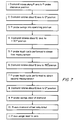
- Figure 7 is an additional process flow diagram providing a more detailed illustration of the zeroing process of the invention.
- Figure 8 is another process flow diagram illustrating the details of the probe contact cycle.
- the numeral 10 generally designates a one-station electro-mechanical internal grinding machine with a single grinding wheel spindle 12 on a compound slide assembly 14.
- the grinding machine 10 includes a conventional bed or base member 16 on which is operatively mounted a conventional workhead 18.
- the compound slide assembly 14 is also mounted on the base member 16 and includes a longitudinal or Z-axis slide 20 mounted on base 16 and a cross or X-axis slide 22 operatively mounted on Z-axis slide 20.
- the wheel spindle can be moved simultaneously in the Z-axis and X-axis directions by slides 20 and 22.
- the workhead 18 may be of any suitable conventional structure and includes a chucking fixture 30 for holding a workpiece.
- the chucking fixture 30 may be of the centerless type and rotated by a motor 33 and pulley 34 on the workhead 18.
- a grinding wheel 40 is operatively held in the spindle 12 which is rotated by motor 41.
- the grinding wheel 40 can be moved to and from the workpiece held in chucking fixture 30 and into contact with the workpiece; e.g., into contact with an inner bore, to grind the workpiece.
- the grinding wheel 40 is also movable by the Z-axis and X-axis slides 20 and 22 to and from the dresser apparatus 50 located laterally toward the side of the base member 16.
- the dresser 50 includes a support base 52 fixed in position on the base member so that the grinding wheel 40 is brought to and from the dresser apparatus 50 to effect dressing thereof. The dresser will be described in greater detail hereinbelow.
- FIG. 62 A block diagram of the control system employed to control movements of the Z-axis and X-axis slides 20 and 22 as well as pivoting of the dresser holder arm and translation of the dresser member is illustrated in Figure 2.
- the numeral 62 generally designates a control computer or data processor having a memory which is programmed to control all machine functions and interlocks. Such functions include lubrication status, safety interlocks, motor status and operation control station information.
- the control computer 62 may be any suitable digital computer or microprocessor.
- the control computer 62 has stored the positions and rates for all the axis moves for the various sequences which may include a grind cycle, dress cycle and so forth.
- the control computer 62 sends servo drive signals to the servo drive means 66 and 68 for controlling the servo motors 70, 72 with respect to the respective Z-axis and X-axis slides to cause the grinding wheel to move in the desired wheel contour path.
- the servo drive means 66, 68 take feedback from the tachometers 76, 78 respectively.
- the numerals 80, 82 designate either resolvers, encoders or "INDUCTOSYN" transducers and they provide feedback signals to the control computer 62 in closed servo loop manner, with the tachometers closing inner loops.
- Reference numerals 80 and 82 could also be laser interferometers or other linear displacement transducers, such as magnetic or optical scales.
- the Z-axis and X-axis slides 20, 22 are driven and controlled by the control system described above by a conventional ball screw or other screw means rotated by servo motors, 70, 72 as explained in U.S. Patent No. 4,419,612 issued December 6, 1983 of common assignee, the teachings of which are incorporated herein by reference.
- the operation of such a grinding machine 10 in the grinding mode under control of a control computer is described in detail in the aforementioned U.S. Patent No. 4,419,612.
- the Z-axis and X-axis slides 20, 22 are sequenced by the control system described hereinabove to convey the grinding wheel 40 to the dresser apparatus 50 located adjacent the side of the machine on base member 16.
- the dresser apparatus 50 includes a dresser housing 100 on dresser base 52 as illustrated in Figure 3. Mounted pivotably on housing 100 is a pivotal or rotatable dresser holder arm 102. Dresser arm 102 is pivotably mounted so that the dresser arm can be rotated angularly to dress or true a particular convex or concave radius onto a grinding wheel.
- the control system described above can be used to maintain orthogonality of the dresser to the tangent plane of the surface being dressed.
- the details of the orthogonal dressing operation are set forth in U.S. Patent No. 4,603,677 which is incorporated herein by reference.
- Control computer 62 also has input and stored therein control information to position the dresser carriage member 220 and dresser tip 103 at a desired position relative to pivot axis E for a particular dimension (radius) and shape of working surface on the grinding wheel.
- the dresser tip 103 is said to be diplaced along a P-axis slide by linear translation of the dresser carriage relative to the slide.
- the dresser tip 103 can be moved automatically by the control computer 62 in accordance with a stored dresser program correlated with a stored workpart program for effecting grinding of different radius defined surfaces on the same workpart or on different workparts. The operator of the grinding machine would not be required to manually reset the position of the dresser tip 103 as in the past.
- the radius setting motor 170 is a servo motor that includes a tachometer 259 and an encoder or resolver 260 as a dresser feedback position transducer interfacing with servo drive means 262 through control computer 62.
- Control computer 62 uses the stored dresser control information in combination with servo loop feedback from resolver 260 to control and to adjust the position of the dresser tip 103 on arm 102 relative to pivot axis E so as to dress the same or different grinding wheels with working surfaces defined by different radii.
- the dressed grinding wheel is of course used to grind the different radius defined surfaces on the same or different workparts.
- Servo motor 170, servo drive means 262 and resolver 260 can be of the commercially available type described above.
- a first set of multiple workparts to be successively ground with a certain radius and shape of grinding wheel can be ground followed by a second set of multiple workparts to be successively ground by a wheel with a different radius and/or shape.
- the dresser tip 103 would be automatically positioned in accordance with a dresser program in the computer control to dress the first wheel radius/shape for the first set of workparts and then repositioned to dress the second wheel radius/ shape for the second set of workparts and so on for other workparts to be ground. Additional details regarding structure and operation of the P-axis slide can be found in U.S. Patent No. 4,805,585.
- a probe 104 is employed to accurately measure the distance between the dresser tip 103 and an axis E about which the dresser rotates.
- the probe 104 is rotated by support arm 106 such that the probe 104 is centered along axis E.
- the support arm 106 is mounted on a bearing 108 and is driven by an hydraulic cylinder and rotary actuator 105 (not shown) that is instructed by the control computer to rotate between a first position within enclosure 110 to a second measuring position adjacent the dresser tip 103.
- the probe 104 generally comprises a probe stylus bar 112 having a known fixed length. As shown in Figures 4 and 5, at each end of the bar 112, a contact surface is provided that is suitable for contact by the dresser tip. Both the first and second contact surfaces are spherical in shape about the center of the bar 112. The radius of this sphere is therefore equal to half of the length of bar 112. Any small rotational misalignment of the bar 112 will not affect the measurement as a result of this geometry.
- the stylus bar 112 is mounted on a stylus extension member 114 which can rotate away from the longitudinal axis S of the probe 104.
- the extension member 114 is mounted in probe body 116 to permit rotational overtravel of the extension member 114 and the stylus bar 112 that is rigidly secured thereto.
- the probe body 116 contains a contact sensor that generates an electrical signal upon contact of the bar 112 with some external body, which for the present invention is the dresser tip 103.
- the probe body 116, sensor and stylus extension are commercially available from Renishaw Inc., 623 Cooper Count, Schaumburg, Illinois 60173.
- the stylus bar 112 is centered on the probe axis S in its non-displaced position.
- This axis S is preferably aligned with the E-axis, but may be offset 120 by a few thousandths of an inch from the center of the pivot axis E of the dresser apparatus.
- any Z-axis misalignment which might occur due to rotation of the probe so that the S-axis is not perfectly aligned with the Z-axis, will automatically be corrected as a result of the two point contact method.
- the use of two contact 0 measurements is preferably done 180 degrees apart to maximize accuracy. However, any angular displacement between 90 and 270 degrees can be used to provide the correction.
- the dresser tip 103 is first brought into position adjacent a first contact surface 122 of the stylus bar moved into contact therewith.
- the probe 104 generates a signal upon contact and delivers the signal to the computer. This contact signal identifies the precise position of the dresser tip in conjunction with the position feedback control system of the dresser slide described in greater detail above.
- the dresser tip 103 is then rotated 180 degrees about axis E and brought in contact with a second contact surface 124 of probe 104.
- a second contact signal is then generated to identify the second contact position of the dresser tip.
- the first and second contact positions are then averaged and the result compared with the radius of the bar 112 to provide the P-axis diamond offset. This diamond offset is used to provide the exact radial distance of the dresser tip to the axis E.
- the dressing profile data for a particular grinding surface is then corrected accordingly.
- FIGs 6, 7 and 8 are flow charts which illustrate the operation of the dresser P-probe re-zero cycle.
- Figure 6 illustrates an overview of the process.
- a dress compensation counter at Block A keeps track of dress compensation against the P-axis dresser and causes a re-zero cycle when this compenstation becomes greater than an operator programmed amount, "p-axis re-zero trip".
- p-axis re-zero trip an operator programmed amount
- Block B represents the P-probe re-zero cycle, which is illustrated in detail in the flow chart of Figure 7.
- the P-Probe re-zero cycle begins with the diamond moving along the P-axis to the P-Probe clearance position. The diamond then rotates about the E-axis to the zero degree position, as shown in Figure 5, that is orthogonal to the longitudinal axis of stylus bar 112 in this embodiment.
- the P-probe swings into its operating position and the diamond rotates about the E-axis to the first position.
- a first measurement of the diamond position along the P-axis is obtained by performing a P-probe touch cycle.
- Figure 8 shows a flow chart which illustrates the P-probe touch cycle.
- the diamond moves along the P-axis direction to hit the probe stylus bar 112 at the P-probe approach rate.
- the diamond then moves along the p-axis direction away from the P-probe at the P-probe backoff rate.
- the diamond resumes moving toward the first contact surface of bar 112 along the direction of the P-axis to touch the P-probe at the P-probe touch rate.
- the detected p-axis position of the diamond is stored in memory.
- the diamond moves along the P-axis to the P-probe clearance position to complete the P-probe touch cycle.
- Figure 7 illustrates the continuation of the P-probe re-zero cycle.
- the diamond is rotated 180 degrees about the E-axis to the second position.
- a second P-probe touch cycle is performed, as noted above, to obtain a second measurement of the diamond position.
- the diamond After making the second measurement, the diamond is rotated about the E-axis to the 0 degree position and the P-probe swings clear of the diamond.
- the P-axis diamond offset is calculated from the first and second measurements as set forth above. Finally, the P-axis usage is reset to zero.
- the calculated P-axis zero offset can be used to recalibrate the dresser.
- the dresser is then monitored by the dress compensation counter to determine when the next P-probe re-zero cycle should occur.
Landscapes
- Engineering & Computer Science (AREA)
- Human Computer Interaction (AREA)
- Manufacturing & Machinery (AREA)
- Physics & Mathematics (AREA)
- General Physics & Mathematics (AREA)
- Automation & Control Theory (AREA)
- Grinding-Machine Dressing And Accessory Apparatuses (AREA)
Abstract
Description
- Grinding machines having a wheel dresser with a diamond dresser carried on a pivotal holder arm have been used for dressing grinding wheels. The pivotal holder arm is pivotable about a substantially vertical axis to cause the diamond dresser to be moved in a circular or arcuate path against the grinding wheel to dress a circular path on the working face of the wheel. The diamond dresser is manually adjustable in position on the holder arm to vary the radius of the circular path traced by the dresser and thus the radius of the working surface dressed on the wheel.
- Orthogonal dressing of a grinding wheel by a diamond dresser has also been developed, the diamond dresser being mounted on a pivotal holder. Coarse adjustment of the diamond dresser relative to the pivot line or axis of the holder is effected manually by a set screw that slides a dresser support plate relative to the pivotal holder. Fine adjustment of the diamond dresser relative to the pivot line is provided by a manually turned threaded adjustment screw that deflects a plate carrying the diamond dresser. In this way, the radius of the circular path of the dresser can be varied.
- Alternatively, the rotary dresser wheel can be carried on a compound slide assembly that is controlled by an electronic control system. The dresser wheel moves along an axis relative to the grinding wheel under control of an automatic computer numerically controlled (CNC) system which controls movement of the grinding wheel and table during grinding operations. A need exists, however, to improve control of the dressing operation to provide more consistent dressing of grinding surfaces during the lifetime of each dresser.
- Devices that compensate for dresser wear are also known, see EP-A-0 281 835. In this case, a sensing element utilizes a single scanning pin to sense the shape of both a reference surface and the dresser tip surface. Data collected from each surface is compared and the degree of dresser tip wear is determined. Wear in excess of a threshold triggers adjustment in the dresser tool position.
- Another reference that teaches compensation for dresser wear is EP-A-O 341 968 which discloses an apparatus and a method according to the preambles of
claims - The apparatus and method of the present invention are characterised by the features of the characterising portions of
claims - The present invention relates to a radius dresser apparatus for dressing or truing a grinding wheel wherein a dresser member is carried on a pivotal support or holder arm and the dresser is adjustable in position on the pivotal holder arm to vary the position of the dresser member relative to the pivot axis about which the holder arm rotates. A contact probe having a first contact surface, a second contact surface and a contact sensor such that the contact sensor generates a second electrical signal upon contact at the first contact surface or the second contact surface by the dresser and, whose structure and operation are described in detail below, is mounted on the dresser apparatus that can be positioned about the pivot axis and used to accurately measure the position of the dresser tip relative to the pivot axis.
- Adjustment of the dresser position is effected by an actuator on the pivotal holder arm controlled by a control computer using a stored dresser program in combination with dresser feedback position signals. In connection with the dressing of a grinding wheel, the dresser program is correlated with workparts to be ground with different radius-defined surfaces so as to automatically dress one or more grinding wheels with different radius-defined working surfaces for grinding the workparts.
- In a typical working embodiment of the invention, the dresser member is disposed on a "P-axis" slide that is moveable on the pivotable holder arm. The slide is driven in turn by a radius setting motor, such as a servomotor, on the grinding machine and under control of the machine CNC unit. The CNC unit uses a stored dresser program and closed loop dresser position feedback signals from a position transducer associated with the radius setting motor.
- After a number of dressing cycles the dresser tip is typically worn down so that the distance between the dresser tip, and the pivot axis of the dresser has altered. The contact probe is used to periodically measure the position of the dresser to correct for any change in the position of the dresser tip due to wear, or any other reason.
- The probe is preferably mounted by a rotatable arm onto the dresser housing and can be actuated by an hydraulic unit that is electrically controlled by the computer or microprocessor of the CNC unit. The probe is rotated from a storage position to a measuring position at the direction of the operator or by a stored program. The probe has first and second contact surfaces which the dresser contacts and thereby generates a contact signal which indicates at what position the dresser is located upon contact with the probe. After measuring the first contact the P-axis is rotated 180 degrees about the pivot axis to be brought into alignment with the second contact surface and the dresser is again linearly translated along the slide until the dresser contacts the opposite side of the probe on the second contact surface. The two recorded contact positions of the dresser can be processed or averaged to accurately calculate the position of the dresser tip relative to the pivot axis.
- Figure 1 schematically illustrates a preferred embodiment of a grinding machine that utilizes the present invention.
- Figure 2 is a schematic illustration of a control system for a grinding machine employing the dresser positioning of the invention.
- Figure 3 is a side elevation of a preferred embodiment of the positioning mechanism for the dresser.
- Figure 4 is a side view of a preferred embodiment of a contact probe to be used in accordance with the invention.
- Figure 5 is a detailed top view illustrating a preferred method of measuring the position of a dresser relative to a pivot axis.
- Figure 6 is a process flow diagram illustrating a method of measuring the dresser position.
- Figure 7 is an additional process flow diagram providing a more detailed illustration of the zeroing process of the invention.
- Figure 8 is another process flow diagram illustrating the details of the probe contact cycle.
- Referring to Figure 1, the
numeral 10 generally designates a one-station electro-mechanical internal grinding machine with a singlegrinding wheel spindle 12 on acompound slide assembly 14. - The
grinding machine 10 includes a conventional bed orbase member 16 on which is operatively mounted aconventional workhead 18. Thecompound slide assembly 14 is also mounted on thebase member 16 and includes a longitudinal or Z-axis slide 20 mounted onbase 16 and a cross orX-axis slide 22 operatively mounted on Z-axis slide 20. The wheel spindle can be moved simultaneously in the Z-axis and X-axis directions byslides - The
workhead 18 may be of any suitable conventional structure and includes achucking fixture 30 for holding a workpiece. Thechucking fixture 30 may be of the centerless type and rotated by amotor 33 andpulley 34 on theworkhead 18. - As shown in Figure 1, a
grinding wheel 40 is operatively held in thespindle 12 which is rotated bymotor 41. By movement of the Z-axis and X-axis slides 20 and 22, thegrinding wheel 40 can be moved to and from the workpiece held inchucking fixture 30 and into contact with the workpiece; e.g., into contact with an inner bore, to grind the workpiece. - The
grinding wheel 40 is also movable by the Z-axis andX-axis slides dresser apparatus 50 located laterally toward the side of thebase member 16. In the embodiment shown in Figure 1, thedresser 50 includes asupport base 52 fixed in position on the base member so that the grindingwheel 40 is brought to and from thedresser apparatus 50 to effect dressing thereof. The dresser will be described in greater detail hereinbelow. - A block diagram of the control system employed to control movements of the Z-axis and
X-axis slides numeral 62 generally designates a control computer or data processor having a memory which is programmed to control all machine functions and interlocks. Such functions include lubrication status, safety interlocks, motor status and operation control station information. Thecontrol computer 62 may be any suitable digital computer or microprocessor. - The
control computer 62 has stored the positions and rates for all the axis moves for the various sequences which may include a grind cycle, dress cycle and so forth. Thecontrol computer 62 sends servo drive signals to the servo drive means 66 and 68 for controlling theservo motors 70, 72 with respect to the respective Z-axis and X-axis slides to cause the grinding wheel to move in the desired wheel contour path. The servo drive means 66, 68 take feedback from thetachometers numerals control computer 62 in closed servo loop manner, with the tachometers closing inner loops.Reference numerals - Further details regarding the computer and other control, drive and feedback system components are set forth in U.S. Patent No. 4,805,585 that is incorporated herein by reference.
- The Z-axis and X-axis slides 20, 22 are driven and controlled by the control system described above by a conventional ball screw or other screw means rotated by servo motors, 70, 72 as explained in U.S. Patent No. 4,419,612 issued December 6, 1983 of common assignee, the teachings of which are incorporated herein by reference. The operation of such a grinding
machine 10 in the grinding mode under control of a control computer is described in detail in the aforementioned U.S. Patent No. 4,419,612. - In the wheel dressing mode, the Z-axis and X-axis slides 20, 22 are sequenced by the control system described hereinabove to convey the
grinding wheel 40 to thedresser apparatus 50 located adjacent the side of the machine onbase member 16. - The
dresser apparatus 50 includes adresser housing 100 ondresser base 52 as illustrated in Figure 3. Mounted pivotably onhousing 100 is a pivotal or rotatabledresser holder arm 102.Dresser arm 102 is pivotably mounted so that the dresser arm can be rotated angularly to dress or true a particular convex or concave radius onto a grinding wheel. The control system described above can be used to maintain orthogonality of the dresser to the tangent plane of the surface being dressed. The details of the orthogonal dressing operation are set forth in U.S. Patent No. 4,603,677 which is incorporated herein by reference. -
Control computer 62 also has input and stored therein control information to position thedresser carriage member 220 anddresser tip 103 at a desired position relative to pivot axis E for a particular dimension (radius) and shape of working surface on the grinding wheel. Thedresser tip 103 is said to be diplaced along a P-axis slide by linear translation of the dresser carriage relative to the slide. Thedresser tip 103 can be moved automatically by thecontrol computer 62 in accordance with a stored dresser program correlated with a stored workpart program for effecting grinding of different radius defined surfaces on the same workpart or on different workparts. The operator of the grinding machine would not be required to manually reset the position of thedresser tip 103 as in the past. - To this end, the
radius setting motor 170 is a servo motor that includes atachometer 259 and an encoder orresolver 260 as a dresser feedback position transducer interfacing with servo drive means 262 throughcontrol computer 62.Control computer 62 uses the stored dresser control information in combination with servo loop feedback fromresolver 260 to control and to adjust the position of thedresser tip 103 onarm 102 relative to pivot axis E so as to dress the same or different grinding wheels with working surfaces defined by different radii. The dressed grinding wheel is of course used to grind the different radius defined surfaces on the same or different workparts.Servo motor 170, servo drive means 262 andresolver 260 can be of the commercially available type described above. - With computer control of the
radius setting motor 170 and thus of the position ofdresser tip 103 relative to the pivot axis E, a first set of multiple workparts to be successively ground with a certain radius and shape of grinding wheel can be ground followed by a second set of multiple workparts to be successively ground by a wheel with a different radius and/or shape. Thedresser tip 103 would be automatically positioned in accordance with a dresser program in the computer control to dress the first wheel radius/shape for the first set of workparts and then repositioned to dress the second wheel radius/ shape for the second set of workparts and so on for other workparts to be ground. Additional details regarding structure and operation of the P-axis slide can be found in U.S. Patent No. 4,805,585. - To maintain a proper dressing operation during the the lifetime of the
diamond tip 103 of the dresser it is advisable to determine the precise relationship between thedresser tip 103 and the surface being dressed. In a preferred embodiment of the present invention aprobe 104 is employed to accurately measure the distance between thedresser tip 103 and an axis E about which the dresser rotates. Theprobe 104 is rotated bysupport arm 106 such that theprobe 104 is centered along axis E. Thesupport arm 106 is mounted on abearing 108 and is driven by an hydraulic cylinder and rotary actuator 105 (not shown) that is instructed by the control computer to rotate between a first position withinenclosure 110 to a second measuring position adjacent thedresser tip 103. - The
probe 104 generally comprises aprobe stylus bar 112 having a known fixed length. As shown in Figures 4 and 5, at each end of thebar 112, a contact surface is provided that is suitable for contact by the dresser tip. Both the first and second contact surfaces are spherical in shape about the center of thebar 112. The radius of this sphere is therefore equal to half of the length ofbar 112. Any small rotational misalignment of thebar 112 will not affect the measurement as a result of this geometry. Thestylus bar 112 is mounted on astylus extension member 114 which can rotate away from the longitudinal axis S of theprobe 104. Theextension member 114 is mounted inprobe body 116 to permit rotational overtravel of theextension member 114 and thestylus bar 112 that is rigidly secured thereto. Theprobe body 116 contains a contact sensor that generates an electrical signal upon contact of thebar 112 with some external body, which for the present invention is thedresser tip 103. - The
probe body 116, sensor and stylus extension are commercially available from Renishaw Inc., 623 Cooper Count, Schaumburg, Illinois 60173. - Operation of the probe positioning system is more clearly illustrated in connection with Figure 5. The
stylus bar 112 is centered on the probe axis S in its non-displaced position. This axis S is preferably aligned with the E-axis, but may be offset 120 by a few thousandths of an inch from the center of the pivot axis E of the dresser apparatus. However any Z-axis misalignment, which might occur due to rotation of the probe so that the S-axis is not perfectly aligned with the Z-axis, will automatically be corrected as a result of the two point contact method. The use of two contact 0 measurements is preferably done 180 degrees apart to maximize accuracy. However, any angular displacement between 90 and 270 degrees can be used to provide the correction. - The
dresser tip 103 is first brought into position adjacent afirst contact surface 122 of the stylus bar moved into contact therewith. Theprobe 104 generates a signal upon contact and delivers the signal to the computer. This contact signal identifies the precise position of the dresser tip in conjunction with the position feedback control system of the dresser slide described in greater detail above. - The
dresser tip 103 is then rotated 180 degrees about axis E and brought in contact with asecond contact surface 124 ofprobe 104. A second contact signal is then generated to identify the second contact position of the dresser tip. The first and second contact positions are then averaged and the result compared with the radius of thebar 112 to provide the P-axis diamond offset. This diamond offset is used to provide the exact radial distance of the dresser tip to the axis E. The dressing profile data for a particular grinding surface is then corrected accordingly. - Figures 6, 7 and 8 are flow charts which illustrate the operation of the dresser P-probe re-zero cycle. Figure 6 illustrates an overview of the process. A dress compensation counter at Block A keeps track of dress compensation against the P-axis dresser and causes a re-zero cycle when this compenstation becomes greater than an operator programmed amount, "p-axis re-zero trip". Thus, after the operator initiates the re-zero cycle, monitoring is repeated each time the trip threshold is exceeded.
- Block B represents the P-probe re-zero cycle, which is illustrated in detail in the flow chart of Figure 7. The P-Probe re-zero cycle begins with the diamond moving along the P-axis to the P-Probe clearance position. The diamond then rotates about the E-axis to the zero degree position, as shown in Figure 5, that is orthogonal to the longitudinal axis of
stylus bar 112 in this embodiment. The P-probe swings into its operating position and the diamond rotates about the E-axis to the first position. A first measurement of the diamond position along the P-axis is obtained by performing a P-probe touch cycle. - Figure 8 shows a flow chart which illustrates the P-probe touch cycle. Initially, the diamond moves along the P-axis direction to hit the
probe stylus bar 112 at the P-probe approach rate. The diamond then moves along the p-axis direction away from the P-probe at the P-probe backoff rate. The diamond resumes moving toward the first contact surface ofbar 112 along the direction of the P-axis to touch the P-probe at the P-probe touch rate. The detected p-axis position of the diamond is stored in memory. Finally, the diamond moves along the P-axis to the P-probe clearance position to complete the P-probe touch cycle. - Figure 7 illustrates the continuation of the P-probe re-zero cycle. After making the first measurement, the diamond is rotated 180 degrees about the E-axis to the second position. At this second measurement position, a second P-probe touch cycle is performed, as noted above, to obtain a second measurement of the diamond position.
- After making the second measurement, the diamond is rotated about the E-axis to the 0 degree position and the P-probe swings clear of the diamond. The P-axis diamond offset is calculated from the first and second measurements as set forth above. Finally, the P-axis usage is reset to zero.
- Returning to Figure 6, it can be seen that the calculated P-axis zero offset can be used to recalibrate the dresser. The dresser is then monitored by the dress compensation counter to determine when the next P-probe re-zero cycle should occur.
Claims (10)
- A dresser positioning system for a computer numerically controlled grinding machine (10) comprising:a dresser (103) mounted on a dresser slide, the dresser being linearly moveable relative to the dresser slide and rotatable about a pivot axis (E);a position sensor (260) to measure a position of the dresser relative to the dresser slide and to generate a first electrical signal representative of the dresser slide position; characterized in that:the dresser is rotatable about a pivot axis (E); and in that the system further comprises :a probe (104) having a first contact surface (122), a second contact surface (124), and a contact sensor such that the contact sensor generates a second electrical signal upon contact at the first contact surface or the second contact surface by the dresser; anda data processor (62) electrically connected to the position sensor and the contact sensor such that the data processor receives the first slide position electrical signal and the second contact electrical signal, the data processor having a memory in which to store position data representative of the dresser position when the dresser contacts the first or second contact surfaces of the probe.
- The dresser positioning system of Claim 1 wherein the probe (104) is moveably mounted onto a dresser housing (100) such that the probe can be positioned in a storage position and moved into a measuring position adjacent the dresser and including, optionally,
a support arm (106) on which the probe (104) is mounted and secured to the housing (100), the support arm being rotated relative to the housing by a motor and in which, further optionally,
wherein, in the measuring position, a probe axis (S) is located substantially along the pivot axis (E). - The dresser positioning system of Claim 1 wherein the probe (104) comprises a displaceable member (112) such that the first contact surface (122) is on a side of the member opposite the second contact surface (124).
- The dresser positioning system of Claim 1 further comprising either :A) a grinding wheel (40) mounted on a compound slide assembly (14);the dresser (103) being linearly moveable relative to the dresser slide and rotatable about a pivot axis (E) such that the dresser can be moved between a dressing position adjacent the grinding wheel and a probe (104) measuring position;the probe positionable adjacent to the dresser in the probe measuring position; anda servo drive system (170, 259, 260, 262) electrically connected to the data processor (62) to control movement of the dresser on the dresser slide and about the pivot axis; or further comprising:B) a second position sensor for measuring an angular position of the dresser (103) and for generating a third electrical signal representative of the angular position of the dresser and wherein:the dresser is linearly moveable in a radial direction with respect to the pivot axis (E) and the position sensor (260) measures the radial position of the dresser relative to the dresser slide;the data processor (62) is electrically connected to the second position sensor and receives the third electrical signal; andthe memory stores dresser radial and angular position data.
- A method for adjusting the dressing of a working surface of a grinding wheel (40) comprising:adjustably mounting a dresser member (103) on a pivot arm (102);positioning a probe (104) and the dresser member such that the dresser member is in contact with the probe at a first position and generating a first position electrical signal to identify the position of the dresser member upon contact with the probe;storing said first position signal identifying the first contact position of the dresser member; characterized in that:the pivot arm (102) has a pivot axis (E) about which the dresser member can rotate ; and in that the method further comprises :positioning said dresser member at a second position such that the dresser member is in contact with the probe and generating a second position electrical signal to identify the position of the dresser member upon contact with the probe;storing said second position signal of the dresser member;determining the dresser member position relative to the pivot axis using the first and second position electrical signals; andadjusting the dressing of the working surface from the determined dresser member positions, the determining step optionally further comprising averaging the first and second position signals.
- The method of Claim 5 wherein the first position comprises a first contact surface (122) of the probe (104) and the second position comprises a second contact surface (124) that is located on the probe on a side opposite the first contact surface.
- The method of Claim 6 wherein the dresser member (103) is rotated about the pivot axis (E) from the first position to the second position, and optionally arranged to be rotated through an angle of about 180 degrees from the first position to the second position.
- The method of any one of claims 5 to 7 further comprising providing A): a data processor (62) having a memory in which to store the first and second position signals and to determine the dresser member position relative to the pivot axis (E) and/or B):
further comprising providing a grinding wheel (40) on a compound slide assembly (14) and dressing the grinding wheel with the dresser member. - The method of Claim 8 wherein part B further comprises adjusting a position of the dresser member (103) relative to the grinding wheel (40) from the determined position of the dresser member relative to the pivot axis (E).
- The method of any one of Claims 5 to 9 further comprising providing a slide assembly on which the dresser member (103) is mounted and/or further comprising:sensing the angular position of the dresser member (103) about the pivot axis (E); andsensing the radial position of the dresser member (103) with respect to the pivot axis (E).
Applications Claiming Priority (3)
| Application Number | Priority Date | Filing Date | Title |
|---|---|---|---|
| US07/685,227 US5138799A (en) | 1991-04-12 | 1991-04-12 | Probe positioning mechanism for a radius dresser |
| US685227 | 1991-04-12 | ||
| PCT/US1992/002942 WO1992018918A1 (en) | 1991-04-12 | 1992-04-10 | Probe positioning mechanism for a radius dresser |
Publications (2)
| Publication Number | Publication Date |
|---|---|
| EP0579723A1 EP0579723A1 (en) | 1994-01-26 |
| EP0579723B1 true EP0579723B1 (en) | 1996-11-06 |
Family
ID=24751268
Family Applications (1)
| Application Number | Title | Priority Date | Filing Date |
|---|---|---|---|
| EP92909751A Expired - Lifetime EP0579723B1 (en) | 1991-04-12 | 1992-04-10 | Probe positioning mechanism for a radius dresser |
Country Status (4)
| Country | Link |
|---|---|
| US (1) | US5138799A (en) |
| EP (1) | EP0579723B1 (en) |
| DE (1) | DE69215083T2 (en) |
| WO (1) | WO1992018918A1 (en) |
Families Citing this family (7)
| Publication number | Priority date | Publication date | Assignee | Title |
|---|---|---|---|---|
| CA2082790A1 (en) * | 1991-12-02 | 1993-06-03 | R. David Hemmerle | Automated maintenance system for computer numerically controlled machines |
| US5538460A (en) * | 1992-01-16 | 1996-07-23 | System Seiko Co., Ltd. | Apparatus for grinding hard disk substrates |
| US5377454A (en) * | 1992-05-01 | 1995-01-03 | The Gleason Works | Method of truing and angling cutter blades by sharpening |
| ES2056701T3 (en) * | 1992-12-23 | 1994-10-01 | Voumard Machines Co Sa | SINGLE MOTOR DRIVING DEVICE FOR AVERAGE MOVER WITH ANGULAR AND LONGITUDINAL MOVEMENT. |
| US5456627A (en) * | 1993-12-20 | 1995-10-10 | Westech Systems, Inc. | Conditioner for a polishing pad and method therefor |
| US20040185760A1 (en) * | 2003-03-19 | 2004-09-23 | James Weatherly | Shaping apparatus for saw sharpening wheel |
| JP6497108B2 (en) * | 2015-02-16 | 2019-04-10 | 株式会社ジェイテクト | Control system |
Family Cites Families (21)
| Publication number | Priority date | Publication date | Assignee | Title |
|---|---|---|---|---|
| US2469365A (en) * | 1945-02-23 | 1949-05-10 | Oscar M Braaten | Tool for dressing grinding wheels |
| US2446833A (en) * | 1945-07-14 | 1948-08-10 | Vinco Corp | Apparatus for producing controlled relative motion between tools and workpieces |
| US2907315A (en) * | 1958-08-19 | 1959-10-06 | Norton Co | Truing apparatus |
| GB1295282A (en) * | 1969-02-11 | 1972-11-08 | ||
| US3897659A (en) * | 1974-08-30 | 1975-08-05 | Us Energy | Ultrasonic-acoustic grinding wheel setting station for automatic numerically-controlled machines |
| US4023310A (en) * | 1975-12-29 | 1977-05-17 | Bryant Grinder Corporation | Interform grinding machine |
| US4229909A (en) * | 1979-03-22 | 1980-10-28 | The United States Of America As Represented By The United States Department Of Energy | Tool grinding machine |
| US4419612A (en) * | 1980-05-22 | 1983-12-06 | Ex-Cell-O Corporation | Single workhead electro-mechanical internal grinding machine with grinding spindle directly on cross slide |
| JPS58121655U (en) * | 1982-02-15 | 1983-08-18 | 豊田工機株式会社 | Grinding wheel truing device |
| BE895347A (en) * | 1982-12-14 | 1983-06-14 | Rech S Et De Dev Ind S A Soc D | APPARATUS FOR PROFILING AN ABRASIVE GRINDER |
| US4559919A (en) * | 1983-12-15 | 1985-12-24 | Anthony Kushigian | Grinding wheel profiler |
| DE3426548A1 (en) * | 1984-07-19 | 1986-01-30 | Burkhardt & Weber GmbH & Co KG, 7410 Reutlingen | Machine tool with a computer-aided control system as well as a tool holder and a measuring unit for a machine tool |
| US4603677A (en) * | 1984-08-29 | 1986-08-05 | Gile Richard H | Orthogonal dressing of grinding wheels |
| CH668211A5 (en) * | 1985-11-25 | 1988-12-15 | Tschudin Werkzeugmasch | METHOD FOR ZERO SETTING A ROUND GRINDING MACHINE AND MEANS FOR IMPLEMENTING THE METHOD. |
| US4704825A (en) * | 1986-09-02 | 1987-11-10 | Moore Special Tool Co., Inc. | Method for automatically sizing a ground surface on a workpiece |
| DE3707775C2 (en) * | 1987-03-11 | 1996-03-07 | Jung Gmbh K | CNC-controlled grinding machine with a dressing device |
| US5003730A (en) * | 1987-08-19 | 1991-04-02 | Bryant Grinder Corporation | Radius dressing apparatus |
| DE3731006A1 (en) * | 1987-09-16 | 1989-03-30 | Fortuna Werke Maschf Ag | GRINDING MACHINE |
| JPH01109071A (en) * | 1987-10-22 | 1989-04-26 | Toyoda Mach Works Ltd | Truing device for grinding wheel |
| US5025592A (en) * | 1988-05-09 | 1991-06-25 | Brother Kogyo Kabushiki Kaisha | Machine tool having workpiece machining dimension and tool length measuring functions |
| JP2637488B2 (en) * | 1988-07-28 | 1997-08-06 | 豊田工機株式会社 | Numerically controlled grinding machine |
-
1991
- 1991-04-12 US US07/685,227 patent/US5138799A/en not_active Expired - Fee Related
-
1992
- 1992-04-10 EP EP92909751A patent/EP0579723B1/en not_active Expired - Lifetime
- 1992-04-10 WO PCT/US1992/002942 patent/WO1992018918A1/en not_active Ceased
- 1992-04-10 DE DE69215083T patent/DE69215083T2/en not_active Expired - Fee Related
Also Published As
| Publication number | Publication date |
|---|---|
| EP0579723A1 (en) | 1994-01-26 |
| DE69215083D1 (en) | 1996-12-12 |
| WO1992018918A1 (en) | 1992-10-29 |
| US5138799A (en) | 1992-08-18 |
| DE69215083T2 (en) | 1997-05-28 |
Similar Documents
| Publication | Publication Date | Title |
|---|---|---|
| CA2206718C (en) | Multi-functional measurement system | |
| US4562392A (en) | Stylus type touch probe system | |
| KR950005873B1 (en) | Numerically controlled machine tool | |
| CA2316847A1 (en) | Precision high speed turning machine | |
| GB2163872A (en) | Datum reference for machine tool | |
| US6038489A (en) | Machine tools | |
| CA2082790A1 (en) | Automated maintenance system for computer numerically controlled machines | |
| GB2057133A (en) | Gear tooth flank testing machine | |
| US5138799A (en) | Probe positioning mechanism for a radius dresser | |
| JP2590531B2 (en) | Method and apparatus for measuring in-process effective diameter of screw shaft | |
| US20040215414A1 (en) | Method and apparatus for measuring and machining workpieces | |
| EP0371967B1 (en) | Apparatus for sensing a lens blank and a machine including such apparatus | |
| GB2152409A (en) | Apparatus for monitoring the diameters and axial positions of workpieces in machine tools | |
| JPH10156692A (en) | Cam grinder | |
| US3886666A (en) | Apparatus for measuring tool path accuracy | |
| JP3786327B2 (en) | Touch probe support mechanism on the grinding wheel head | |
| JPH0780122B2 (en) | Computer numerical control type grinding machine and dresser tool correction determination method. | |
| JP2767852B2 (en) | Grinding machine with tool length setting function | |
| JPS6244375A (en) | NC grindstone forming device | |
| JP2565968B2 (en) | Forming method of grinding wheel in thread groove grinding | |
| JPS63232968A (en) | grinding equipment | |
| JP2001179621A (en) | Moving amount measuring device and grinding device | |
| JPS6119907Y2 (en) | ||
| JPH054166A (en) | Numerical controlier for grinder | |
| JPS63232965A (en) | Workpiece grinding method |
Legal Events
| Date | Code | Title | Description |
|---|---|---|---|
| PUAI | Public reference made under article 153(3) epc to a published international application that has entered the european phase |
Free format text: ORIGINAL CODE: 0009012 |
|
| 17P | Request for examination filed |
Effective date: 19931103 |
|
| AK | Designated contracting states |
Kind code of ref document: A1 Designated state(s): CH DE IT LI |
|
| 17Q | First examination report despatched |
Effective date: 19950420 |
|
| GRAG | Despatch of communication of intention to grant |
Free format text: ORIGINAL CODE: EPIDOS AGRA |
|
| GRAH | Despatch of communication of intention to grant a patent |
Free format text: ORIGINAL CODE: EPIDOS IGRA |
|
| GRAH | Despatch of communication of intention to grant a patent |
Free format text: ORIGINAL CODE: EPIDOS IGRA |
|
| GRAA | (expected) grant |
Free format text: ORIGINAL CODE: 0009210 |
|
| ITF | It: translation for a ep patent filed | ||
| AK | Designated contracting states |
Kind code of ref document: B1 Designated state(s): CH DE IT LI |
|
| REF | Corresponds to: |
Ref document number: 69215083 Country of ref document: DE Date of ref document: 19961212 |
|
| REG | Reference to a national code |
Ref country code: CH Ref legal event code: NV Representative=s name: PATENTANWAELTE SCHAAD, BALASS, MENZL & PARTNER AG |
|
| PLBE | No opposition filed within time limit |
Free format text: ORIGINAL CODE: 0009261 |
|
| 26N | No opposition filed | ||
| PGFP | Annual fee paid to national office [announced via postgrant information from national office to epo] |
Ref country code: CH Payment date: 20030424 Year of fee payment: 12 |
|
| PGFP | Annual fee paid to national office [announced via postgrant information from national office to epo] |
Ref country code: DE Payment date: 20030618 Year of fee payment: 12 |
|
| PG25 | Lapsed in a contracting state [announced via postgrant information from national office to epo] |
Ref country code: LI Free format text: LAPSE BECAUSE OF NON-PAYMENT OF DUE FEES Effective date: 20040430 Ref country code: CH Free format text: LAPSE BECAUSE OF NON-PAYMENT OF DUE FEES Effective date: 20040430 |
|
| PG25 | Lapsed in a contracting state [announced via postgrant information from national office to epo] |
Ref country code: DE Free format text: LAPSE BECAUSE OF NON-PAYMENT OF DUE FEES Effective date: 20041103 |
|
| REG | Reference to a national code |
Ref country code: CH Ref legal event code: PL |
|
| PG25 | Lapsed in a contracting state [announced via postgrant information from national office to epo] |
Ref country code: IT Free format text: LAPSE BECAUSE OF NON-PAYMENT OF DUE FEES;WARNING: LAPSES OF ITALIAN PATENTS WITH EFFECTIVE DATE BEFORE 2007 MAY HAVE OCCURRED AT ANY TIME BEFORE 2007. THE CORRECT EFFECTIVE DATE MAY BE DIFFERENT FROM THE ONE RECORDED. Effective date: 20050410 |