EP0578975A1 - Method and apparatus for predicting effect of yarn defects on the appearance of textiles or fabrics - Google Patents
Method and apparatus for predicting effect of yarn defects on the appearance of textiles or fabrics Download PDFInfo
- Publication number
- EP0578975A1 EP0578975A1 EP93109438A EP93109438A EP0578975A1 EP 0578975 A1 EP0578975 A1 EP 0578975A1 EP 93109438 A EP93109438 A EP 93109438A EP 93109438 A EP93109438 A EP 93109438A EP 0578975 A1 EP0578975 A1 EP 0578975A1
- Authority
- EP
- European Patent Office
- Prior art keywords
- yarn
- parameters
- pixels
- values
- conversion
- Prior art date
- Legal status (The legal status is an assumption and is not a legal conclusion. Google has not performed a legal analysis and makes no representation as to the accuracy of the status listed.)
- Granted
Links
- 239000004744 fabric Substances 0.000 title claims abstract description 18
- 230000007547 defect Effects 0.000 title claims abstract description 9
- 230000000694 effects Effects 0.000 title claims abstract description 7
- 238000000034 method Methods 0.000 title claims description 17
- 239000004753 textile Substances 0.000 title description 6
- 238000004088 simulation Methods 0.000 claims abstract description 16
- 238000010586 diagram Methods 0.000 claims description 18
- 238000012360 testing method Methods 0.000 claims description 16
- 206010020112 Hirsutism Diseases 0.000 claims description 12
- 238000006243 chemical reaction Methods 0.000 claims description 9
- 238000005259 measurement Methods 0.000 claims description 4
- 238000004040 coloring Methods 0.000 claims description 3
- 238000012545 processing Methods 0.000 claims description 3
- 238000009877 rendering Methods 0.000 claims description 2
- 238000004519 manufacturing process Methods 0.000 abstract description 3
- 239000002759 woven fabric Substances 0.000 abstract 1
- 239000000523 sample Substances 0.000 description 11
- 230000000737 periodic effect Effects 0.000 description 10
- 238000004364 calculation method Methods 0.000 description 6
- 238000011156 evaluation Methods 0.000 description 5
- 239000000463 material Substances 0.000 description 5
- 101100116570 Caenorhabditis elegans cup-2 gene Proteins 0.000 description 1
- 101100116572 Drosophila melanogaster Der-1 gene Proteins 0.000 description 1
- TZCXTZWJZNENPQ-UHFFFAOYSA-L barium sulfate Chemical compound [Ba+2].[O-]S([O-])(=O)=O TZCXTZWJZNENPQ-UHFFFAOYSA-L 0.000 description 1
- 238000005516 engineering process Methods 0.000 description 1
- 239000000835 fiber Substances 0.000 description 1
- 239000002184 metal Substances 0.000 description 1
- 229910052751 metal Inorganic materials 0.000 description 1
- 238000001228 spectrum Methods 0.000 description 1
Images

Classifications
-
- G—PHYSICS
- G01—MEASURING; TESTING
- G01N—INVESTIGATING OR ANALYSING MATERIALS BY DETERMINING THEIR CHEMICAL OR PHYSICAL PROPERTIES
- G01N33/00—Investigating or analysing materials by specific methods not covered by groups G01N1/00 - G01N31/00
- G01N33/36—Textiles
- G01N33/365—Filiform textiles, e.g. yarns
-
- B—PERFORMING OPERATIONS; TRANSPORTING
- B65—CONVEYING; PACKING; STORING; HANDLING THIN OR FILAMENTARY MATERIAL
- B65H—HANDLING THIN OR FILAMENTARY MATERIAL, e.g. SHEETS, WEBS, CABLES
- B65H63/00—Warning or safety devices, e.g. automatic fault detectors, stop-motions ; Quality control of the package
-
- D—TEXTILES; PAPER
- D01—NATURAL OR MAN-MADE THREADS OR FIBRES; SPINNING
- D01H—SPINNING OR TWISTING
- D01H13/00—Other common constructional features, details or accessories
- D01H13/32—Counting, measuring, recording or registering devices
-
- D—TEXTILES; PAPER
- D04—BRAIDING; LACE-MAKING; KNITTING; TRIMMINGS; NON-WOVEN FABRICS
- D04B—KNITTING
- D04B37/00—Auxiliary apparatus or devices for use with knitting machines
-
- B—PERFORMING OPERATIONS; TRANSPORTING
- B65—CONVEYING; PACKING; STORING; HANDLING THIN OR FILAMENTARY MATERIAL
- B65H—HANDLING THIN OR FILAMENTARY MATERIAL, e.g. SHEETS, WEBS, CABLES
- B65H2701/00—Handled material; Storage means
- B65H2701/30—Handled filamentary material
- B65H2701/31—Textiles threads or artificial strands of filaments
Definitions
- the present invention relates to a method and a device for assessing the effect of yarn defects on woven or knitted fabrics made from the yarn in question by simulation of the product image.
- the device according to the invention is characterized by a measuring element for determining parameters related to the volume and / or the surface of the yarn, by a computer for converting the parameters mentioned into gray or color values, by means for assigning the gray or color values to pixels, by a screen and / or a printer and by control means for displaying the pixels on the screen and / or the printer for the purpose of simulating a woven or knitted fabric made from the examined yarn.
- the display boards are produced electronically, with the use of a uniformity tester, such as the USTER TESTER (USTER - registered trademark of Zellweger Uster AG), as a measuring device for examining the parameters mentioned, the electronic display boards from the commonly produced data be calculated.
- a uniformity tester such as the USTER TESTER (USTER - registered trademark of Zellweger Uster AG)
- USTER TESTER USTER - registered trademark of Zellweger Uster AG
- the uniformity and / or hairiness of a yarn sample is examined and in the form of a diagram, a wavelength spectrum and other graphical representations of the fluctuations in the measured parameters are displayed on a screen and / or a printer.
- the uniformity and the hairiness there are two parameters which are essential for the later product image and which can be processed with a relatively low software effort for the simulation of the display boards.
- the test system shown in FIG. 1 is the USTER TESTER from Zellweger Uster AG, which is used to determine material and quality parameters of textile test material, such as yarns. These parameters are, for example, fluctuations in mass, hairiness or structure (twist) of the yarn examined (see, for example, CH-A-671 105, EP-A-0 249 741, US-A-5 030 841), errors in these parameters being undesirable Impact on the finished textile product.
- the test system consists in a known manner of the actual test device 1, an evaluation and operating unit 2 and a printer 3.
- the test device 1 is provided with one or more measuring modules 4 which have measuring elements for the parameters to be examined.
- the test material or yarn designated by reference number 5 is transported through the measuring elements, which continuously measure the mass, hairiness and / or structure and convert them into electrical signals.
- the tested yarn 5 is suctioned off after the measurement.
- the signal and data processing and the functional control of the test system take place.
- Variables, measurement conditions and the desired representation of the results are entered via a keyboard 6, a screen 7 and control keys 8, and the measurement process and results appear on the screen 7 in numerical and graphic form.
- the printer 3 also serves to output measured values and graphic representations and in particular also to output complete test reports.
- FIG. 2 shows the fluctuations of the examined parameters over the length of the test material. If, for example, the hairiness is examined, then this is defined as the total length of the fibers protruding from the package within a certain measuring field length. The hairiness of a yarn is then the mean value formed over the entire test length.
- the diagram now shows the fluctuations of the examined parameter by an average value M, which corresponds to a normalized value of the signal representing the yarn cross section.
- the scatter or standard deviation can be calculated from these fluctuations, which are given in percentages when the mass fluctuations are examined and in absolute values when the hairiness is measured.
- Period errors have a certain wavelength and are easy to detect using the wavelength spectrogram, with chimneys occurring in the spectrogram indicating an error.
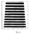
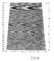
- 3 shows the spectrograms of the mass fluctuations of 2 samples; Sample 1 has a chimney with a wavelength of 20 m and Sample 2 has four chimneys that are in the range below 50 cm.
- the signal of the measuring element of the measuring module 4 (FIG. 1), which is shown in the diagram of FIG. 2, and / or the signal processed by the evaluation and operating unit 2, for example the spectrogram of FIG. 3 or the number of nits, is now used to generate an image of the woven or knitted fabric made from the examined yarn on the screen 7. This image then shows the operator directly the effects of the yarn defects found by the USTER TESTER on the finished product and thus enables a forecast of the later product image.
- the simulation of the product image takes place in that the signals mentioned, which represent parameters related to the volume or surface of the yarn, are converted into gray values or color values and assigned to one or more pixels (pixels), and these pixels are then displayed on the screen 7 and possibly also be reproduced on the printer 3.
- the parameters can be displayed alternatively or in any combination in the simulation.
- the "thread guide" is variable, which means that the yarn can be wound spirally like on a conventional display board, the screen displaying the product image on the front of the display board, or you can make the display board transparent and its front or overlay the back. Or you can only run the thread in one direction at a time, for example from left to right, so that the thread is cut off at the right end of the board and then attached to the left side.
- the image resolution can be chosen arbitrarily; For example, several threads lying next to one another can be combined, the intensity of the pixels corresponding to the mean value of these threads. Selective evaluations of the data are also possible, for example by displaying only individual chimneys from the spectrogram or only the difference from the ideal spectrogram.
- two categories of signals are available as a starting point for the calculation of the gray or color values, on the one hand the signal generated directly by the measuring element in accordance with the diagram in FIG. 2, and on the other hand a signal that is already the result of a signal carried out by the USTER TESTER Represents evaluation, for example the spectrogram or the result of a nit count.
- a signal in this second category would therefore represent mean values or scatter of selected parameters relevant to textile technology.
- a yarn signal for the display on the screen is then simulated from both signal categories, with certain characteristics for the simulation being able to be emphasized by measures known from image processing, such as contrast enhancement, coloring and the like.
- nits would be recognized in this image of the real yarn. If, on the other hand, you take the nits out of the nits channel and sprinkle them with the appropriate density and with suitable contrast enhancement, such as coloring, for example, then they will certainly be recognized on the screen. On the other hand, the continuous reconstruction of the diagram from the spectrogram requires a considerably higher computing effort than the direct conversion of the diagram into brightness or color values.
Landscapes
- Engineering & Computer Science (AREA)
- Textile Engineering (AREA)
- Chemical & Material Sciences (AREA)
- Health & Medical Sciences (AREA)
- Life Sciences & Earth Sciences (AREA)
- Physics & Mathematics (AREA)
- Food Science & Technology (AREA)
- Medicinal Chemistry (AREA)
- Mechanical Engineering (AREA)
- Analytical Chemistry (AREA)
- Biochemistry (AREA)
- General Health & Medical Sciences (AREA)
- General Physics & Mathematics (AREA)
- Immunology (AREA)
- Pathology (AREA)
- Quality & Reliability (AREA)
- Treatment Of Fiber Materials (AREA)
- Investigating Materials By The Use Of Optical Means Adapted For Particular Applications (AREA)
Abstract
Description
Die vorliegende Erfindung betrifft ein Verfahren und eine Vorrichtung zur Beurteilung der Auswirkung von Garnfehlern auf aus dem betreffenden Garn hergestellte Gewebe oder Gewirke durch Simulation des Warenbildes.The present invention relates to a method and a device for assessing the effect of yarn defects on woven or knitted fabrics made from the yarn in question by simulation of the product image.
Traditionelle Verfahren dieser Art verwenden zur Simulation des Warenbildes sogenannte Schautafeln, das sind trapezförmige oder rechteckige Kartons oder Bleche, die mit dem jeweiligen Garn spiralförmig umwickelt werden, wodurch eine Art von Quasigewebe oder -gewirke gebildet wird, aus dem eventuelle Fehlermuster gut erkennbar sind. Die Schautafeln sind somit ein wertvolles Hilfsmittel zur Abschätzung, ob und inwieweit ein bestimmtes Garn für eine bestimmte Ware geeignet ist, und sie ermöglichen Voraussagen über eines der wichtigsten Qualitätsmerkmale des Fertigprodukts, nämlich dessen Aussehen.Traditional methods of this type use so-called display boards to simulate the product image, which are trapezoidal or rectangular boxes or sheets which are wrapped spirally with the respective yarn, whereby a type of quasi-woven or knitted fabric is formed, from which possible error patterns are clearly recognizable. The display boards are therefore a valuable tool for assessing whether and to what extent a particular yarn is suitable for a particular product, and they enable predictions to be made about one of the most important quality features of the finished product, namely its appearance.
Allerdings ist die Herstellung der Schautafeln durch Umwickeln von Blechen relativ arbeitsintensiv und wirkt auch nicht mehr zeitgemäss, so dass ein Bedürfnis nach einer neuen Methode zur Simulation des Warenbildes besteht. Diese neue Methode sollte möglichst wenig Arbeitsaufwand erfordern, sie sollte flexibel sein und sie sollte zuverlässige und reproduzierbare Resultate liefern.However, the production of the display boards by wrapping metal sheets is relatively labor-intensive and no longer appears contemporary, so that there is a need for a new method for simulating the appearance of the goods. This new method should require as little work as possible, it should be flexible and it should deliver reliable and reproducible results.
Diese Aufgabe wird erfindungsgemäss durch folgende Schritte gelöst:
- a. Untersuchung des Garns auf mit dem Volumen und/oder dem Durchmesser und/oder der Oberfläche zusammenhängende Parameter;
- b. Umrechnung der genannten Parameter in Grauwerte oder Farbwerte und Zuordnung dieser Werte zu Bildpunkten; und
- c. Wiedergabe der Bildpunkte zur Erzeugung eines Bildes, welches eine Simulation eines aus dem untersuchten Garn hergestellten Gewebes oder Gewirkes darstellt.
- a. Examination of the yarn for parameters related to the volume and / or the diameter and / or the surface;
- b. Conversion of the parameters mentioned into gray values or color values and assignment of these values to pixels; and
- c. Rendering of the pixels to produce an image which represents a simulation of a woven or knitted fabric made from the examined yarn.
Die erfindungsgemässe Vorrichtung ist gekennzeichnet durch ein Messorgan zur Bestimung von mit dem Volumen und/oder der Oberfläche des Garns zusammenhängenden Parametern, durch einen Rechner zur Umrechnung der genannten Parameter in Grau- oder Farbwerte, durch Mittel zur Zuordnung der Grau- oder Farbwerte zu Bildpunkten, durch einen Bildschirm und/oder einen Drucker und durch Steuermittel zur Wiedergabe der Bildpunkte auf dem Bildschirm und/oder dem Drucker zwecks Simulation eines aus dem untersuchten Garn hergestellten Gewebes oder Gewirkes.The device according to the invention is characterized by a measuring element for determining parameters related to the volume and / or the surface of the yarn, by a computer for converting the parameters mentioned into gray or color values, by means for assigning the gray or color values to pixels, by a screen and / or a printer and by control means for displaying the pixels on the screen and / or the printer for the purpose of simulating a woven or knitted fabric made from the examined yarn.
Mit der Erfindung werden also die Schautafeln auf elektronischem Weg hergestellt, wobei bei Verwendung eines Gleichmässigkeitsprüfers, wie beispielsweise des USTER TESTER (USTER - eingetragenes Warenzeichen der Zellweger Uster AG), als Messvorrichtung zur Untersuchung der genannten Parameter, die elektronischen Schautafeln aus den üblicherweise produzierten Daten berechnet werden. Mit dem USTER TESTER, der beispielsweise in der EP-A-0 249 741 und in der CH-A-671 105 beschrieben ist, wird unter anderem die Gleichmässigkeit und/oder die Haarigkeit einer Garnprobe untersucht und in Form eines Diagramms, eines Wellenlängenspektrums und anderer grafischer Darstellungen der Schwankungen der gemessenen Parameter auf einem Bildschirm und/oder einem Drucker dargestellt. Mit der Gleichmässigkeit und der Haarigkeit liegen zwei Parameter vor, die für das spätere Warenbild wesentlich sind und die mit einem relativ geringen Softwareaufwand zur Simulation der Schautafeln verarbeitet werden können.With the invention, therefore, the display boards are produced electronically, with the use of a uniformity tester, such as the USTER TESTER (USTER - registered trademark of Zellweger Uster AG), as a measuring device for examining the parameters mentioned, the electronic display boards from the commonly produced data be calculated. With the USTER TESTER, which is described, for example, in EP-A-0 249 741 and in CH-A-671 105, the uniformity and / or hairiness of a yarn sample is examined and in the form of a diagram, a wavelength spectrum and other graphical representations of the fluctuations in the measured parameters are displayed on a screen and / or a printer. With the uniformity and the hairiness there are two parameters which are essential for the later product image and which can be processed with a relatively low software effort for the simulation of the display boards.
Im folgenden wird die Erfindung anhand eines Ausführungsbeispiels und der Zeichnungen näher erläutert:
- Fig. 1
- eine Perspektivdarstellung einer Prüfanlage zur Bestimmung der Masseschwankungen eines textilen Prüfguts,
- Fig. 2
- ein mit der Prüfanlage von Fig. 1 gewonnenes Diagramm einer Einzelprobe,
- Fig. 3
- einen Ausschnitt aus einer Sammelgrafik mit Spektrogrammen von zwei Proben; und
- Fig.4a,b
- Schautafel-Simulationen der beiden Proben von Fig. 3.
- Fig. 1
- a perspective view of a test system for determining the mass fluctuations of a textile test material,
- Fig. 2
- 1 a diagram of a single sample obtained with the testing system from FIG. 1,
- Fig. 3
- a section of a collective graphic with spectrograms of two samples; and
- Fig.4a, b
- Chart simulations of the two samples of FIG. 3.
Die in Fig. 1 dargestellte Prüfanlage ist der USTER TESTER der Zellweger Uster AG, der zur Bestimmung von Material- und Qualitätskenngrössen von textilem Prüfgut, wie beispielsweise Garnen, verwendet wird. Diese Kenngrössen sind beispielsweise Masseschwankungen, Haarigkeit oder Struktur (Drehung) des untersuchten Garns (siehe dazu beispielsweise CH-A-671 105, EP-A-0 249 741, US-A-5 030 841), wobei sich Fehler dieser Kenngrössen in unerwünschter Weise auf das textile Fertigprodukt auswirken.The test system shown in FIG. 1 is the USTER TESTER from Zellweger Uster AG, which is used to determine material and quality parameters of textile test material, such as yarns. These parameters are, for example, fluctuations in mass, hairiness or structure (twist) of the yarn examined (see, for example, CH-A-671 105, EP-A-0 249 741, US-A-5 030 841), errors in these parameters being undesirable Impact on the finished textile product.
Die Prüfanlage besteht in bekannter Weise aus dem eigentlichen Prüfgerät 1, einer Auswerte- und Bedienungseinheit 2 und einem Drucker 3. Das Prüfgerät 1 ist mit einem oder mehreren Messmodulen 4 versehen, welche Messorgane für die zu untersuchenden Kenngrössen aufweisen. Das mit dem Bezugszeichen 5 bezeichnete Prüfgut oder Garn wird durch die Messorgane transportiert, die die Masse, die Haarigkeit und/oder die Struktur fortlaufend messen und in elektrische Signale umwandeln. Das geprüfte Garn 5 wird nach der Messung abgesaugt.The test system consists in a known manner of the
In der Auswerte- und Bedienungseinheit erfolgt die Signal- und Datenverarbeitung und die Funktionskontrolle der Prüfanlage.In the evaluation and control unit, the signal and data processing and the functional control of the test system take place.
Ueber eine Tastatur 6, einen Bildschirm 7 und Steuertasten 8 werden Variable, Messbedingungen und die gewünschte Darstellung der Resultate eingegeben, und auf dem Bildschirm 7 erscheinen Messablauf und Resultate in numerischer und grafischer Form. Der Drucker 3 dient ebenfalls zur Ausgabe von Messwerten und von grafischen Darstellungen und insbesondere auch zur Ausgabe von vollständigen Prüfberichten.Variables, measurement conditions and the desired representation of the results are entered via a
Das unmittelbare Ergebnis der Untersuchung einer Garnprobe 5 mit der dargestellten Prüfanlage ist das in Fig. 2 dargestellte Diagramm, welches die Schwankungen der untersuchten Kenngrössen über die Länge des Prüfguts anzeigt. Wenn beispielsweise die Haarigkeit untersucht wird, dann ist diese als die totale Länge der vom Garnkörper abstehenden Fasern innerhalb einer bestimmten Messfeldlänge definiert. Die Haarigkeit eines Garns ist dann der über die gesamte Prüflänge gebildete Mittelwert.The immediate result of the examination of a
Das Diagramm zeigt nun die Schwankungen der untersuchten Kenngrösse um einen Mittelwert M, der einem normierten Wert des den Garnquerschnitt repräsentierenden Signals entspricht. Aus diesen Schwankungen, die bei Untersuchung der Masseschwankungen in Prozenten und bei Messung der Haarigkeit in Absolutwerten angegeben sind, lässt sich die Streuung oder Standardabweichung errechnen.The diagram now shows the fluctuations of the examined parameter by an average value M, which corresponds to a normalized value of the signal representing the yarn cross section. The scatter or standard deviation can be calculated from these fluctuations, which are given in percentages when the mass fluctuations are examined and in absolute values when the hairiness is measured.
Bestimmte Grenzen übersteigende Schwankungen sind ein Hinweis auf einen Fehler, wobei bei den Fehlern bekanntlich zwischen periodischen und nichtperiodischen Fehlern unterschieden wird. Periodische Fehler weisen definitionsgemäss eine bestimmte Wellenlänge auf und sind anhand des Wellenlängenspektrogramms einfach zu detektieren, wobei im Spektrogramm auftretende Kamine einen Fehler anzeigen. In Fig. 3 sind die Spektrogramme der Masseschwankungen von 2 Proben dargestellt; Probe 1 hat einen Kamin mit einer Wellenlänge von 20 m und Probe 2 hat vier Kamine, die im Bereich unterhalb von 50 cm liegen.Fluctuations that exceed certain limits are an indication of an error, it being known that a distinction is made between periodic and non-periodic errors. By definition, periodic errors have a certain wavelength and are easy to detect using the wavelength spectrogram, with chimneys occurring in the spectrogram indicating an error. 3 shows the spectrograms of the mass fluctuations of 2 samples;
Je nach der Breite des späteren Gewebes oder Gewirkes und je nach der Wellenlänge des periodischen Fehlers treten im Fertigprodukt unerwünschte Muster auf, die das Fertigprodukt vielfach unbrauchbar machen. Es sei in diesem Zusammenhang auf die Publikation "Evenness Testing in Yarn Production: Part I" von R. Furter, The Textile Institute, 1982, verwiesen, in der auf Seite 60 ff der Einfluss von periodischen Masseschwankungen auf Gewebe und Gewirke erläutert wird. Diesen Erläuterungen ist unter anderem zu entnehmen, dass kurzperiodische Masseschwankungen mit einer Wellenlänge von 1 bis 50 cm zu einem sogenannten Moiré-Muster führen, und dass langperiodische Masseschwankungen mit einer Wellenlänge von über 5 m relativ starke Querstreifen im Fertigprodukt verursachen können. Entsprechend müsste ein Gewebe aus Garn von Probe 1 (Fig. 3) Querstreifen und ein solches aus Garn von Probe 2 ein Moiré-Muster aufweisen. Wenn nicht die Masseschwankungen sondern Haarigkeit oder Struktur untersucht werden, dann gelten grundsätzlich die gleichen Zusammenhänge, nur sind die Auswirkungen periodischer Fehler auf das Fertigprodukt bei der Haarigkeit eher stärker und bei der Struktur tendenziell eher geringer.Depending on the width of the later woven or knitted fabric and on the wavelength of the periodic error, undesired patterns appear in the finished product, which often render the finished product unusable. In this connection, reference is made to the publication "Evenness Testing in Yarn Production: Part I" by R. Furter, The Textile Institute, 1982, in which the influence of periodic fluctuations in mass on fabrics and knitted fabrics is explained on page 60 ff. These explanations show, among other things, that short-period fluctuations in mass with a wavelength of 1 to 50 cm lead to a so-called moiré pattern, and that long-period fluctuations in mass with a wavelength of over 5 m can cause relatively strong horizontal stripes in the finished product. Correspondingly, a fabric made of yarn from sample 1 (FIG. 3) would have horizontal stripes and that made of yarn from
Nahezu periodische Fehler führen im Fertigprodukt zu einem unruhigen Aussehen, zu einem sogenannten "wolkigen Charakter" und von nichtperiodischen Fehlern, den sogenannten Imperfektionen, sind insbesondere die Nissen äusserst störend, weil sie in der Regel andere Reflexionseigenschaften aufweisen als fehlerfreies Garn und beispielsweise Farbe anders oder gar nicht annehmen. Die Imperfektionen werden beim USTER TESTER registriert und gezählt und getrennt nach Fehlerarten, Dickstellen, Dünnstellen und Nissen, angezeigt und/oder ausgedruckt.Almost periodic defects in the finished product lead to an uneasy appearance, to a so-called "cloudy character" and from non-periodic defects, the so-called imperfections, the nits in particular are extremely annoying because they usually have different reflection properties than faultless yarn and, for example, color different or don't assume at all. The imperfections are registered and counted at the USTER TESTER and displayed and / or printed out according to types of defects, thick spots, thin spots and nits.
Das Signal des Messorgans des Messmoduls 4 (Fig. 1), das im Diagramm von Fig. 2 wiedergegeben ist, und/oder das von der Auswerte- und Bedienungseinheit 2 verarbeitete Signal, beispielsweise das Spektrogramm von Fig. 3 oder die Anzahl der Nissen, wird nun dazu verwendet, auf dem Bildschirm 7 ein Abbild des aus dem untersuchten Garn hergestellten Gewebes oder Gewirkes zu erzeugen. Dieses Abbild zeigt dann der Bedienungsperson unmittelbar die Auswirkungen der vom USTER TESTER gefundenen Garnfehler auf das Fertigprodukt und ermöglicht somit eine Prognose des späteren Warenbildes.The signal of the measuring element of the measuring module 4 (FIG. 1), which is shown in the diagram of FIG. 2, and / or the signal processed by the evaluation and
Die Simulation des Warenbildes erfolgt dadurch, dass die genannten Signale, welche mit dem Volumen oder der Oberfläche des Garns zusammenhängende Parameter repräsentieren, in Grauwerte oder Farbwerte umgerechnet und einem oderer mehreren Bildpunkten (Pixeln) zugeordnet, und dass diese Pixel anschliessend auf dem Bildschirm 7 und gegebenenfalls auch auf dem Drucker 3 wiedergegeben werden. Die Parameter können in der Simulation alternativ oder beliebig kombiniert zur Anzeige gebracht werden. Für diese Wiedergabe ist die "Fadenführung" variabel, das heisst, man kann das Garn wie auf einer konventionellen Schautafel spiralförmig wickeln, wobei der Bildschirm das Warenbild auf der Vorderseite der Schautafel wiedergegeben würde, oder man kann gleichsam die Schautafel transparent machen und deren Vorder- oder Rückseite einander überlagern. Oder man kann das Garn jeweils nur in einer Richtung führen, beispielsweise von links nach rechts, so dass der Faden am rechten Ende der Tafel abgeschnitten und anschliessend an der linken Seite wieder angesetzt wird. Oder man kann das Garn kreuzweise überlagern, was einem Gewebe entspricht, oder man kann ein Gewirk nachbilden. Dabei kann die Bildauflösung beliebig gewählt werden; beispielsweise können mehrere nebeneinanderliegende Fäden zusammengefasst werden, wobei die Intensität der Bildpunkte dem Mittelwert dieser Fäden entsprechen würde. Es sind auch selektive Auswertungen der Daten möglich, indem beispielsweise aus dem Spektrogramm nur einzelne Kamine oder nur die Differenz zum Idealspektrogramm angezeigt werden.The simulation of the product image takes place in that the signals mentioned, which represent parameters related to the volume or surface of the yarn, are converted into gray values or color values and assigned to one or more pixels (pixels), and these pixels are then displayed on the
Als Ausgangspunkt für die Berechnung der Grau- oder Farbwerte stehen grundsätzlich zwei Kategorien von Signalen zur Verfügung, und zwar einerseits das unmittelbar vom Messorgan erzeugte Signal entsprechend dem Diagramm von Fig. 2, und andererseits ein Signal, das bereits das Ergebnis einer vom USTER TESTER vorgenommenen Auswertung darstellt, also beispielsweise das Spektrogramm oder das Ergebnis einer Nissenzählung. Ein Signal dieser zweiten Kategorie würde also Mittelwerte oder Streuungen ausgesuchter textiltechnisch relevanter Grössen darstellen. Aus beiden Signalkategorien wird dann ein Garnsignal für die Darstellung auf dem Bildschirn simuliert, wobei für die Simulation gewisse Charakteristika durch aus der Bildverarbeitung bekannte Massnahmen, wie Kontrastverstärkung, Einfärbung und dergleichen hervorgehoben werden können.Basically, two categories of signals are available as a starting point for the calculation of the gray or color values, on the one hand the signal generated directly by the measuring element in accordance with the diagram in FIG. 2, and on the other hand a signal that is already the result of a signal carried out by the USTER TESTER Represents evaluation, for example the spectrogram or the result of a nit count. A signal in this second category would therefore represent mean values or scatter of selected parameters relevant to textile technology. A yarn signal for the display on the screen is then simulated from both signal categories, with certain characteristics for the simulation being able to be emphasized by measures known from image processing, such as contrast enhancement, coloring and the like.
Für die Berechnung gilt allgemein:
![]()
- (I:
- Helligkeits- oder Farbstufe,
- y:
- Masse, Haarigkeit, Struktur; Abweichung vom Mittelwert)
- (x:
- Position in Garnlängsrichtung)
- (I:
- Brightness or color level,
- y:
- Mass, hairiness, structure; Deviation from the mean)
- (x:
- Position in yarn length direction)
Für die Berechnung aus der 2. Kategorie von Signalen gilt für periodische Fehler (Spektrogramm):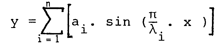
- (a:
- Amplitude der Wellenlänge
- i:
- Index der Wellenlänge im Wellenlenlängenspektrogramm
- λ:
- Wellenlänge
- x:
- Position in Garnlängsrichtung)
- (a:
- Wavelength amplitude
- i:
- Index of the wavelength in the wavelength spectrogram
- λ:
- wavelength
- x:
- Position in yarn length direction)
In der Praxis gilt für die Berechnung von I vorzugsweise:
- (y₁:
- Abweichung vom Minimalwert; dabei ist y so verschoben, dass y₁ immer positiv ist)
- (k, K:
- konstanter Multiplikator)
- (y₁:
- Deviation from minimum value; y is shifted so that y₁ is always positive)
- (k, K:
- constant multiplier)
Die Frage, ob man für die nicht-seltenen Fehler vom Diagramm ausgehen und auf dem Bildschirn das reale Garn abbilden, oder ob man vom Spektrogramm ausgehen und ein aus statistischen Werten rekonstruiertes, simuliertes Garn abbilden soll, wird heute zugunsten des Spektrogramms beantwortet werden. Denn im Spektrogramm werden in der Regel wesentlich kleinere Wellenlängen registriert als im Diagramm, da ein Diagramm hoher Auflösung eine sehr grosse Datenmenge ergeben würde. Somit steht oft kein Diagramm mit der zur Darstellung des Schaubildes erforderlichen Auflösung zur Verfügung.The question of whether one should start from the diagram for the not uncommon errors and depict the real yarn on the screen, or whether one should start from the spectrogram and depict a simulated yarn reconstructed from statistical values will be answered today in favor of the spectrogram. This is because the spectrogram generally records much smaller wavelengths than in the diagram, since a high-resolution diagram would result in a very large amount of data. As a result, there is often no diagram available with the resolution required to display the diagram.
Ausserdem ist fraglich, ob beispielsweise Nissen in diesem Abbild des realen Garns erkannt würden. Entnimmt man hingegen die Nissen dem Nissenkanal und streut sie mit entsprechender Dichte und unter geeigneter Kontrastverstärkung, wie zum Beispiel Einfärbung, in das Bild, dann werden sie mit Sicherheit auch auf dem Bildschirm erkannt. Hingegen verlangt die fortlaufende Rekonstruktion des Diagramms aus dem Spektrogramm einen wesentlich höheren Rechenaufwand als die direkte Umsetzung des Diagramms in Helligkeits- oder Farbwerte.It is also questionable whether, for example, nits would be recognized in this image of the real yarn. If, on the other hand, you take the nits out of the nits channel and sprinkle them with the appropriate density and with suitable contrast enhancement, such as coloring, for example, then they will certainly be recognized on the screen. On the other hand, the continuous reconstruction of the diagram from the spectrogram requires a considerably higher computing effort than the direct conversion of the diagram into brightness or color values.
Die Fig. 4a und 4b zeigen je eine aus den Spektrogrammen von Fig. 3 berechnete Schautafel-Simulation für die beiden Proben 1 beziehungsweise 2. Diese Simulationen ergeben das für den Fachmann erwartete Ergebnis mit Querstreifen für Probe 1 und einem Moiré-Muster für Probe 2, welche durch die durch die schraffierten Kamine in den beiden Spektrogrammen gekennzeichneten periodischen Fehler bedingt sind. Dieses Ergebnis be weist die Praxistauglichkeit des beschriebenen Verfahrens.4a and 4b each show a chart simulation for the two
Claims (14)

Applications Claiming Priority (3)
| Application Number | Priority Date | Filing Date | Title |
|---|---|---|---|
| CH192692 | 1992-06-18 | ||
| CH1926/92 | 1992-06-18 | ||
| CH192692A CH684129A5 (en) | 1992-06-18 | 1992-06-18 | Method and device for assessing the effect of yarn defects on woven or knitted fabric. |
Publications (3)
| Publication Number | Publication Date |
|---|---|
| EP0578975A1 true EP0578975A1 (en) | 1994-01-19 |
| EP0578975B1 EP0578975B1 (en) | 1999-04-21 |
| EP0578975B2 EP0578975B2 (en) | 2005-01-12 |
Family
ID=4221829
Family Applications (1)
| Application Number | Title | Priority Date | Filing Date |
|---|---|---|---|
| EP19930109438 Expired - Lifetime EP0578975B2 (en) | 1992-06-18 | 1993-06-14 | Method and apparatus for predicting the effect of yarn defects on the appearance of textiles or fabrics |
Country Status (5)
| Country | Link |
|---|---|
| EP (1) | EP0578975B2 (en) |
| JP (1) | JP2747451B2 (en) |
| CN (1) | CN1043910C (en) |
| CH (1) | CH684129A5 (en) |
| DE (1) | DE59309522D1 (en) |
Cited By (19)
| Publication number | Priority date | Publication date | Assignee | Title |
|---|---|---|---|---|
| US5654554A (en) * | 1994-11-29 | 1997-08-05 | Zellweger Luwa Ag | Method and apparatus for the recording of properties on elongate bodies |
| WO1997047959A1 (en) * | 1996-06-12 | 1997-12-18 | Zellweger Luwa Ag | Method of evaluating the effects of yarn defects on textile surface configuration |
| EP0875611A1 (en) * | 1997-05-02 | 1998-11-04 | Ingenieurbüro Dieter Zweigle | Apparatus for optimizing fabrics based on yarn data and optimizing process |
| EP0880028A1 (en) * | 1997-05-20 | 1998-11-25 | Zellweger Luwa Ag | Testing apparatus for a textile sample that is moved along |
| US5875419A (en) * | 1995-11-13 | 1999-02-23 | Lawson-Hemphill, Inc. | System and method for determining yarn hairiness |
| EP0942282A1 (en) * | 1998-03-13 | 1999-09-15 | Zellweger Luwa Ag | Apparatus for measuring characteristics of a textile product |
| WO1999063139A1 (en) * | 1998-05-29 | 1999-12-09 | Zinser Textilmaschinen Gmbh | Method for producing compacted yarn and device therefor |
| EP0976855A1 (en) * | 1998-07-30 | 2000-02-02 | Fibrevision Limited | Yarn monitoring |
| EP1006225A2 (en) * | 1998-12-02 | 2000-06-07 | W. SCHLAFHORST AG & CO. | Method and device for evaluating the effect of yarn characteristics on the looks of textile surfaces |
| US6130746A (en) * | 1994-03-10 | 2000-10-10 | Lawson-Hemphill, Inc. | System and method for electronically evaluating predicted fabric qualities |
| WO2000073189A1 (en) * | 1999-05-29 | 2000-12-07 | Zellweger Luwa Ag | Method and device for cleaning yarn |
| DE19939711A1 (en) * | 1999-08-21 | 2001-02-22 | Schlafhorst & Co W | Method and device for detecting foreign bodies in a longitudinally moving thread |
| WO2006122722A1 (en) * | 2005-05-14 | 2006-11-23 | Oerlikon Textile Gmbh & Co. Kg | Method and device for simulating a visual pattern of a fiber product and method and device for producing a bcf yarn |
| EP1764429A1 (en) * | 2004-06-07 | 2007-03-21 | Shima Seiki Manufacturing, Ltd. | Yarn image forming apparatus for melange yarn, method of forming yarn image therewith, and program therefor |
| EP1682705B1 (en) * | 2003-10-16 | 2011-05-04 | Oerlikon Textile GmbH & Co. KG | Method for obtaining a visual display if predetermined effects are produced |
| EP2602384A1 (en) | 2011-12-05 | 2013-06-12 | VÚTS, a.s. | Method for detection of appearance characteristics of a yarn in plane and a device to perform the method |
| CN107815762A (en) * | 2017-11-02 | 2018-03-20 | 苏州长风纺织机电科技有限公司 | Multifunctional modular evenness meter |
| CN108733900A (en) * | 2018-04-28 | 2018-11-02 | 江南大学 | A kind of bunchy yarn fabrics appearance model and visual evaluating method |
| CN113281342A (en) * | 2021-05-21 | 2021-08-20 | 绍兴随手智能科技有限公司 | Cloth flaw detection method integrating machine vision and spectrometer |
Families Citing this family (10)
| Publication number | Priority date | Publication date | Assignee | Title |
|---|---|---|---|---|
| EP2278328B1 (en) * | 2005-11-18 | 2013-04-24 | Uster Technologies AG | Method for characterising effect yarn |
| JP5413560B2 (en) * | 2008-09-25 | 2014-02-12 | 村田機械株式会社 | Foreign object detection device, textile machine, and foreign object detection method |
| CN101493449B (en) * | 2008-12-19 | 2012-06-27 | 清华大学深圳研究生院 | Fiber identification method and measurement method for content of fiber constituent in blended fabric |
| CN101831719B (en) * | 2010-05-21 | 2012-05-09 | 江苏神泰科技发展有限公司 | High-performance fiber synchrotron radiation in-situ testing machine |
| CN102980874B (en) * | 2011-09-07 | 2015-01-28 | 沈阳黎明航空发动机(集团)有限责任公司 | Method for making map for detecting microporosity |
| CN108026677B (en) * | 2015-09-10 | 2021-03-23 | 乌斯特技术股份公司 | Method for predicting the appearance of a fabric surface, readable medium, image database and method for producing said image database |
| CN105734740B (en) * | 2016-04-29 | 2017-12-26 | 江苏理工学院 | A kind of spinning frame yarn multiple target device for dynamically detecting and its detection method |
| US11524136B2 (en) * | 2018-12-24 | 2022-12-13 | Biosense Webster (Israel) Ltd. | Non-invasive measurement of the pitch of a braid |
| CN110108709B (en) * | 2019-06-12 | 2023-12-22 | 辽东学院 | Method for measuring warp-wise and weft-wise density of fabric |
| CN117449000B (en) * | 2023-12-25 | 2024-03-15 | 福建旭源纺织有限公司 | Yarn quality detection device and system of spinning frame |
Citations (3)
| Publication number | Priority date | Publication date | Assignee | Title |
|---|---|---|---|---|
| EP0199552A2 (en) * | 1985-04-18 | 1986-10-29 | E.I. Du Pont De Nemours And Company | Method of simulating by computer the appearance properties of a warp knit fabric |
| EP0249741A2 (en) * | 1986-05-21 | 1987-12-23 | Zellweger Luwa Ag | Display process for measurements in graphical form in testing appliances for textile test goods, and device for the performance of the process |
| EP0439659A1 (en) * | 1990-02-01 | 1991-08-07 | Iam - Institut Für Angewandte Mikroelektronik Gmbh | Method and device for producing textile patterns using fancy yarns on a monitor |
-
1992
- 1992-06-18 CH CH192692A patent/CH684129A5/en not_active IP Right Cessation
- 1992-09-30 JP JP4300251A patent/JP2747451B2/en not_active Expired - Lifetime
-
1993
- 1993-06-14 DE DE59309522T patent/DE59309522D1/en not_active Expired - Lifetime
- 1993-06-14 EP EP19930109438 patent/EP0578975B2/en not_active Expired - Lifetime
- 1993-06-18 CN CN93107346A patent/CN1043910C/en not_active Expired - Lifetime
Patent Citations (3)
| Publication number | Priority date | Publication date | Assignee | Title |
|---|---|---|---|---|
| EP0199552A2 (en) * | 1985-04-18 | 1986-10-29 | E.I. Du Pont De Nemours And Company | Method of simulating by computer the appearance properties of a warp knit fabric |
| EP0249741A2 (en) * | 1986-05-21 | 1987-12-23 | Zellweger Luwa Ag | Display process for measurements in graphical form in testing appliances for textile test goods, and device for the performance of the process |
| EP0439659A1 (en) * | 1990-02-01 | 1991-08-07 | Iam - Institut Für Angewandte Mikroelektronik Gmbh | Method and device for producing textile patterns using fancy yarns on a monitor |
Cited By (30)
| Publication number | Priority date | Publication date | Assignee | Title |
|---|---|---|---|---|
| US6130746A (en) * | 1994-03-10 | 2000-10-10 | Lawson-Hemphill, Inc. | System and method for electronically evaluating predicted fabric qualities |
| US5654554A (en) * | 1994-11-29 | 1997-08-05 | Zellweger Luwa Ag | Method and apparatus for the recording of properties on elongate bodies |
| US5875419A (en) * | 1995-11-13 | 1999-02-23 | Lawson-Hemphill, Inc. | System and method for determining yarn hairiness |
| WO1997047959A1 (en) * | 1996-06-12 | 1997-12-18 | Zellweger Luwa Ag | Method of evaluating the effects of yarn defects on textile surface configuration |
| EP0875611A1 (en) * | 1997-05-02 | 1998-11-04 | Ingenieurbüro Dieter Zweigle | Apparatus for optimizing fabrics based on yarn data and optimizing process |
| WO1998050613A1 (en) * | 1997-05-02 | 1998-11-12 | Ingenieurbüro Dieter Zweigle | Device for optimizing fabrics based on measured thread data and optimization method |
| EP0880028A1 (en) * | 1997-05-20 | 1998-11-25 | Zellweger Luwa Ag | Testing apparatus for a textile sample that is moved along |
| EP0942282A1 (en) * | 1998-03-13 | 1999-09-15 | Zellweger Luwa Ag | Apparatus for measuring characteristics of a textile product |
| US6412342B1 (en) | 1998-03-13 | 2002-07-02 | Zellweger Luwa Ag | Device for measuring properties of a textile product |
| WO1999063139A1 (en) * | 1998-05-29 | 1999-12-09 | Zinser Textilmaschinen Gmbh | Method for producing compacted yarn and device therefor |
| EP0976855A1 (en) * | 1998-07-30 | 2000-02-02 | Fibrevision Limited | Yarn monitoring |
| US6449008B1 (en) | 1998-07-30 | 2002-09-10 | The Merlin Partnership | Yarn monitoring |
| DE19855588A1 (en) * | 1998-12-02 | 2000-06-08 | Schlafhorst & Co W | Method and device for evaluating the effect of yarn properties on the appearance of textile fabrics |
| EP1006225A3 (en) * | 1998-12-02 | 2000-10-18 | W. SCHLAFHORST AG & CO. | Method and device for evaluating the effect of yarn characteristics on the looks of textile surfaces |
| EP1006225A2 (en) * | 1998-12-02 | 2000-06-07 | W. SCHLAFHORST AG & CO. | Method and device for evaluating the effect of yarn characteristics on the looks of textile surfaces |
| WO2000073189A1 (en) * | 1999-05-29 | 2000-12-07 | Zellweger Luwa Ag | Method and device for cleaning yarn |
| US6922604B2 (en) | 1999-05-29 | 2005-07-26 | Uster Technologies Ag | Process and device for adjusting clearing limits |
| DE19939711A1 (en) * | 1999-08-21 | 2001-02-22 | Schlafhorst & Co W | Method and device for detecting foreign bodies in a longitudinally moving thread |
| US6380548B1 (en) | 1999-08-21 | 2002-04-30 | W. Schlafhorst Ag & Co. | Method and device for detecting foreign matter in longitudinally traveling yarn |
| DE19939711B4 (en) * | 1999-08-21 | 2015-03-12 | Saurer Germany Gmbh & Co. Kg | Method and device for detecting foreign bodies in a longitudinally moved thread |
| EP1682705B1 (en) * | 2003-10-16 | 2011-05-04 | Oerlikon Textile GmbH & Co. KG | Method for obtaining a visual display if predetermined effects are produced |
| EP1764429A1 (en) * | 2004-06-07 | 2007-03-21 | Shima Seiki Manufacturing, Ltd. | Yarn image forming apparatus for melange yarn, method of forming yarn image therewith, and program therefor |
| EP1764429A4 (en) * | 2004-06-07 | 2009-09-09 | Shima Seiki Mfg | Yarn image forming apparatus for melange yarn, method of forming yarn image therewith, and program therefor |
| WO2006122722A1 (en) * | 2005-05-14 | 2006-11-23 | Oerlikon Textile Gmbh & Co. Kg | Method and device for simulating a visual pattern of a fiber product and method and device for producing a bcf yarn |
| EP2602384A1 (en) | 2011-12-05 | 2013-06-12 | VÚTS, a.s. | Method for detection of appearance characteristics of a yarn in plane and a device to perform the method |
| CN107815762A (en) * | 2017-11-02 | 2018-03-20 | 苏州长风纺织机电科技有限公司 | Multifunctional modular evenness meter |
| CN108733900A (en) * | 2018-04-28 | 2018-11-02 | 江南大学 | A kind of bunchy yarn fabrics appearance model and visual evaluating method |
| CN108733900B (en) * | 2018-04-28 | 2022-08-12 | 江南大学 | Method for appearance simulation and visual evaluation of bunchy yarn fabric |
| CN113281342A (en) * | 2021-05-21 | 2021-08-20 | 绍兴随手智能科技有限公司 | Cloth flaw detection method integrating machine vision and spectrometer |
| CN113281342B (en) * | 2021-05-21 | 2024-04-26 | 绍兴随手智能科技有限公司 | Cloth flaw detection method integrating machine vision and spectrometer |
Also Published As
| Publication number | Publication date |
|---|---|
| DE59309522D1 (en) | 1999-05-27 |
| CN1080001A (en) | 1993-12-29 |
| JPH063287A (en) | 1994-01-11 |
| EP0578975B2 (en) | 2005-01-12 |
| EP0578975B1 (en) | 1999-04-21 |
| CH684129A5 (en) | 1994-07-15 |
| CN1043910C (en) | 1999-06-30 |
| JP2747451B2 (en) | 1998-05-06 |
Similar Documents
| Publication | Publication Date | Title |
|---|---|---|
| EP0578975B1 (en) | Method and apparatus for predicting the effect of yarn defects on the appearance of textiles or fabrics | |
| EP0893520B1 (en) | Method for displaying the properties of elongated textile sample bodies | |
| EP2270494B1 (en) | Method for characterising effect yarn | |
| DE69420972T2 (en) | SYSTEM FOR ELECTRICALLY DISPLAYING YARN QUALITY | |
| US5671061A (en) | Method and apparatus for assessing the effect of yarn faults on woven or knitted fabrics | |
| EP1100989B1 (en) | Method and device for evaluating defects in flat textile structures | |
| EP0904532B1 (en) | Method of evaluating the effects of yarn defects on textile surface configuration | |
| DE69031559T2 (en) | FIBER TEST PROCEDURE | |
| EP0249741B1 (en) | Display process for measurements in graphical form in testing appliances for textile test goods, and device for the performance of the process | |
| DE19818069A1 (en) | System to register optical characteristics of yarn | |
| EP3320134B1 (en) | Forecasting the appearance of a textile surface | |
| US6683687B1 (en) | Method and apparatus for assessing the effect of yarn faults on woven or knitted fabrics | |
| DE2116782B2 (en) | Method and device for determining the volume per unit length of thread-like products in the textile industry | |
| DE3628654A1 (en) | Method for determining the twist of a twine | |
| EP0125556B1 (en) | Process and device for controlling the dye receptivity of textiles | |
| WO1999054532A1 (en) | Method and device for determining the optical features of threads | |
| WO2013185248A1 (en) | Comparing the quality of elongate textile samples | |
| DE69011665T2 (en) | Method and device for the objective evaluation of the crushing of plush fabrics, in particular velor, for covering automobile seats. | |
| DE69408367T2 (en) | Method and device for mechanical testing of optical fibers | |
| DE102007028651A1 (en) | Method for visualization of frequency distribution of errors in longitudinally moving yarn, involves manufacturing of yarn in cross-wound bobbin and representing detected error frequency as color point | |
| EP1678370A1 (en) | Method for processing signals obtained by scanning planar textile structures | |
| DE102007043353A1 (en) | Method and device for detecting contaminants in longitudinally moved yarn | |
| CH698764A2 (en) | Method and device for optical detection of foreign fibers in a moving fiber strand along. | |
| WO2017041192A1 (en) | Prediction of the appearance of a textile sheet | |
| DE29724825U1 (en) | System to visually display a simulation of an actual made up fabric - by simulating a yarn from parameters determined directly from a actual yarn and user defined fabric parameters,the actual yarn modelled by using position and orientation vectors which are used to model the actual fabric |
Legal Events
| Date | Code | Title | Description |
|---|---|---|---|
| PUAI | Public reference made under article 153(3) epc to a published international application that has entered the european phase |
Free format text: ORIGINAL CODE: 0009012 |
|
| AK | Designated contracting states |
Kind code of ref document: A1 Designated state(s): BE DE ES FR GB IT |
|
| 17P | Request for examination filed |
Effective date: 19940712 |
|
| RAP1 | Party data changed (applicant data changed or rights of an application transferred) |
Owner name: ZELLWEGER LUWA AG |
|
| 17Q | First examination report despatched |
Effective date: 19971128 |
|
| GRAG | Despatch of communication of intention to grant |
Free format text: ORIGINAL CODE: EPIDOS AGRA |
|
| GRAG | Despatch of communication of intention to grant |
Free format text: ORIGINAL CODE: EPIDOS AGRA |
|
| GRAH | Despatch of communication of intention to grant a patent |
Free format text: ORIGINAL CODE: EPIDOS IGRA |
|
| GRAH | Despatch of communication of intention to grant a patent |
Free format text: ORIGINAL CODE: EPIDOS IGRA |
|
| GRAA | (expected) grant |
Free format text: ORIGINAL CODE: 0009210 |
|
| AK | Designated contracting states |
Kind code of ref document: B1 Designated state(s): BE DE ES FR GB IT |
|
| ITF | It: translation for a ep patent filed | ||
| GBT | Gb: translation of ep patent filed (gb section 77(6)(a)/1977) |
Effective date: 19990427 |
|
| REF | Corresponds to: |
Ref document number: 59309522 Country of ref document: DE Date of ref document: 19990527 |
|
| PGFP | Annual fee paid to national office [announced via postgrant information from national office to epo] |
Ref country code: ES Payment date: 19990621 Year of fee payment: 7 |
|
| ET | Fr: translation filed | ||
| PG25 | Lapsed in a contracting state [announced via postgrant information from national office to epo] |
Ref country code: ES Free format text: LAPSE BECAUSE OF FAILURE TO SUBMIT A TRANSLATION OF THE DESCRIPTION OR TO PAY THE FEE WITHIN THE PRESCRIBED TIME-LIMIT Effective date: 19991019 |
|
| PLBQ | Unpublished change to opponent data |
Free format text: ORIGINAL CODE: EPIDOS OPPO |
|
| PLBI | Opposition filed |
Free format text: ORIGINAL CODE: 0009260 |
|
| 26 | Opposition filed |
Opponent name: ZWEIGLE TEXTILPRUEFMASCHINE GMBH & CO.KG Effective date: 20000120 Opponent name: LAWSON-HEMPHILL INC. Effective date: 20000118 |
|
| PLBF | Reply of patent proprietor to notice(s) of opposition |
Free format text: ORIGINAL CODE: EPIDOS OBSO |
|
| PLBF | Reply of patent proprietor to notice(s) of opposition |
Free format text: ORIGINAL CODE: EPIDOS OBSO |
|
| RTI2 | Title (correction) |
Free format text: METHOD AND APPARATUS FOR PREDICTING THE EFFECT OF YARN DEFECTS ON THE APPEARANCE OF TEXTILES OR FABRICS |
|
| RTI2 | Title (correction) |
Free format text: METHOD AND APPARATUS FOR PREDICTING THE EFFECT OF YARN DEFECTS ON THE APPEARANCE OF TEXTILES OR FABRICS |
|
| PLBO | Opposition rejected |
Free format text: ORIGINAL CODE: EPIDOS REJO |
|
| RTI2 | Title (correction) |
Free format text: METHOD AND APPARATUS FOR PREDICTING THE EFFECT OF YARN DEFECTS ON THE APPEARANCE OF TEXTILES OR FABRICS |
|
| RTI2 | Title (correction) |
Free format text: METHOD AND APPARATUS FOR PREDICTING THE EFFECT OF YARN DEFECTS ON THE APPEARANCE OF TEXTILES OR FABRICS |
|
| APAC | Appeal dossier modified |
Free format text: ORIGINAL CODE: EPIDOS NOAPO |
|
| APAE | Appeal reference modified |
Free format text: ORIGINAL CODE: EPIDOS REFNO |
|
| REG | Reference to a national code |
Ref country code: GB Ref legal event code: IF02 |
|
| APAC | Appeal dossier modified |
Free format text: ORIGINAL CODE: EPIDOS NOAPO |
|
| APAE | Appeal reference modified |
Free format text: ORIGINAL CODE: EPIDOS REFNO |
|
| REG | Reference to a national code |
Ref country code: FR Ref legal event code: TP |
|
| REG | Reference to a national code |
Ref country code: FR Ref legal event code: GC |
|
| REG | Reference to a national code |
Ref country code: GB Ref legal event code: 732E |
|
| REG | Reference to a national code |
Ref country code: GB Ref legal event code: 732E |
|
| APBU | Appeal procedure closed |
Free format text: ORIGINAL CODE: EPIDOSNNOA9O |
|
| PUAH | Patent maintained in amended form |
Free format text: ORIGINAL CODE: 0009272 |
|
| STAA | Information on the status of an ep patent application or granted ep patent |
Free format text: STATUS: PATENT MAINTAINED AS AMENDED |
|
| 27A | Patent maintained in amended form |
Effective date: 20050112 |
|
| AK | Designated contracting states |
Kind code of ref document: B2 Designated state(s): BE DE ES FR GB IT |
|
| REG | Reference to a national code |
Ref country code: ES Ref legal event code: FD2A Effective date: 20000615 |
|
| GBTA | Gb: translation of amended ep patent filed (gb section 77(6)(b)/1977) | ||
| APAH | Appeal reference modified |
Free format text: ORIGINAL CODE: EPIDOSCREFNO |
|
| ET3 | Fr: translation filed ** decision concerning opposition | ||
| PGFP | Annual fee paid to national office [announced via postgrant information from national office to epo] |
Ref country code: FR Payment date: 20060608 Year of fee payment: 14 |
|
| PGFP | Annual fee paid to national office [announced via postgrant information from national office to epo] |
Ref country code: GB Payment date: 20060614 Year of fee payment: 14 |
|
| REG | Reference to a national code |
Ref country code: GB Ref legal event code: 732E |
|
| REG | Reference to a national code |
Ref country code: FR Ref legal event code: RG |
|
| PGFP | Annual fee paid to national office [announced via postgrant information from national office to epo] |
Ref country code: BE Payment date: 20070817 Year of fee payment: 15 |
|
| GBPC | Gb: european patent ceased through non-payment of renewal fee |
Effective date: 20070614 |
|
| REG | Reference to a national code |
Ref country code: FR Ref legal event code: ST Effective date: 20080229 |
|
| PG25 | Lapsed in a contracting state [announced via postgrant information from national office to epo] |
Ref country code: GB Free format text: LAPSE BECAUSE OF NON-PAYMENT OF DUE FEES Effective date: 20070614 |
|
| PG25 | Lapsed in a contracting state [announced via postgrant information from national office to epo] |
Ref country code: FR Free format text: LAPSE BECAUSE OF NON-PAYMENT OF DUE FEES Effective date: 20070702 |
|
| BERE | Be: lapsed |
Owner name: *USTER TECHNOLOGIES A.G. Effective date: 20080630 |
|
| PG25 | Lapsed in a contracting state [announced via postgrant information from national office to epo] |
Ref country code: BE Free format text: LAPSE BECAUSE OF NON-PAYMENT OF DUE FEES Effective date: 20080630 |
|
| PGFP | Annual fee paid to national office [announced via postgrant information from national office to epo] |
Ref country code: IT Payment date: 20110620 Year of fee payment: 19 Ref country code: DE Payment date: 20110608 Year of fee payment: 19 |
|
| PG25 | Lapsed in a contracting state [announced via postgrant information from national office to epo] |
Ref country code: IT Free format text: LAPSE BECAUSE OF NON-PAYMENT OF DUE FEES Effective date: 20120614 |
|
| REG | Reference to a national code |
Ref country code: DE Ref legal event code: R119 Ref document number: 59309522 Country of ref document: DE Effective date: 20130101 |
|
| PG25 | Lapsed in a contracting state [announced via postgrant information from national office to epo] |
Ref country code: DE Free format text: LAPSE BECAUSE OF NON-PAYMENT OF DUE FEES Effective date: 20130101 |