EP0578433A2 - Error and loss correction in a data base stored on a two dimensional medium and method - Google Patents
Error and loss correction in a data base stored on a two dimensional medium and method Download PDFInfo
- Publication number
- EP0578433A2 EP0578433A2 EP93305120A EP93305120A EP0578433A2 EP 0578433 A2 EP0578433 A2 EP 0578433A2 EP 93305120 A EP93305120 A EP 93305120A EP 93305120 A EP93305120 A EP 93305120A EP 0578433 A2 EP0578433 A2 EP 0578433A2
- Authority
- EP
- European Patent Office
- Prior art keywords
- check
- code
- codes
- checking
- error
- Prior art date
- Legal status (The legal status is an assumption and is not a legal conclusion. Google has not performed a legal analysis and makes no representation as to the accuracy of the status listed.)
- Granted
Links
- 238000000034 method Methods 0.000 title claims description 34
- 239000000463 material Substances 0.000 claims description 16
- 230000006735 deficit Effects 0.000 claims description 13
- 239000011159 matrix material Substances 0.000 claims description 5
- 239000003086 colorant Substances 0.000 claims description 3
- 230000008021 deposition Effects 0.000 claims 1
- 238000010586 diagram Methods 0.000 description 5
- 241001124553 Lepismatidae Species 0.000 description 2
- 238000001514 detection method Methods 0.000 description 2
- 230000001771 impaired effect Effects 0.000 description 2
- 230000007774 longterm Effects 0.000 description 2
- 241000607479 Yersinia pestis Species 0.000 description 1
- 230000032683 aging Effects 0.000 description 1
- 230000004075 alteration Effects 0.000 description 1
- 230000001419 dependent effect Effects 0.000 description 1
- 230000000694 effects Effects 0.000 description 1
- 230000008030 elimination Effects 0.000 description 1
- 238000003379 elimination reaction Methods 0.000 description 1
- 239000007788 liquid Substances 0.000 description 1
- 230000005055 memory storage Effects 0.000 description 1
- 239000000049 pigment Substances 0.000 description 1
- 239000000843 powder Substances 0.000 description 1
- 239000007787 solid Substances 0.000 description 1
- 239000000126 substance Substances 0.000 description 1
- 230000009897 systematic effect Effects 0.000 description 1
- 239000002023 wood Substances 0.000 description 1
Images


Classifications
-
- G—PHYSICS
- G06—COMPUTING; CALCULATING OR COUNTING
- G06K—GRAPHICAL DATA READING; PRESENTATION OF DATA; RECORD CARRIERS; HANDLING RECORD CARRIERS
- G06K19/00—Record carriers for use with machines and with at least a part designed to carry digital markings
- G06K19/06—Record carriers for use with machines and with at least a part designed to carry digital markings characterised by the kind of the digital marking, e.g. shape, nature, code
- G06K19/06009—Record carriers for use with machines and with at least a part designed to carry digital markings characterised by the kind of the digital marking, e.g. shape, nature, code with optically detectable marking
- G06K19/06046—Constructional details
- G06K19/06075—Constructional details the marking containing means for error correction
-
- G—PHYSICS
- G06—COMPUTING; CALCULATING OR COUNTING
- G06K—GRAPHICAL DATA READING; PRESENTATION OF DATA; RECORD CARRIERS; HANDLING RECORD CARRIERS
- G06K19/00—Record carriers for use with machines and with at least a part designed to carry digital markings
- G06K19/06—Record carriers for use with machines and with at least a part designed to carry digital markings characterised by the kind of the digital marking, e.g. shape, nature, code
- G06K19/06009—Record carriers for use with machines and with at least a part designed to carry digital markings characterised by the kind of the digital marking, e.g. shape, nature, code with optically detectable marking
- G06K19/06037—Record carriers for use with machines and with at least a part designed to carry digital markings characterised by the kind of the digital marking, e.g. shape, nature, code with optically detectable marking multi-dimensional coding
Definitions
- This invention relates to a data base correctable against error and loss and method of correction; and more particularly to such a data base stored on the surface of a two dimensional base medium.
- this invention may provide such a data base and method which can correct "blot" errors caused by impairments in the base medium.
- this invention may provide such a data base and method which can correct blot errors introduced by long term storage.
- this invention may provide such a data base and method in which the data base is permutated and inverse permutated to reduce the effect of blot errors.
- this invention may provide such a data base and method in which the data base may be corrected and refreshed.
- the invention provides a digital data base having record data codes representing an initial digital record, and having redundant check codes and one or more redundant check-check codes.
- the codes are stored in a two dimensional code storage area on the surface of the base medium at defined positions therein.
- the codes have code bit states defined for example by the presence or absence of toner material deposited on the base medium.
- a plurality of error checking sets may be formed by the code sites, each containing one or more data codes and one or more check codes.
- Each data code site and each check code site may be included in "L" error checking sets to provide "L" levels of inter-locking error checking.
- a plurality of error checking-checking sets may be formed by the code sites, each containing one or more check codes and one or more check-check codes. Each check code site and each check-check code site may also be included in "L" error checking-checking sets.
- the invention further provides a method of storing and retrieving and correcting the digital data base.
- a base medium is provided for carrying the codes of the digital data base. The codes are retrieved from the base medium into an retrieval memory, and examined to locate errors revealed for example by inconsistencies in the error correcting relationship between the "L" inter-locked error checking sets. The errors in the codes of the error checking sets are corrected if any errors exist. The examination and correction steps are iterated until a predetermined error condition has been established.
- each reference numeral in the above Figures indicates the Figure in which that element is shown.
- the second digit indicates related structural elements, and the final letter indicates a sub-portion of an element.
- a digital data base 10 having record data codes representing an initial digital record is printed at predetermined code sites 12 within two dimensional code storage area 14 on the surface of on base medium 10B.
- the digital data base includes redundant check codes and one or more redundant check-check codes for permitting data error and data loss correction.
- the two dimensional code storage area has a coordinate system for defining code positions therein.
- the code sites are physically positioned within the code storage area at predetermined coordinates.
- the bit states of the codes are defined by the presence or absence of toner material deposited on the base medium.
- a plurality of error checking sets are formed by the code sites, each containing one or more data codes and one or more check codes.
- the bits in the check codes in each error checking set are determined by the bits in the data codes of the same error checking set, and are in error correcting relationship therewith.
- Each data code and each check code are included in "L" error checking sets to provide “L” levels of inter-locking error checking and correcting.
- Each error checking-checking set contains one or more check codes and one or more check-check codes.
- the bits in the check-check codes in each error checking-checking set are determined by the bits in the check codes thereof, and are in error correcting relationship therewith.
- Each check code and each check-check code are also included in "L" error checking-checking sets to provide "L" Levels of interlocking error checking-checking.
- each code site 22 within the code storage area 24 is positioned along a row axis and also along a column axis forming a pattern of intersecting rows and columns having "R" rows and "C” columns.
- the coordinate system for defining the position of each code site is a row and column coordinate system.
- the number or rows "R” is equal to the number of columns "C”.
- code sites 32 are arranged in storage area 34 with "R” and "C" selected so as not to have a common divider so as to avoid error correction looping.
- Each error checking set may be contained along a row or column forming (R-1) row error checking sets and (C-1) column error checking sites as shown in Figure 2.
- Each of the R-1 row error checking sets has C code sites containing C-1 data codes (Dt) and one check code (Ck); and each of the C-1 column error checking sets has R code sites containing R-1 data codes (Dt) and one check code (Ck).
- the error checking-checking sets may also be contained along a row or column forming one row error checking-checking set and one column error checking-checking set.
- the one row error checking-checking set has C sites containing (C-1) check codes (Ck) plus one checking-checking code (CC), and the one column error checking-checking set has R sites containing (R-1) check codes (Ck) plus the one checking-checking code (CC).
- each data code site (Dt) and each check code site (Ck) are included in two checking sets, a row checking set and an intersecting column checking set.
- Each check code site (Ck) and each check-check code site (CC) are also included in two checking sets, a row checking-checking set and an intersecting column checking-checking set.
- each of the data codes occupies a code site at the intersection of a row and column.
- Each data code is in error correcting relationship with the C-2 other data codes plus the one check code along that row, and is also in error correcting relationship with the R-2 other data codes plus the one check code along that column.
- the check codes also occupy a code site at the intersection of a rowand column, and are in error correcting relationship with the C-2 other check codes plus one check-check code along that row, and in error correcting relationship with the R-2 other check codes plus one check-check code along that column.
- the number of levels "L" may be greater than 2 even though the data base has only two physical dimensions (one row dimension and one column dimension).
- Mathematical dimensions may be employed which to not correlate with the row and column dimensions. Mathematical dimensions are manifested by lists of addresses in the data base memory.
- the (C-1) row data check sites (Ck) plus the one check-check code site (CC) forming the row checking-checking set are positioned along an exterior row near the bottom edge of code storage area 24.
- the (R-1) column check code sites (Ck) plus the one check-check code site (CC) forming the column checking-checking set are positioned along the right hand exterior column.
- the one code checking-checking site (CC) is positioned at the intersection site between the exterior row and the exterior column at a corner of code storage area 24. The exterior position of the checking-checking sets to permit fast reading of the interior record data codes by ignoring the exterior row and column.
- the row checking set is positioned along an interior row within code storage area 34, and the column checking set is also positioned along an interior column.
- the one code checking-checking site (CC) is positioned at the intersection site between the interior row and the interior column within code storage area 34.
- each code site contains a single data unit such as one symbol or character.
- Figure 4A shows a conventional code format having "N" (eight) serial bits forming a single byte, which yields 2-to-the-Nth (or 256) possible codes per byte.
- Figure 4B shows an "E entries out of L locations" type code format described in US Patent Application SN 07/807,227 entitled “DATA FORMAT FOR RECORDING DIGITAL DATA AND METHOD” filed on December 16, 1991 by the present inventor. Toner is deposited in any four of eight locations within the code site. The remaining four locations remain untoned (empty).
- the digital format may be binary based, having two code states per bit as shown in Figure 4A employing a single color recording material such as dark toner against a light base medium.
- One state is represented by the presence of toner material (solid black dot) and the other state is represented by the absence of toner material (clear dot).
- the base medium may be any suitable two dimensional sheet like structure such as paper with sufficient body to retain the toner recording material in position within the code site. Paper remains two dimensional in the sense of this invention even though the sheets may curl or become folded into the third dimension.
- the recording material may be any suitable powder or liquid deposited on the base medium.
- the digital format of the codes may be multinary based, having M code states per bit by employing greyscale or colored ink.
- the greyscale format employs toner material of a single color.
- the M code states per bit are determined by M greyscale levels. That is, by the intensity of the deposited toner material.
- the color format (shown in Figure 4B) is a color based multinary code having employing M colors of toner which provide M code states per bit, yielding M-to-the-Nth possible codes.
- the embodiment of Figure 4B employs four entries in eight locations with four colors yielding 256 possible codes. Red color toner is indicated by the dot containing the letter "R”. Green toner is indicated by the letter "G”. Blue is indicated by the letter "B", and yellow by the letter "y”.
- the method of storing and retrieving and correcting a digital data base having record data codes representing an initial digital record is shown in Figure 5.
- the stages of the data base are illustrated in Figure 6A-F.
- the data base includes redundant check codes and one or more redundant check-check codes which are dependent on the record data codes.
- the codes are arranged in error checking sets of codes in error correcting relationship. Each code is included in "L" error checking sets to provide "L" levels of inter-lok- ked error checking.
- the initial memory is the input mechanism for entering data to be examined and corrected into the system.
- the initial memory may be any suitable memory device such as a electronic memory or a magnetic memory such as tapes, hard disks or floppy disks.
- the base medium carrying the codes of the data base ( Figure 6C).
- the base medium is stored under conditions suitable for years of storage, perhaps as long as ten or twenty years. Such long term storage is common for data which is very bulky or seldom (if ever) accessed.
- the data may be "off loaded” from crowded magnetic memory storage, and stored on paper in a cool, dry environment free from silverfish and other life forms.
- a scanning device of appropriate resolution is a suitable device for retrieving the dots of toner and (absence of toner) into binary "1"s and "0"s.
- the iteration cycles of the examination and correction steps are continued until a desireable predetermined condition is attained.
- the nature of the predetermined condition depends on the error limitations of the data processing application. The following are some of the predetermined conditions which may stop the iteration cycles and terminate the method.
- This preferred predetermined condition is attained when all of the errors have been corrected.
- the corrected condition is manifested by the elimination of inconsistencies in the checking sets and checking-checking sets.
- the corrected condition may be attained after a single iteration or several iteration cycles.
- the initial data base may in fact be error free in which case only one examination is required without correction or iteration.
- the iteration cycles may be terminated when no more changes appear in the iterated codes. That is, the same errors are detected during the examination step of each iteration, but not corrected during the correction step.
- the number Imax is sufficient to eliminate the errors that can be corrected, but small enough to prevent pointless iteration cycles dealing with errors that cannot be corrected. Selection of Imax is a trade-off between speed of operation and degree of correction.
- the record codes may be arranged within the code storage area generally in the same sequence as the codes in the initial record represented by the record data codes. This sequential arrangement provides record continuity between the code storage area and the initial memory. Each code has the same neighbors in both the initial record stored in the initial memory and in the code storage areas printed on the base medium.
- the printed codes may be permuted generally out of the sequence of the initial record in order to reduce the record continuity.
- Each printed code within a permuted data base on the base medium has random neighbors.
- the data base is later inverse permuted in the retrieval memory to restore the record continuity prior to the examination and correction steps.
- the permutation and restoration assists in recovering lost data due to "blot" errors resulting from large impairments in the base medium.
- Figure 6A shows initial record data base 661 in the initial memory, illustrating atypical pair of intersecting code checking sets 67R and 67C of the initial record.
- Row set 67R has eight codes each indicated by an "r”; and column set 67C has six codes each indicated by a "c”.
- the code site at the intersection of row set 67R and column set 67C is indicated by an "i”.
- Figure 6B shows permuted data base 66P printed on a base medium 60P resulting from the permutation of record data base 661 of Figure 6A.
- the permutation has distributed the codes of row set 67R and column set 67C throughout the storage area to reduce the record continuity.
- the distribution may be random but inversable based on random inverse keys with encryption potential.
- the distribution may be systematic and based on a standard permutation key which is included within the initial record as key data.
- the standard permutation minimizes (or at least greatly reduces) the record continuity of permuted data base 66P.
- the subsequent inverse permutation restores the record continuity while producing maximum distribution of the blot impairments.
- the key data defines the permutation of the initial record and the inverse permutation in the retrieval memory.
- the embodiment of Figure 1 shows key data 14K carried on the base medium next to storage areas 14.
- Figure 6C shows blot impaired data base 66B resulting from the extensive use and long storage of printed data base 60P of Figure 6B.
- Data impairments have many forms including data processing errors caused by insufficient electronic signal-to-noise and printing errors caused by toner deposited in the wrong amount or at the wrong place.
- the impairment shown in Figure 6C are blot impairments extending over adjacent rows and adjacent columns. The lost codes within these blot impairments are indicated by an "x" in Figure 6C, and are particularly troublesome because they are clustered together in blots.
- Some blot impairments may result from accidental spills a harmful substances over the base medium which removes or discolors the toner.
- Other blot impairments are caused by loss of contrast due between the dark toner and the light base medium to aging.
- the pigment in the toner may fade and the paper may turn yellow or brown over the years of storage.
- the resulting physical signal-to-noise may be insufficient to maintain error free scanning.
- a major cause of blot impairments is holes in the base medium caused by punch holes 68P, stable rips 68R, torn corners 68T or burrows 68E excavated by silverfish and other pests.
- Figure 6D shows retrieved data base 66R in the retrieval memory resulting by the scanning and inverse permutation of impaired data base 66B of Figure 6C.
- the codes of typical row checking set 67R and typical column checking set 67C have been restored to their original discrete format of an intersecting row and column.
- the restored positions of row set 67R and column set 67C correspond to their initial positions in initial record data base 661.
- the clusters of lost codes (each indicated by an "x") caused by the blot impairments have been distributed throughout the retrieved data base 66R due to the inverse permutation.
- Figure 6E shows corrected data base 66C in the retrieval memory resulting from the examination and correction of the retrieved data base of Figure 6D.
- the lost data has been salvaged by means of the redundant codes and the in error correcting relationship between the code sets.
- Figure 6F shows new data base 60N printed on a new base medium, which provides an error free (or at least error reduced) copy of the data base.
- This "refreshed" data base 60N may be used in a present application or returned to in storage for future use.
- the data density of the data base may by 10,000 codes per square inch (4 entries in 8 locations, see Figure 4B) which can be read by at a scanner resolution of 400 dpi.
- the ratio of record data codes to redundant check codes plus check-check codes may be 4:1. That is, the record data codes may occupy 80% of the toned storage area on the paper, and the error correcting codes (such as Reed-Solomon) may occupy the remaining 20%.
- Suitable techniques such as Berlekamp's iterative algorithm may be employ in the error correction as described in detail in the text "Error Control Coding: Fundamentals and Applications” (pages 170-177) by Shu Lin and Daniel J. Cost- ello, Jr, and published by Prentice-Hall, Inc, Engle- wood Cliffs N.J. (copyright 1983).
- the above specific example is not intended as defining the limitations of the invention. Numerous other applications and configurations are possible.
Landscapes
- Physics & Mathematics (AREA)
- General Physics & Mathematics (AREA)
- Engineering & Computer Science (AREA)
- Theoretical Computer Science (AREA)
- Detection And Correction Of Errors (AREA)
- Techniques For Improving Reliability Of Storages (AREA)
- Accessory Devices And Overall Control Thereof (AREA)
- Information Retrieval, Db Structures And Fs Structures Therefor (AREA)
Abstract
Description
- This invention relates to a data base correctable against error and loss and method of correction; and more particularly to such a data base stored on the surface of a two dimensional base medium.
- Heretofore, digital data has been stored on IBM punch cards as bit punch-outs within a row and column matrix of bit positions across on the card. The data was entered along the rows of the card from left to right starting with the top row. The matrix included a row of redundant parity bits along the bottom row and a column of parity bits along the right hand column, for detecting and correcting small errors. Processing errors introduced by electronic aberrations such as low signal-to-noise caused single bit errors and multiple bit errors ("burst" errors) in the serial data stream. The parity bits permitted the detection and correction of short electronic burst errors which were limited to a single row of punch-outs. However, larger burst errors extending over several rows could not be corrected with these row and column parity bits. In addition, loss of data due to "blot" impairments in the physical structure of the card extending across several adjacent rows and columns could not be corrected with these parity bits.
- Printed bar codes arranged in a row-column matrix have been employed with limited error correction; as disclosed in an article entitled "Information Encoding with Two Dimensional Bar Codes" by Theo Pavli- dis et al, appearing in June 1992 edition of the IEEE at pages 18-28. Figure 9 of this publication shows a row of checksums in code PDF417 format.
- It is therefore an object of this invention to provide a two dimensional data base and method with improved error detection and correction capabilities.
- For example this invention may provide such a data base and method which can correct "blot" errors caused by impairments in the base medium.
- Alternatively this invention may provide such a data base and method which can correct blot errors introduced by long term storage.
- Alternatively this invention may provide such a data base and method in which the data base is permutated and inverse permutated to reduce the effect of blot errors.
- Alternatively this invention may provide such a data base and method in which the data base may be corrected and refreshed.
- The invention provides a digital data base having record data codes representing an initial digital record, and having redundant check codes and one or more redundant check-check codes. The codes are stored in a two dimensional code storage area on the surface of the base medium at defined positions therein. The codes have code bit states defined for example by the presence or absence of toner material deposited on the base medium. A plurality of error checking sets may be formed by the code sites, each containing one or more data codes and one or more check codes. The bits in the check codes-are determined by the bits in the data codes and are in error correcting relationship therewith. Each data code site and each check code site may be included in "L" error checking sets to provide "L" levels of inter-locking error checking. A plurality of error checking-checking sets may be formed by the code sites, each containing one or more check codes and one or more check-check codes. Each check code site and each check-check code site may also be included in "L" error checking-checking sets. The invention further provides a method of storing and retrieving and correcting the digital data base. A base medium is provided for carrying the codes of the digital data base. The codes are retrieved from the base medium into an retrieval memory, and examined to locate errors revealed for example by inconsistencies in the error correcting relationship between the "L" inter-locked error checking sets. The errors in the codes of the error checking sets are corrected if any errors exist. The examination and correction steps are iterated until a predetermined error condition has been established.
- Further objects and advantages of the present data base and the operation of the method will become apparent from the following detailed description and drawing (not drawn to scale) in which:
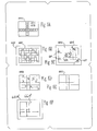
- FIGURE 1 is a diagram of a record data base printed on a paper base medium;
- FIGURE 2 is a diagram of an embodiment of a code storage area for a record data base having record data codes (Dt) and redundant check codes (Ck);
- FIGURE 3 is a diagram of another embodiment of a code storage area;
- FIGURE 4A is a diagram of a single data unit with a serial bit format for storage in a code site;
- FIGURE 4B is a diagram of a single data unit with an E entries out of L locations format;
- FIGURE 5 is a flowchart showing the steps of he method of data correction; and
- FIGURES 6A-F show the stages of the data base during various steps of the method shown in Figure 5.
- The first digit of each reference numeral in the above Figures indicates the Figure in which that element is shown. The second digit indicates related structural elements, and the final letter indicates a sub-portion of an element.
- A
digital data base 10 having record data codes representing an initial digital record is printed at predeterminedcode sites 12 within two dimensionalcode storage area 14 on the surface of on base medium 10B. The digital data base includes redundant check codes and one or more redundant check-check codes for permitting data error and data loss correction. The two dimensional code storage area has a coordinate system for defining code positions therein. The code sites are physically positioned within the code storage area at predetermined coordinates. The bit states of the codes are defined by the presence or absence of toner material deposited on the base medium. - A plurality of error checking sets are formed by the code sites, each containing one or more data codes and one or more check codes. The bits in the check codes in each error checking set are determined by the bits in the data codes of the same error checking set, and are in error correcting relationship therewith. Each data code and each check code are included in "L" error checking sets to provide "L" levels of inter-locking error checking and correcting.
- In addition, a of plurality error checking-checking sets are also formed by the code sites. Each error checking-checking set contains one or more check codes and one or more check-check codes. The bits in the check-check codes in each error checking-checking set are determined by the bits in the check codes thereof, and are in error correcting relationship therewith. Each check code and each check-check code are also included in "L" error checking-checking sets to provide "L" Levels of interlocking error checking-checking.
- In the row-column embodiment shown in Figure 2, each
code site 22 within thecode storage area 24 is positioned along a row axis and also along a column axis forming a pattern of intersecting rows and columns having "R" rows and "C" columns. The coordinate system for defining the position of each code site is a row and column coordinate system. In the embodiment of Figure 2, the number or rows "R" is equal to the number of columns "C". In the embodiment of Figure 3,code sites 32 are arranged in storage area 34 with "R" and "C" selected so as not to have a common divider so as to avoid error correction looping. - Each error checking set may be contained along a row or column forming (R-1) row error checking sets and (C-1) column error checking sites as shown in Figure 2. Each of the R-1 row error checking sets has C code sites containing C-1 data codes (Dt) and one check code (Ck); and each of the C-1 column error checking sets has R code sites containing R-1 data codes (Dt) and one check code (Ck). Further, the error checking-checking sets may also be contained along a row or column forming one row error checking-checking set and one column error checking-checking set. The one row error checking-checking set has C sites containing (C-1) check codes (Ck) plus one checking-checking code (CC), and the one column error checking-checking set has R sites containing (R-1) check codes (Ck) plus the one checking-checking code (CC).
- In the embodiments of Figures 2 and 3, "L" = 2. That is, each data code site (Dt) and each check code site (Ck) are included in two checking sets, a row checking set and an intersecting column checking set. Each check code site (Ck) and each check-check code site (CC) are also included in two checking sets, a row checking-checking set and an intersecting column checking-checking set. As a result of the two level row-column configuration, each of the data codes occupies a code site at the intersection of a row and column. Each data code is in error correcting relationship with the C-2 other data codes plus the one check code along that row, and is also in error correcting relationship with the R-2 other data codes plus the one check code along that column. The check codes also occupy a code site at the intersection of a rowand column, and are in error correcting relationship with the C-2 other check codes plus one check-check code along that row, and in error correcting relationship with the R-2 other check codes plus one check-check code along that column.
- The number of levels "L" may be greater than 2 even though the data base has only two physical dimensions (one row dimension and one column dimension). Mathematical dimensions may be employed which to not correlate with the row and column dimensions. Mathematical dimensions are manifested by lists of addresses in the data base memory.
- In the embodiment of Figure 2, the (C-1) row data check sites (Ck) plus the one check-check code site (CC) forming the row checking-checking set are positioned along an exterior row near the bottom edge of
code storage area 24. Similarly, the (R-1) column check code sites (Ck) plus the one check-check code site (CC) forming the column checking-checking set are positioned along the right hand exterior column. The one code checking-checking site (CC) is positioned at the intersection site between the exterior row and the exterior column at a corner ofcode storage area 24. The exterior position of the checking-checking sets to permit fast reading of the interior record data codes by ignoring the exterior row and column. - In the embodiment of Figure 3, the row checking set is positioned along an interior row within code storage area 34, and the column checking set is also positioned along an interior column. The one code checking-checking site (CC) is positioned at the intersection site between the interior row and the interior column within code storage area 34.
- Preferably, each code site contains a single data unit such as one symbol or character. Figure 4A shows a conventional code format having "N" (eight) serial bits forming a single byte, which yields 2-to-the-Nth (or 256) possible codes per byte. Figure 4B shows an "E entries out of L locations" type code format described in US Patent Application SN 07/807,227 entitled "DATA FORMAT FOR RECORDING DIGITAL DATA AND METHOD" filed on December 16, 1991 by the present inventor. Toner is deposited in any four of eight locations within the code site. The remaining four locations remain untoned (empty).
- The digital format may be binary based, having two code states per bit as shown in Figure 4A employing a single color recording material such as dark toner against a light base medium. One state is represented by the presence of toner material (solid black dot) and the other state is represented by the absence of toner material (clear dot). The base medium may be any suitable two dimensional sheet like structure such as paper with sufficient body to retain the toner recording material in position within the code site. Paper remains two dimensional in the sense of this invention even though the sheets may curl or become folded into the third dimension. The recording material may be any suitable powder or liquid deposited on the base medium.
- Alternatively, the digital format of the codes may be multinary based, having M code states per bit by employing greyscale or colored ink. The greyscale format employs toner material of a single color. The M code states per bit are determined by M greyscale levels. That is, by the intensity of the deposited toner material. The color format (shown in Figure 4B) is a color based multinary code having employing M colors of toner which provide M code states per bit, yielding M-to-the-Nth possible codes. The embodiment of Figure 4B employs four entries in eight locations with four colors yielding 256 possible codes. Red color toner is indicated by the dot containing the letter "R". Green toner is indicated by the letter "G". Blue is indicated by the letter "B", and yellow by the letter "y".
- The method of storing and retrieving and correcting a digital data base having record data codes representing an initial digital record is shown in Figure 5. The stages of the data base are illustrated in Figure 6A-F. The data base includes redundant check codes and one or more redundant check-check codes which are dependent on the record data codes. The codes are arranged in error checking sets of codes in error correcting relationship. Each code is included in "L" error checking sets to provide "L" levels of inter-lok- ked error checking.
- The steps of the method are summarized in Figure 5 and given in detail below.
- Providing an initial data base in an initial memory of digital record 661 (Figure 6A). The initial memory is the input mechanism for entering data to be examined and corrected into the system. The initial memory may be any suitable memory device such as a electronic memory or a magnetic memory such as tapes, hard disks or floppy disks.
- Providing a base medium carrying the codes of the digital data base by printing the initial data base from the initial memory onto a suitable base medium such as paper 60P (Figure 6B).
- Storing the base medium carrying the codes of the data base (Figure 6C). Preferably the base medium is stored under conditions suitable for years of storage, perhaps as long as ten or twenty years. Such long term storage is common for data which is very bulky or seldom (if ever) accessed. The data may be "off loaded" from crowded magnetic memory storage, and stored on paper in a cool, dry environment free from silverfish and other life forms.
- Retrieving the codes from the base medium into an retrieval memory forming retrieved
data base 66R (Figure 6D). A scanning device of appropriate resolution is a suitable device for retrieving the dots of toner and (absence of toner) into binary "1"s and "0"s. - Examining the retrieved codes in each of the error checking sets to locate errors in the data base (Figure 6E). The errors are revealed by inconsistencies in the error correcting relationship within each error checking set and between the "L" inter-locked error checking sets. The sets of error check codes may extend in rows and columns within an addressable matrix in the retrieval memory. This permits the examining step to proceed along the rows and columns merely by incrementing the row-column access address of the retrieval memory.
- Correcting the errors in the codes of the error checking sets if any errors exist.
- Iterating the examination and correction steps until a predetermined condition is established (see next section).
- Printing the iterated data base onto another base medium 60N (Figure 6F), which provides an error free (or at least error reduced) copy of the data base. This "refreshed" copy may be used in a present application or returned to in storage for future use.
- The iteration cycles of the examination and correction steps are continued until a desireable predetermined condition is attained. The nature of the predetermined condition depends on the error limitations of the data processing application. The following are some of the predetermined conditions which may stop the iteration cycles and terminate the method.
- This preferred predetermined condition is attained when all of the errors have been corrected. The corrected condition is manifested by the elimination of inconsistencies in the checking sets and checking-checking sets. The corrected condition may be attained after a single iteration or several iteration cycles. The initial data base may in fact be error free in which case only one examination is required without correction or iteration.
- If the errors and lost data in the initial data base are extensive, complete correction may be impossible. The iteration cycles may be terminated when no more changes appear in the iterated codes. That is, the same errors are detected during the examination step of each iteration, but not corrected during the correction step.
- A simple condition to limit the number of iterations to lmax, a predetermined number of cycles. The number Imax is sufficient to eliminate the errors that can be corrected, but small enough to prevent pointless iteration cycles dealing with errors that cannot be corrected. Selection of Imax is a trade-off between speed of operation and degree of correction.
- If the data base is sufficiently massive, new errors may be generated during each iteration cycle. These new generated errors (plus any incorrectable initial errors) establish a residual error density "E" which cannot be eliminated. The iteration cycles may then be terminated when this residual error density is reduced to below a predetermined acceptable value.
- The record codes may be arranged within the code storage area generally in the same sequence as the codes in the initial record represented by the record data codes. This sequential arrangement provides record continuity between the code storage area and the initial memory. Each code has the same neighbors in both the initial record stored in the initial memory and in the code storage areas printed on the base medium.
- Alternatively, the printed codes may be permuted generally out of the sequence of the initial record in order to reduce the record continuity. Each printed code within a permuted data base on the base medium has random neighbors. The data base is later inverse permuted in the retrieval memory to restore the record continuity prior to the examination and correction steps. The permutation and restoration assists in recovering lost data due to "blot" errors resulting from large impairments in the base medium.
- Figure 6Ashows initial
record data base 661 in the initial memory, illustrating atypical pair of intersecting code checking sets 67R and 67C of the initial record. Row set 67R has eight codes each indicated by an "r"; and column set 67C has six codes each indicated by a "c". The code site at the intersection of row set 67R and column set 67C is indicated by an "i". - Figure 6B shows permuted data base 66P printed on a base medium 60P resulting from the permutation of
record data base 661 of Figure 6A. The permutation has distributed the codes of row set 67R and column set 67C throughout the storage area to reduce the record continuity. The distribution may be random but inversable based on random inverse keys with encryption potential. Alternatively, the distribution may be systematic and based on a standard permutation key which is included within the initial record as key data. The standard permutation minimizes (or at least greatly reduces) the record continuity of permuted data base 66P. The subsequent inverse permutation restores the record continuity while producing maximum distribution of the blot impairments. The key data defines the permutation of the initial record and the inverse permutation in the retrieval memory. The embodiment of Figure 1 showskey data 14K carried on the base medium next tostorage areas 14. - Figure 6C shows blot
impaired data base 66B resulting from the extensive use and long storage of printed data base 60P of Figure 6B. Data impairments have many forms including data processing errors caused by insufficient electronic signal-to-noise and printing errors caused by toner deposited in the wrong amount or at the wrong place. However the impairment shown in Figure 6C are blot impairments extending over adjacent rows and adjacent columns. The lost codes within these blot impairments are indicated by an "x" in Figure 6C, and are particularly troublesome because they are clustered together in blots. - Some blot impairments may result from accidental spills a harmful substances over the base medium which removes or discolors the toner. Other blot impairments are caused by loss of contrast due between the dark toner and the light base medium to aging. The pigment in the toner may fade and the paper may turn yellow or brown over the years of storage. The resulting physical signal-to-noise may be insufficient to maintain error free scanning.
- A major cause of blot impairments is holes in the base medium caused by
punch holes 68P,stable rips 68R, torncorners 68T or burrows 68E excavated by silverfish and other pests. - Figure 6D shows retrieved
data base 66R in the retrieval memory resulting by the scanning and inverse permutation ofimpaired data base 66B of Figure 6C. The codes of typical row checking set 67R and typical column checking set 67C have been restored to their original discrete format of an intersecting row and column. The restored positions of row set 67R and column set 67C correspond to their initial positions in initialrecord data base 661. The clusters of lost codes (each indicated by an "x") caused by the blot impairments have been distributed throughout the retrieveddata base 66R due to the inverse permutation. - Figure 6E shows corrected data base 66C in the retrieval memory resulting from the examination and correction of the retrieved data base of Figure 6D. The lost data has been salvaged by means of the redundant codes and the in error correcting relationship between the code sets.
- Figure 6F shows new data base 60N printed on a new base medium, which provides an error free (or at least error reduced) copy of the data base. This "refreshed" data base 60N may be used in a present application or returned to in storage for future use.
- The specific additional steps of the permutation and restoration of the data base as show in Figures 6A 6B 6C 6D 6E and 6F are summarized below.
- Permuting the sequence of the initial data in
initial data base 661 prior to the printing step. - Inverse permuting the sequence of the iterated data in
retrieval data base 66R after the step of retrieving to restore the sequence of the initial data. - Providing a new base medium carrying the codes of the digital data base by printing corrected data base 66C from the retrieval memory onto a suitable new base medium such as paper 60N (Figure 6F).
- The following particulars of the data base and error correcting method are given as an illustrative example. The data density of the data base may by 10,000 codes per square inch (4 entries in 8 locations, see Figure 4B) which can be read by at a scanner resolution of 400 dpi. The ratio of record data codes to redundant check codes plus check-check codes may be 4:1. That is, the record data codes may occupy 80% of the toned storage area on the paper, and the error correcting codes (such as Reed-Solomon) may occupy the remaining 20%. Suitable techniques such as Berlekamp's iterative algorithm may be employ in the error correction as described in detail in the text "Error Control Coding: Fundamentals and Applications" (pages 170-177) by Shu Lin and Daniel J. Cost- ello, Jr, and published by Prentice-Hall, Inc, Engle- wood Cliffs N.J. (copyright 1983). The above specific example is not intended as defining the limitations of the invention. Numerous other applications and configurations are possible.
- It will be apparent to those skilled in the art that the objects of this invention have been achieved as described hereinbefore.
- Clearly various changes may be made in the structure and embodiments shown herein without departing from the concept of the invention. Further, features of the embodiments shown in the various Figures may be employed with the embodiments of the other Figures.
- Therefore, the scope of the invention is to be determined by the terminology of the following claims and the legal equivalents thereof.
Claims (36)
Applications Claiming Priority (2)
| Application Number | Priority Date | Filing Date | Title |
|---|---|---|---|
| US911695 | 1992-07-10 | ||
| US07/911,695 US5479418A (en) | 1992-07-10 | 1992-07-10 | Error and loss correction in a data base stored on a two dimensional medium and method |
Publications (3)
| Publication Number | Publication Date |
|---|---|
| EP0578433A2 true EP0578433A2 (en) | 1994-01-12 |
| EP0578433A3 EP0578433A3 (en) | 1994-05-18 |
| EP0578433B1 EP0578433B1 (en) | 1999-09-15 |
Family
ID=25430707
Family Applications (1)
| Application Number | Title | Priority Date | Filing Date |
|---|---|---|---|
| EP93305120A Expired - Lifetime EP0578433B1 (en) | 1992-07-10 | 1993-06-30 | Error and loss correction in a data base stored on a two dimensional medium and method |
Country Status (4)
| Country | Link |
|---|---|
| US (1) | US5479418A (en) |
| EP (1) | EP0578433B1 (en) |
| JP (1) | JPH06214859A (en) |
| DE (1) | DE69326393T2 (en) |
Cited By (4)
| Publication number | Priority date | Publication date | Assignee | Title |
|---|---|---|---|---|
| EP0731420A2 (en) * | 1995-02-03 | 1996-09-11 | Olympus Optical Co., Ltd. | System for optically recording/reproducing multimedia information using code data |
| US5691527A (en) * | 1994-12-26 | 1997-11-25 | Nippondenso Co., Ltd. | Two dimensional code reading apparatus |
| US5929429A (en) * | 1995-01-03 | 1999-07-27 | Xerox Corporation | Distributed dimensional labeling for dimensional characterization of border-type embedded data blocks |
| CN114692663A (en) * | 2022-03-30 | 2022-07-01 | 上海中商网络股份有限公司 | Photographing identification fault-tolerant method for code reading failure |
Families Citing this family (8)
| Publication number | Priority date | Publication date | Assignee | Title |
|---|---|---|---|---|
| US5767868A (en) * | 1994-12-20 | 1998-06-16 | Amano Corporation | Method for establishing a user identification code and a job classification code on a time card |
| US6126074A (en) * | 1998-01-28 | 2000-10-03 | Symbol Technologies, Inc. | Error correction in macro bar code symbols |
| US6631515B1 (en) | 1998-09-24 | 2003-10-07 | International Business Machines Corporation | Method and apparatus to reduce code size and runtime in a Java environment |
| US6604218B1 (en) * | 1999-01-12 | 2003-08-05 | Matsushita Electric Industrial Co., Ltd. | Data encoding apparatus and data decoding apparatus |
| US7134069B1 (en) * | 1999-06-16 | 2006-11-07 | Madrone Solutions, Inc. | Method and apparatus for error detection and correction |
| JP2007272927A (en) * | 2007-06-25 | 2007-10-18 | Sony Corp | Information input/output device and information input/output method |
| CN102567763B (en) * | 2011-12-27 | 2014-11-05 | 方正国际软件有限公司 | Method and system for storing and reading data |
| CN103455383B (en) * | 2012-05-30 | 2017-01-25 | 比亚迪股份有限公司 | Error calibration device and method |
Citations (2)
| Publication number | Priority date | Publication date | Assignee | Title |
|---|---|---|---|---|
| WO1988002918A1 (en) * | 1986-10-17 | 1988-04-21 | Drexler Technology Corporation | Optical recording method for data cards |
| US4794239A (en) * | 1987-10-13 | 1988-12-27 | Intermec Corporation | Multitrack bar code and associated decoding method |
Family Cites Families (6)
| Publication number | Priority date | Publication date | Assignee | Title |
|---|---|---|---|---|
| US4013997A (en) * | 1975-11-17 | 1977-03-22 | Recognition Equipment Incorporated | Error detection/correction system |
| US4105997A (en) * | 1977-01-12 | 1978-08-08 | United States Postal Service | Method for achieving accurate optical character reading of printed text |
| DE3580101D1 (en) * | 1984-07-21 | 1990-11-15 | Sony Corp | DEVICE FOR STORING AND / OR PLAYING BACK OPTICAL CARDS. |
| IT1188031B (en) * | 1985-10-23 | 1987-12-30 | Ska Spa | EQUIPMENT FOR THE AUTOMATIC AND CONTINUOUS DISTRIBUTION OF FEED IN THE EATER OF BATTERIES OF CAGES FOR THE BREEDING OF BIRDS |
| US5070504A (en) * | 1989-06-23 | 1991-12-03 | International Business Machines | Method and apparatus for providing error correction to symbol level codes |
| US5296693A (en) * | 1991-12-16 | 1994-03-22 | Canon Kabushiki Kaisha | Ink intrusion resistant digital code |
-
1992
- 1992-07-10 US US07/911,695 patent/US5479418A/en not_active Expired - Lifetime
-
1993
- 1993-06-30 EP EP93305120A patent/EP0578433B1/en not_active Expired - Lifetime
- 1993-06-30 DE DE69326393T patent/DE69326393T2/en not_active Expired - Lifetime
- 1993-07-12 JP JP5171481A patent/JPH06214859A/en not_active Withdrawn
Patent Citations (2)
| Publication number | Priority date | Publication date | Assignee | Title |
|---|---|---|---|---|
| WO1988002918A1 (en) * | 1986-10-17 | 1988-04-21 | Drexler Technology Corporation | Optical recording method for data cards |
| US4794239A (en) * | 1987-10-13 | 1988-12-27 | Intermec Corporation | Multitrack bar code and associated decoding method |
Non-Patent Citations (1)
| Title |
|---|
| RADIO FERNSEHEN ELEKTRONIK no. 39, October 1990, BERLIN, pages 638 - 650 GERHARD HOHMUTH 'Das System der Compact-Disc' * |
Cited By (6)
| Publication number | Priority date | Publication date | Assignee | Title |
|---|---|---|---|---|
| US5691527A (en) * | 1994-12-26 | 1997-11-25 | Nippondenso Co., Ltd. | Two dimensional code reading apparatus |
| US5929429A (en) * | 1995-01-03 | 1999-07-27 | Xerox Corporation | Distributed dimensional labeling for dimensional characterization of border-type embedded data blocks |
| EP0731420A2 (en) * | 1995-02-03 | 1996-09-11 | Olympus Optical Co., Ltd. | System for optically recording/reproducing multimedia information using code data |
| EP0731420A3 (en) * | 1995-02-03 | 1999-02-03 | Olympus Optical Co., Ltd. | System for optically recording/reproducing multimedia information using code data |
| CN114692663A (en) * | 2022-03-30 | 2022-07-01 | 上海中商网络股份有限公司 | Photographing identification fault-tolerant method for code reading failure |
| CN114692663B (en) * | 2022-03-30 | 2023-09-29 | 上海中商网络股份有限公司 | Photographing identification fault tolerance method for code reading failure |
Also Published As
| Publication number | Publication date |
|---|---|
| US5479418A (en) | 1995-12-26 |
| DE69326393D1 (en) | 1999-10-21 |
| JPH06214859A (en) | 1994-08-05 |
| DE69326393T2 (en) | 2000-03-23 |
| EP0578433B1 (en) | 1999-09-15 |
| EP0578433A3 (en) | 1994-05-18 |
Similar Documents
| Publication | Publication Date | Title |
|---|---|---|
| US5771245A (en) | Process for independently protecting two dimensional codes from one or more burst errors patterns | |
| US5479418A (en) | Error and loss correction in a data base stored on a two dimensional medium and method | |
| US6076738A (en) | Self-clocking glyph shape codes | |
| EP0469868B1 (en) | Binary image processing for decoding self-clocking glyph shape codes | |
| JPH0778817B2 (en) | A method for decoding a bitmap image space representation of a self-clocking symbol shape code | |
| CA1197589A (en) | Coded data on a record carrier and method for encoding same | |
| US7198194B2 (en) | Two-dimensional code having superior decoding properties making it possible to control the level of error correcting codes, and a method for encoding and decoding the same | |
| EP0717398A2 (en) | Information recording medium and information reproduction system | |
| JPH0778819B2 (en) | An adaptive scale method for decoding spatially periodic self-clocking symbol shape codes | |
| EP0149119A2 (en) | Method for rotating a binary image | |
| CA1141039A (en) | End of character flag for variable pitch character generator | |
| EP0547858B1 (en) | Data format for recording digital data and method | |
| AU2007254619A1 (en) | Barcode removal | |
| EP0606021B1 (en) | Data storage device with multiple levels of spacial density | |
| US20060257002A1 (en) | System and method for data hiding using inter-word space modulation | |
| JP3738049B2 (en) | Digital information recording method | |
| US6641051B1 (en) | System for embedded digital data that allows embedding of data around known obstructions | |
| US5778011A (en) | Method and apparatus for writing and protecting against random and cluster errors in image blocks | |
| EP2529331B1 (en) | Parallel test payload | |
| EP0533608A2 (en) | Method and apparatus for ensuring the recoverability of vital data in a data processing system | |
| JPH06103390A (en) | Protection of two-dimensional code from multiplex burst error pattern | |
| PT96433A (en) | DEVICE FOR EXHIBITING GRAPHICS IN A COMPUTER TERMINAL SCANNER | |
| JPH08314742A (en) | Interleave arranging method | |
| JPS6071265A (en) | Printer |
Legal Events
| Date | Code | Title | Description |
|---|---|---|---|
| PUAI | Public reference made under article 153(3) epc to a published international application that has entered the european phase |
Free format text: ORIGINAL CODE: 0009012 |
|
| AK | Designated contracting states |
Kind code of ref document: A2 Designated state(s): DE FR GB IT |
|
| PUAL | Search report despatched |
Free format text: ORIGINAL CODE: 0009013 |
|
| AK | Designated contracting states |
Kind code of ref document: A3 Designated state(s): DE FR GB IT |
|
| 17P | Request for examination filed |
Effective date: 19940930 |
|
| 17Q | First examination report despatched |
Effective date: 19960701 |
|
| GRAG | Despatch of communication of intention to grant |
Free format text: ORIGINAL CODE: EPIDOS AGRA |
|
| GRAG | Despatch of communication of intention to grant |
Free format text: ORIGINAL CODE: EPIDOS AGRA |
|
| GRAH | Despatch of communication of intention to grant a patent |
Free format text: ORIGINAL CODE: EPIDOS IGRA |
|
| GRAH | Despatch of communication of intention to grant a patent |
Free format text: ORIGINAL CODE: EPIDOS IGRA |
|
| GRAA | (expected) grant |
Free format text: ORIGINAL CODE: 0009210 |
|
| AK | Designated contracting states |
Kind code of ref document: B1 Designated state(s): DE FR GB IT |
|
| REF | Corresponds to: |
Ref document number: 69326393 Country of ref document: DE Date of ref document: 19991021 |
|
| ET | Fr: translation filed | ||
| ITF | It: translation for a ep patent filed | ||
| PLBE | No opposition filed within time limit |
Free format text: ORIGINAL CODE: 0009261 |
|
| STAA | Information on the status of an ep patent application or granted ep patent |
Free format text: STATUS: NO OPPOSITION FILED WITHIN TIME LIMIT |
|
| 26N | No opposition filed | ||
| REG | Reference to a national code |
Ref country code: GB Ref legal event code: IF02 |
|
| PGFP | Annual fee paid to national office [announced via postgrant information from national office to epo] |
Ref country code: DE Payment date: 20120630 Year of fee payment: 20 |
|
| PGFP | Annual fee paid to national office [announced via postgrant information from national office to epo] |
Ref country code: GB Payment date: 20120626 Year of fee payment: 20 |
|
| PGFP | Annual fee paid to national office [announced via postgrant information from national office to epo] |
Ref country code: IT Payment date: 20120611 Year of fee payment: 20 |
|
| PGFP | Annual fee paid to national office [announced via postgrant information from national office to epo] |
Ref country code: FR Payment date: 20120712 Year of fee payment: 20 |
|
| REG | Reference to a national code |
Ref country code: DE Ref legal event code: R071 Ref document number: 69326393 Country of ref document: DE |
|
| REG | Reference to a national code |
Ref country code: GB Ref legal event code: PE20 Expiry date: 20130629 |
|
| PG25 | Lapsed in a contracting state [announced via postgrant information from national office to epo] |
Ref country code: GB Free format text: LAPSE BECAUSE OF EXPIRATION OF PROTECTION Effective date: 20130629 |
|
| PG25 | Lapsed in a contracting state [announced via postgrant information from national office to epo] |
Ref country code: DE Free format text: LAPSE BECAUSE OF EXPIRATION OF PROTECTION Effective date: 20130702 |