EP0578353B1 - Apparatus and method for producing coloured knitted net - Google Patents
Apparatus and method for producing coloured knitted net Download PDFInfo
- Publication number
- EP0578353B1 EP0578353B1 EP19930303160 EP93303160A EP0578353B1 EP 0578353 B1 EP0578353 B1 EP 0578353B1 EP 19930303160 EP19930303160 EP 19930303160 EP 93303160 A EP93303160 A EP 93303160A EP 0578353 B1 EP0578353 B1 EP 0578353B1
- Authority
- EP
- European Patent Office
- Prior art keywords
- ribbons
- individual
- ink
- coloring
- roller
- Prior art date
- Legal status (The legal status is an assumption and is not a legal conclusion. Google has not performed a legal analysis and makes no representation as to the accuracy of the status listed.)
- Expired - Lifetime
Links
Images

Classifications
-
- D—TEXTILES; PAPER
- D04—BRAIDING; LACE-MAKING; KNITTING; TRIMMINGS; NON-WOVEN FABRICS
- D04B—KNITTING
- D04B21/00—Warp knitting processes for the production of fabrics or articles not dependent on the use of particular machines; Fabrics or articles defined by such processes
- D04B21/10—Open-work fabrics
- D04B21/12—Open-work fabrics characterised by thread material
-
- D—TEXTILES; PAPER
- D04—BRAIDING; LACE-MAKING; KNITTING; TRIMMINGS; NON-WOVEN FABRICS
- D04B—KNITTING
- D04B35/00—Details of, or auxiliary devices incorporated in, knitting machines, not otherwise provided for
- D04B35/36—Devices for printing, coating, or napping knitted fabrics
-
- D—TEXTILES; PAPER
- D06—TREATMENT OF TEXTILES OR THE LIKE; LAUNDERING; FLEXIBLE MATERIALS NOT OTHERWISE PROVIDED FOR
- D06B—TREATING TEXTILE MATERIALS USING LIQUIDS, GASES OR VAPOURS
- D06B1/00—Applying liquids, gases or vapours onto textile materials to effect treatment, e.g. washing, dyeing, bleaching, sizing or impregnating
- D06B1/10—Applying liquids, gases or vapours onto textile materials to effect treatment, e.g. washing, dyeing, bleaching, sizing or impregnating by contact with a member carrying the treating material
- D06B1/14—Applying liquids, gases or vapours onto textile materials to effect treatment, e.g. washing, dyeing, bleaching, sizing or impregnating by contact with a member carrying the treating material with a roller
-
- D—TEXTILES; PAPER
- D06—TREATMENT OF TEXTILES OR THE LIKE; LAUNDERING; FLEXIBLE MATERIALS NOT OTHERWISE PROVIDED FOR
- D06B—TREATING TEXTILE MATERIALS USING LIQUIDS, GASES OR VAPOURS
- D06B11/00—Treatment of selected parts of textile materials, e.g. partial dyeing
- D06B11/002—Treatment of selected parts of textile materials, e.g. partial dyeing of moving yarns
- D06B11/0026—Treatment of selected parts of textile materials, e.g. partial dyeing of moving yarns by spaced contacts with a member carrying a single treating material
-
- A—HUMAN NECESSITIES
- A01—AGRICULTURE; FORESTRY; ANIMAL HUSBANDRY; HUNTING; TRAPPING; FISHING
- A01F—PROCESSING OF HARVESTED PRODUCE; HAY OR STRAW PRESSES; DEVICES FOR STORING AGRICULTURAL OR HORTICULTURAL PRODUCE
- A01F15/00—Baling presses for straw, hay or the like
- A01F15/07—Rotobalers, i.e. machines for forming cylindrical bales by winding and pressing
- A01F15/071—Wrapping devices
- A01F2015/0745—Special features of the wrapping material for wrapping the bale
Definitions
- This invention relates to methods and apparatus for the production of colored knitted nets. More particularly, the invention relates to apparatus and methods for coloring individual ribbons of knitted nets.
- Knitted nets are currently used for products including sacks for agricultural produce, bird protection nets, shading nets, insect protection nets and nets for wrapping round bales of hay.
- Such knitted nets are generally produced in a process which includes production of a primary film, slitting of the film into individual ribbons, orientating the ribbons, knitting the individual ribbons into a knitted net, and winding the knitted net onto a spool.
- the primary film may be produced in various colors according to the intended application of the knitted net.
- knitted net which includes a strip of a particular color that differs from the overall color of the net. This may be for providing a strip of a particular shade at the end or middle of the net to indicate the netting product as originating from a specific supplier. Different color markings for similar products may also be used either for marking the end of a roll or in conjunction with a photoelectric cell to count the number of cuts.
- a common method of coloring knitted netting is to use bobbins of different colored ribbons. These bobbins of colored ribbons are conveniently placed at the knitting machine and the colored ribbons are threaded into the machine as replacements for the original ribbons. Usually these colored ribbons have some amount of orientation and the bobbins are, therefore, located after the orientation stage in the net production process. The original ribbons of the overall color which have been replaced are automatically wound onto rolls and then recycled.
- transverse ribbons In the Raschel method of knitting, two types of ribbons are employed; transverse ribbons and longitudinal ribbons.
- ribbons When there is a desire to change color in the netting in the longitudinal direction, ribbons may be replaced as described above.
- the above described method may not be used as the knitting of the longitudinal ribbons takes less than a second. Shutting down the knitting machine, changing the ribbons, and restarting the machine to run for such a short period of time is extremely inefficient.
- the existing coloring method is only useful when there is a need to color longitudinal ribbons. Additionally, multiple colored ribbons must be stocked, each having characteristics compatible with the final product. The existing coloring method also introduces technical complications in the net knitting procedure causing wastage of raw materials and increase in the cost of the final product.
- An apparatus for producing knitted net according to the present invention is characterised by a coloring apparatus disposed between the source and the knitting apparatus including means for coloring selected oriented thermoplastic ribbons of the plurality of individual oriented thermoplastic ribbons supplied from the source.
- thermoplastic material comprising the steps of supplying a plurality of individual oriented thermoplastic ribbons at constant speed and knitting them into a net.
- a method of producing knitted net according to the present invention is characterised by the step of colouring selected oriented thermoplastic ribbons of the plurality of individual oriented thermoplastic ribbons supplied from the source before knitting them into the net.
- the individual ribbon coloring apparatus is provided in the net production process after the orientation stage and prior to the knitting stage. All or some of the individual ribbons may pass through the coloring apparatus. Each ribbon passing through the coloring apparatus may be either included in or excluded from the coloring process in accordance with a control system which operates consistently with the knitting machine cycle, thereby selecting which of the individual ribbons are to be colored. It is thereby possible to program the system to color any particular area of the knitted net, including lengthwise, widthwise, strips or in any other desired pattern.
- the coloring apparatus includes a roller which rotates in a bath of colored ink.
- the ribbons are colored by contacting the roller and will remain uncolored when not contacting the roller.
- a control system may be provided for raising the ribbons from the roller and may include an electromagnetic or pneumatic piston which is operated in accordance with signals coming from a real time control system.
- the complete coloring apparatus may be moved down and out of contact with the ribbons.
- FIG. 1 an apparatus for producing knitted netting.
- a primary film e.g. linear low density polyethylene (LLDPE) is supplied on rolls 2.
- the primary film enters drawing unit 4 which slits and orients the primary film into individual ribbons 6.
- a drawing unit appropriate for this purpose is the ISO In-Line Drawing Unit for tape yarns from Karl Mayer (Germany).
- the individual ribbons 6 exit the drawing unit and enter knitting machine 8 via alignment rollers 10.
- Knitting machine 8 knits the individual ribbons 6 into a continuous Raschel knitted net 14.
- Appropriate knitting machines for this purpose is the Raschel machine from Karl Mayer (Germany) or similar machines.
- the continuous knitted netting 14 is wound onto roll 16 by winding machine 12.
- coloring apparatus 18 interposed between drawing unit 4, where the primary film is slit and oriented into individual ribbons, and knitting machine 8, where the knitted netting is actually knit.
- Coloring apparatus 18 includes alignment roller 20, coloring roller 22 and contact roller 24.
- Coloring roller 22 is located in vessel 30 and is connected by drive belt 32 to motor 26. Alternatively, the coloring roller may be driven by direct motor connection. Movement of contact roller 24 is controlled by control 28 to engage or disengage the individual ribbons 6 from contact with coloring roller 22.
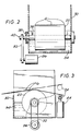
- FIG. 2 is shown a side sectional view of the coloring apparatus in accordance with the invention.
- the coloring apparatus includes a vessel 30 filled with a desired colored ink 34 to a predetermined level.
- the preferred colored ink includes a basic coloring agent NEWFLEX OD C/41 made by SUNCHEMICAL and may be mixed with a solvent that evaporates quickly. Various paints may also be used.
- the coloring roller 22 is a simple rough metal axle with a knurled roller surface.
- the axle 36 is supported by two sealed bearings 38.
- a length 40 of the axle protrudes through the walls of the vessel 30 and beyond the bearings 38.
- a small motor 26 rotates the coloring roller 22 via drive belt 32 connected to the protruding length of the axle.
- the individual ribbons 6 pass transverse to the axial direction of the coloring roller 22 and contact the upper circumference of the coloring roller. When in contact with the coloring roller 22, the colored ink will color one side of the individual ribbons 6 as the coloring roller 22 rotates in colored ink 34.
- rotation of the coloring roller may be controlled.
- control systems for the dyeing and printing of materials are known in the art and are described, e.g. in US Patent No.3,969,779.
- colored ink does not reach the upper portion of the coloring roller circumference and the coloring of the individual ribbons ceases.
- contact roller 24 may be positioned downstream of rough roller 22 and controlled by electromagnetic or pneumatic piston 44 to alter the path of travel of individual ribbons 6.
- piston 44 When piston 44 is retracted, contact roller 24 allows contact between individual ribbons 6 and coloring roller 22.
- contact roller 24 alters the path of travel of individual ribbons 6 thereby preventing contact between the individual ribbons and coloring roller 22. In the extended position, no coloring of the individual ribbons occurs despite continued rotation of the coloring roller.
- Two-sided coloring of the ribbons can be accomplished by repositioning the ribbons so that the ribbons contact the lower circumference of the coloring roller 22.
- an entrance roller 46 and an exit roller 48 are provided at vessel 30 to direct the path of travel of individual ribbons 6 to the underside of coloring roller 22.
- the path of travel of the individual ribbons 6 is directly through the colored ink 34 and in contact with coloring roller 22 thereby coloring both sides of the individual ribbons.
- Electromagnetic or pneumatic piston 46 is provided to raise and lower coloring roller 22 and motor 26 to bring coloring roller 22 in and out of contact with individual ribbons 6.
- the coloring roller when coloring is to be stopped, the coloring roller is raised in order to allow free passage of the individual ribbons. In its raised position individual ribbons 6 travel directly from entrance roller 46 to exit roller 48 without contacting either coloring roller 22 or colored ink 34.
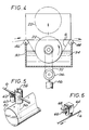
- the coloring apparatus may be implemented utilizing capillary action. As shown in Figure 5, a cylindrical vessel 52 is filled with colored ink 34 to about half its diameter. A thread 56 is held by a thread support 58 located perpendicular to the passage of the individual ribbons 6 and is immersed into the colored ink 34.
- the ribbon 6 As the ribbon 6 passes through the thread support 58, the ribbon contacts the upper portion of the thread 56 which is wet with colored ink because of capillary action. It may be appreciated that a particular advantage of this embodiment is that no moving parts are required for the coloring apparatus itself. If an interruption in coloring is desired, the ribbon 6 is simply moved upward and out of contact with the thread by a pneumatic or electromagnetic cylinder 60 with ribbon guide 62.
- Control of the movement of the above-described rollers and pistons may be obtained via electromagnetic or pneumatic devices as are commonly known in the art and may be maintained under computer programmed control.
- a movement of about 1-3mm is sufficient to break the contact between the coloring device and the individual ribbons. When the ribbons are raised, contact between the coloring device and the individual ribbons is broken and coloring ceases. It will be appreciated that this method and apparatus for producing colored knitted net is extremely versatile and with appropriate control any colored pattern may be created.
- the coloring apparatus may also be implemented using an ink jet printer as shown in Figure 6.
- Ink jet 64 is positioned directly above individual ribbons 6 and is connected via feed line 66 to a colored ink supply and via connection 68 to an appropriate control system.
- An appropriate ink jet printer is ALPHA JET by Metronic Geratebau GmbH & Co. (Germany).
- Ink jet printers create an electrostatic field which moves the ink jet in order to create letters and other complex patterns. For printing on ribbons, however, all that is required is on/off control of the ink jet. Ink jet equipment works very fast creating a printed line 3mm thick at a speed of 600 m/min. At this rate, an ink jet can print by line scanning (similar to a printer wherein the print head moves horizontally and the paper moves vertically) at a rate of about 1.8 sq. m/min. This printing rate is sufficient for coloring oriented ribbons. It will be appreciated that an advantage of this embodiment is that the ribbons which are to be colored may be scanned and colored by the ink jet printer under computer program control, instead of mechanically picking-up the ribbons when the ribbons are not to be colored.
- the ability of having full program control of the position of "jet on” or “jet off” signals allows continuous control as to which (and when) individual ribbons will be colored.
- This particular embodiment may also be implemented with less physical equipment than previously described embodiments.
Landscapes
- Engineering & Computer Science (AREA)
- Textile Engineering (AREA)
- Chemical & Material Sciences (AREA)
- Materials Engineering (AREA)
- Treatment Of Fiber Materials (AREA)
- Woven Fabrics (AREA)
- Braiding, Manufacturing Of Bobbin-Net Or Lace, And Manufacturing Of Nets By Knotting (AREA)
- Knitting Of Fabric (AREA)
- Coloring (AREA)
Description
Claims (20)
- An apparatus for producing knitted net from thermoplastic material comprising a source (2,4) for supplying a plurality of individual oriented thermoplastic ribbons at a constant speed and a knitting apparatus (8) for knitting said plurality of individual oriented thermoplastic ribbons (6) into a net characterised by a colouring apparatus (8) disposed between the source (2,4) and the knitting apparatus (8) including means (22,24,46,60,64) for colouring selected oriented thermoplastic ribbons of the plurality of individual oriented thermoplastic ribbons (6) supplied from the source (2,4).
- An apparatus according to claim 1, characterised in that said plurality of individual ribbons (6) consist essentially of linear low density polyethylene.
- An apparatus according to claim 1 or claim 2 characterised in that said plurality of individual ribbons (6) are produced from a primary film.
- An apparatus according to any preceding claim characterised in that said knitting apparatus (8) is adapted to knit a Raschel net.
- An apparatus according to any preceding claim characterised in that said colouring apparatus is characterised by an ink supply (30) and a colouring roller (22) adapted to apply ink (34) from said ink supply to said selected ribbons (6) of said plurality of individual ribbons.
- An apparatus according to claim 5, characterised by means for controlling rotation of said colouring roller (22).
- An apparatus according to claim 5 or claim 6 further characterised by means for controlling the contact between said colouring roller (22) and said selected ribbons (6) of said plurality of individual ribbons.
- An apparatus according to claim 1, characterised in that said colouring apparatus (8) is characterised by an ink supply (30) and a means (56) for transferring ink from said ink supply (30) to said individual ribbons (6) by capillary action.
- An apparatus according to claim 8, further characterised by means for controlling the application of ink (30) by said means (56) for transferring to said selected ribbons of said plurality of individual ribbons (6).
- An apparatus according to claim 1 wherein said colouring apparatus (8) is characterised by an ink supply (30) and an ink jet (64) for applying ink from said ink supply to said selected ribbons of said plurality of individual ribbons (6).
- An apparatus according to claim 10 characterised by means for controlling the operation of said ink jet (64).
- A method of producing knitted net from thermoplastic material comprising the steps of supplying a plurality of individual oriented thermoplastic ribbons (6) at constant speed and knitting them into a net characterised by the step of colouring selected oriented thermoplastic ribbons of the plurality of individual oriented thermoplastic ribbons (6) supplied from the source before knitting them into the net.
- A method according to claim 12 further characterised by the step of knitting the plurality of individual ribbons into a Raschel net.
- A method according to claim 12 or claim 13 further characterised by the step of applying ink from an ink supply to the selected ribbons of the plurality of individual ribbons with a colouring roller.
- A method according to claim 14 further characterised by the step of controlling the rotation of the colouring roller.
- A method according to claim 14 or claim 15 further characterised by the step of controlling contact between the colouring roller and the selected ribbons of the plurality of individual ribbons.
- A method according to claim 12 or claim 13 further characterised by the step of transferring ink from an ink supply to the selected ribbons of the plurality of individual ribbons by capillary action.
- A method according to claim 17, further characterised by the step of controlling the transfer of ink between the ink supply and the selected ribbons of the plurality of individual ribbons.
- A method according to claim 12 or claim 13 further characterised by the step of applying ink from an ink supply to the selected ribbons of the plurality of individual ribbons by an ink jet.
- A method according to claim 19 further characterised by the step of controlling the operation of the ink jet.
Applications Claiming Priority (2)
| Application Number | Priority Date | Filing Date | Title |
|---|---|---|---|
| US91119492A | 1992-07-09 | 1992-07-09 | |
| US911194 | 1992-07-09 |
Publications (2)
| Publication Number | Publication Date |
|---|---|
| EP0578353A1 EP0578353A1 (en) | 1994-01-12 |
| EP0578353B1 true EP0578353B1 (en) | 1998-11-11 |
Family
ID=25429889
Family Applications (1)
| Application Number | Title | Priority Date | Filing Date |
|---|---|---|---|
| EP19930303160 Expired - Lifetime EP0578353B1 (en) | 1992-07-09 | 1993-04-22 | Apparatus and method for producing coloured knitted net |
Country Status (6)
| Country | Link |
|---|---|
| EP (1) | EP0578353B1 (en) |
| AU (1) | AU666359B2 (en) |
| CA (1) | CA2095296C (en) |
| DE (1) | DE69322003T2 (en) |
| ES (1) | ES2125949T3 (en) |
| NZ (1) | NZ247432A (en) |
Families Citing this family (5)
| Publication number | Priority date | Publication date | Assignee | Title |
|---|---|---|---|---|
| DE602004016056D1 (en) * | 2004-09-07 | 2008-10-02 | Tama Plastic Ind | NETWORK MATERIAL WITH REFLECTIVE OR LUMINESCENT MARKING MATERIAL |
| GR1005797B (en) * | 2006-03-09 | 2008-01-30 | ������������ ������������� ������������ �.�. | Manufacturing of nets from synthetic fibers and mihina |
| EP1845182B1 (en) * | 2006-04-11 | 2008-10-15 | KARL MAYER TEXTILMASCHINENFABRIK GmbH | Warp-knitting machine |
| CN110936388B (en) * | 2019-12-06 | 2021-06-11 | 塑晟机械(嘉兴)有限公司 | Full-automatic hosiery machine sock blank transferring arm mechanism and transferring method thereof |
| CN114223408B (en) * | 2022-01-21 | 2025-06-27 | 内蒙古工业大学 | A towed alfalfa baler with microwave drying function |
Family Cites Families (11)
| Publication number | Priority date | Publication date | Assignee | Title |
|---|---|---|---|---|
| GB318840A (en) * | 1928-09-08 | 1930-12-09 | British Celanese | Improvements in or relating to textile fabrics |
| GB398191A (en) * | 1932-03-07 | 1933-09-07 | British Celanese | Improvements in the treatment of filamentary textile materials |
| DE6936578U (en) * | 1969-09-17 | 1970-01-29 | Schlayer Polydress Gmbh Fa | TEXTILE RAIL, IN PARTICULAR FOR THE MANUFACTURE OF PACKAGING CASES |
| BE755182A (en) * | 1969-09-24 | 1971-02-01 | Belloli Luigi | CONTINUOUS FABRIC MANUFACTURING METHOD, APPARATUS APPLYING THIS METHOD AND FABRICS SO OBTAINED |
| US3769815A (en) * | 1970-12-14 | 1973-11-06 | Forsch Textiltechnologe | Method of producing textiles on knitting machines |
| US3952552A (en) * | 1972-09-29 | 1976-04-27 | C.J.I. Industries, Inc. | Auxiliary yarn dyeing mechanism |
| US3969779A (en) * | 1974-07-30 | 1976-07-20 | Deering Milliken Research Corporation | Dyeing and printing of materials |
| DE2437918A1 (en) * | 1974-08-07 | 1976-02-19 | Bayer Ag | Knitting yarn dyeing process - with dyestuff fed to yarn as it is formed into stitches by the knitter |
| US4060999A (en) * | 1974-11-05 | 1977-12-06 | Enterprise Incorporated | Method and apparatus for forming yarn elements and producing products therefrom |
| US4015550A (en) * | 1975-08-12 | 1977-04-05 | West Point Pepperell, Inc. | Apparatus and method for selective multi-color dyeing of individual yarns and producing therefrom a predetermined complex design in a tufted carpet |
| US4068502A (en) * | 1976-08-06 | 1978-01-17 | Harald Anderson | Apparatus for multicolor dyeing of textile yarns |
-
1993
- 1993-04-19 NZ NZ24743293A patent/NZ247432A/en unknown
- 1993-04-22 EP EP19930303160 patent/EP0578353B1/en not_active Expired - Lifetime
- 1993-04-22 ES ES93303160T patent/ES2125949T3/en not_active Expired - Lifetime
- 1993-04-22 DE DE1993622003 patent/DE69322003T2/en not_active Expired - Fee Related
- 1993-04-27 AU AU37193/93A patent/AU666359B2/en not_active Ceased
- 1993-04-30 CA CA 2095296 patent/CA2095296C/en not_active Expired - Fee Related
Also Published As
| Publication number | Publication date |
|---|---|
| CA2095296A1 (en) | 1994-01-10 |
| DE69322003D1 (en) | 1998-12-17 |
| AU666359B2 (en) | 1996-02-08 |
| CA2095296C (en) | 2000-11-21 |
| EP0578353A1 (en) | 1994-01-12 |
| NZ247432A (en) | 1994-10-26 |
| ES2125949T3 (en) | 1999-03-16 |
| AU3719393A (en) | 1994-01-20 |
| DE69322003T2 (en) | 1999-04-29 |
Similar Documents
| Publication | Publication Date | Title |
|---|---|---|
| DE3850741T2 (en) | Thermal ribbon feed device. | |
| DE69901806T2 (en) | PRINT TEXTIEL WITH AN INK JET PRINTER | |
| DE69616752T2 (en) | PRINTING DEVICE AND PRINTING METHOD | |
| DE69705855T2 (en) | STRIP PRINTING DEVICE | |
| DE69310764T2 (en) | Printer with feed error detector | |
| DE3928732C2 (en) | Ink jet recorder | |
| DE69612602T2 (en) | Inkjet device with hot-melt ink for shading marking for use in automatic fabric laying devices | |
| DE19810585A1 (en) | Method and device for processing strip material | |
| DE2631553B2 (en) | Process for the sharp contours of a web of material by spraying on paint as well as equipment and spray nozzle for carrying out the process | |
| DE69111284T2 (en) | Printing device. | |
| DE3103935A1 (en) | METHOD AND THERMAL PRINTER FOR PRINTING LABELS AND THE RELATED LABEL | |
| DE68922482T2 (en) | Laying device for rubberized sheets. | |
| EP0132727A1 (en) | Device for automatically cutting and winding webs | |
| DE19517436A1 (en) | Color thermal printer with highly accurate dye ribbon positioning | |
| DE69626897T2 (en) | Method and device for partially dyeing yarn | |
| CA2095296C (en) | Apparatus and method for producing colored knitted net | |
| EP0063371B1 (en) | Knitting machine for the production of a striped fabric | |
| US5664306A (en) | Apparatus and method for producing colored knitted net | |
| DE3883108T2 (en) | THERMOGRAPHY MATERIAL AND THEIR PRODUCTION. | |
| DE2843361C2 (en) | ||
| JP2003342867A (en) | Method for top-dyeing of yarn and dyeing apparatus | |
| DE69709809T2 (en) | PRINTING | |
| DE69305898T2 (en) | Packaging machine with thermal printer | |
| DE69120144T2 (en) | Method and device for heating textile materials by treatment agents | |
| DE69205213T2 (en) | Device for feeding an endless plastic film. |
Legal Events
| Date | Code | Title | Description |
|---|---|---|---|
| PUAI | Public reference made under article 153(3) epc to a published international application that has entered the european phase |
Free format text: ORIGINAL CODE: 0009012 |
|
| AK | Designated contracting states |
Kind code of ref document: A1 Designated state(s): DE ES FR GB IT PT SE |
|
| 17P | Request for examination filed |
Effective date: 19940603 |
|
| 17Q | First examination report despatched |
Effective date: 19960223 |
|
| GRAG | Despatch of communication of intention to grant |
Free format text: ORIGINAL CODE: EPIDOS AGRA |
|
| GRAG | Despatch of communication of intention to grant |
Free format text: ORIGINAL CODE: EPIDOS AGRA |
|
| GRAH | Despatch of communication of intention to grant a patent |
Free format text: ORIGINAL CODE: EPIDOS IGRA |
|
| GRAH | Despatch of communication of intention to grant a patent |
Free format text: ORIGINAL CODE: EPIDOS IGRA |
|
| GRAA | (expected) grant |
Free format text: ORIGINAL CODE: 0009210 |
|
| AK | Designated contracting states |
Kind code of ref document: B1 Designated state(s): DE ES FR GB IT PT SE |
|
| REF | Corresponds to: |
Ref document number: 69322003 Country of ref document: DE Date of ref document: 19981217 |
|
| ET | Fr: translation filed | ||
| ITF | It: translation for a ep patent filed | ||
| REG | Reference to a national code |
Ref country code: ES Ref legal event code: FG2A Ref document number: 2125949 Country of ref document: ES Kind code of ref document: T3 |
|
| REG | Reference to a national code |
Ref country code: PT Ref legal event code: SC4A Free format text: AVAILABILITY OF NATIONAL TRANSLATION Effective date: 19981209 |
|
| PLBE | No opposition filed within time limit |
Free format text: ORIGINAL CODE: 0009261 |
|
| STAA | Information on the status of an ep patent application or granted ep patent |
Free format text: STATUS: NO OPPOSITION FILED WITHIN TIME LIMIT |
|
| 26N | No opposition filed | ||
| REG | Reference to a national code |
Ref country code: GB Ref legal event code: IF02 |
|
| PGFP | Annual fee paid to national office [announced via postgrant information from national office to epo] |
Ref country code: PT Payment date: 20030410 Year of fee payment: 11 |
|
| PGFP | Annual fee paid to national office [announced via postgrant information from national office to epo] |
Ref country code: GB Payment date: 20030416 Year of fee payment: 11 |
|
| PGFP | Annual fee paid to national office [announced via postgrant information from national office to epo] |
Ref country code: FR Payment date: 20030418 Year of fee payment: 11 |
|
| PGFP | Annual fee paid to national office [announced via postgrant information from national office to epo] |
Ref country code: SE Payment date: 20030422 Year of fee payment: 11 |
|
| PGFP | Annual fee paid to national office [announced via postgrant information from national office to epo] |
Ref country code: DE Payment date: 20030430 Year of fee payment: 11 |
|
| PGFP | Annual fee paid to national office [announced via postgrant information from national office to epo] |
Ref country code: ES Payment date: 20030508 Year of fee payment: 11 |
|
| PG25 | Lapsed in a contracting state [announced via postgrant information from national office to epo] |
Ref country code: GB Free format text: LAPSE BECAUSE OF NON-PAYMENT OF DUE FEES Effective date: 20040422 |
|
| PG25 | Lapsed in a contracting state [announced via postgrant information from national office to epo] |
Ref country code: SE Free format text: LAPSE BECAUSE OF NON-PAYMENT OF DUE FEES Effective date: 20040423 Ref country code: ES Free format text: LAPSE BECAUSE OF NON-PAYMENT OF DUE FEES Effective date: 20040423 |
|
| PG25 | Lapsed in a contracting state [announced via postgrant information from national office to epo] |
Ref country code: PT Free format text: LAPSE BECAUSE OF NON-PAYMENT OF DUE FEES Effective date: 20041022 |
|
| PG25 | Lapsed in a contracting state [announced via postgrant information from national office to epo] |
Ref country code: DE Free format text: LAPSE BECAUSE OF NON-PAYMENT OF DUE FEES Effective date: 20041103 |
|
| EUG | Se: european patent has lapsed | ||
| GBPC | Gb: european patent ceased through non-payment of renewal fee |
Effective date: 20040422 |
|
| PG25 | Lapsed in a contracting state [announced via postgrant information from national office to epo] |
Ref country code: FR Free format text: LAPSE BECAUSE OF NON-PAYMENT OF DUE FEES Effective date: 20041231 |
|
| REG | Reference to a national code |
Ref country code: PT Ref legal event code: MM4A Free format text: LAPSE DUE TO NON-PAYMENT OF FEES Effective date: 20041022 |
|
| REG | Reference to a national code |
Ref country code: FR Ref legal event code: ST |
|
| PG25 | Lapsed in a contracting state [announced via postgrant information from national office to epo] |
Ref country code: IT Free format text: LAPSE BECAUSE OF NON-PAYMENT OF DUE FEES;WARNING: LAPSES OF ITALIAN PATENTS WITH EFFECTIVE DATE BEFORE 2007 MAY HAVE OCCURRED AT ANY TIME BEFORE 2007. THE CORRECT EFFECTIVE DATE MAY BE DIFFERENT FROM THE ONE RECORDED. Effective date: 20050422 |
|
| REG | Reference to a national code |
Ref country code: ES Ref legal event code: FD2A Effective date: 20040423 |