EP0578347B1 - Separation of metal ions on an anion exchange resin by chromatographic elution - Google Patents
Separation of metal ions on an anion exchange resin by chromatographic elution Download PDFInfo
- Publication number
- EP0578347B1 EP0578347B1 EP93301564A EP93301564A EP0578347B1 EP 0578347 B1 EP0578347 B1 EP 0578347B1 EP 93301564 A EP93301564 A EP 93301564A EP 93301564 A EP93301564 A EP 93301564A EP 0578347 B1 EP0578347 B1 EP 0578347B1
- Authority
- EP
- European Patent Office
- Prior art keywords
- column
- solution
- metal
- resin
- complexes
- Prior art date
- Legal status (The legal status is an assumption and is not a legal conclusion. Google has not performed a legal analysis and makes no representation as to the accuracy of the status listed.)
- Expired - Lifetime
Links
- 229910021645 metal ion Inorganic materials 0.000 title claims abstract description 52
- 238000000926 separation method Methods 0.000 title claims abstract description 29
- 239000003957 anion exchange resin Substances 0.000 title claims abstract description 27
- 238000010828 elution Methods 0.000 title claims abstract description 20
- 229910052751 metal Inorganic materials 0.000 claims abstract description 111
- 239000002184 metal Substances 0.000 claims abstract description 111
- 238000010494 dissociation reaction Methods 0.000 claims abstract description 24
- 230000005593 dissociations Effects 0.000 claims abstract description 24
- 125000000129 anionic group Chemical group 0.000 claims abstract description 11
- 239000000356 contaminant Substances 0.000 claims abstract description 8
- 230000000694 effects Effects 0.000 claims abstract description 5
- 150000004696 coordination complex Chemical class 0.000 claims abstract 2
- 239000000243 solution Substances 0.000 claims description 137
- 239000011347 resin Substances 0.000 claims description 78
- 229920005989 resin Polymers 0.000 claims description 78
- VEXZGXHMUGYJMC-UHFFFAOYSA-N Hydrochloric acid Chemical compound Cl VEXZGXHMUGYJMC-UHFFFAOYSA-N 0.000 claims description 53
- 238000000034 method Methods 0.000 claims description 47
- XEEYBQQBJWHFJM-UHFFFAOYSA-N Iron Chemical compound [Fe] XEEYBQQBJWHFJM-UHFFFAOYSA-N 0.000 claims description 46
- 239000011701 zinc Substances 0.000 claims description 41
- 239000002253 acid Substances 0.000 claims description 38
- 238000011068 loading method Methods 0.000 claims description 37
- XLYOFNOQVPJJNP-UHFFFAOYSA-N water Substances O XLYOFNOQVPJJNP-UHFFFAOYSA-N 0.000 claims description 36
- 150000002739 metals Chemical class 0.000 claims description 32
- 239000012530 fluid Substances 0.000 claims description 27
- 230000000536 complexating effect Effects 0.000 claims description 25
- 229910052725 zinc Inorganic materials 0.000 claims description 19
- HCHKCACWOHOZIP-UHFFFAOYSA-N Zinc Chemical compound [Zn] HCHKCACWOHOZIP-UHFFFAOYSA-N 0.000 claims description 18
- 229910052742 iron Inorganic materials 0.000 claims description 15
- 229910052793 cadmium Inorganic materials 0.000 claims description 13
- BDOSMKKIYDKNTQ-UHFFFAOYSA-N cadmium atom Chemical compound [Cd] BDOSMKKIYDKNTQ-UHFFFAOYSA-N 0.000 claims description 13
- 239000011651 chromium Substances 0.000 claims description 13
- 238000012545 processing Methods 0.000 claims description 12
- 239000003085 diluting agent Substances 0.000 claims description 10
- NWUYHJFMYQTDRP-UHFFFAOYSA-N 1,2-bis(ethenyl)benzene;1-ethenyl-2-ethylbenzene;styrene Chemical compound C=CC1=CC=CC=C1.CCC1=CC=CC=C1C=C.C=CC1=CC=CC=C1C=C NWUYHJFMYQTDRP-UHFFFAOYSA-N 0.000 claims description 9
- RYGMFSIKBFXOCR-UHFFFAOYSA-N Copper Chemical compound [Cu] RYGMFSIKBFXOCR-UHFFFAOYSA-N 0.000 claims description 9
- 229910052802 copper Inorganic materials 0.000 claims description 9
- 239000010949 copper Substances 0.000 claims description 9
- 239000003456 ion exchange resin Substances 0.000 claims description 9
- 229920003303 ion-exchange polymer Polymers 0.000 claims description 9
- 150000002500 ions Chemical class 0.000 claims description 9
- 239000008139 complexing agent Substances 0.000 claims description 8
- PXHVJJICTQNCMI-UHFFFAOYSA-N Nickel Chemical compound [Ni] PXHVJJICTQNCMI-UHFFFAOYSA-N 0.000 claims description 7
- 229910052804 chromium Inorganic materials 0.000 claims description 7
- VYZAMTAEIAYCRO-UHFFFAOYSA-N Chromium Chemical compound [Cr] VYZAMTAEIAYCRO-UHFFFAOYSA-N 0.000 claims description 6
- KRHYYFGTRYWZRS-UHFFFAOYSA-N Fluorane Chemical compound F KRHYYFGTRYWZRS-UHFFFAOYSA-N 0.000 claims description 6
- 239000011133 lead Substances 0.000 claims description 5
- 238000003860 storage Methods 0.000 claims description 5
- 239000002699 waste material Substances 0.000 claims description 5
- 238000011144 upstream manufacturing Methods 0.000 claims description 4
- BMYNFMYTOJXKLE-UHFFFAOYSA-N 3-azaniumyl-2-hydroxypropanoate Chemical compound NCC(O)C(O)=O BMYNFMYTOJXKLE-UHFFFAOYSA-N 0.000 claims description 3
- VEXZGXHMUGYJMC-UHFFFAOYSA-M Chloride anion Chemical compound [Cl-] VEXZGXHMUGYJMC-UHFFFAOYSA-M 0.000 claims description 3
- XMBWDFGMSWQBCA-UHFFFAOYSA-N hydrogen iodide Chemical compound I XMBWDFGMSWQBCA-UHFFFAOYSA-N 0.000 claims description 3
- 229940071870 hydroiodic acid Drugs 0.000 claims description 3
- 238000002156 mixing Methods 0.000 claims description 3
- 239000011135 tin Substances 0.000 claims description 3
- ATJFFYVFTNAWJD-UHFFFAOYSA-N Tin Chemical compound [Sn] ATJFFYVFTNAWJD-UHFFFAOYSA-N 0.000 claims description 2
- 238000013375 chromatographic separation Methods 0.000 claims description 2
- PCHJSUWPFVWCPO-UHFFFAOYSA-N gold Chemical compound [Au] PCHJSUWPFVWCPO-UHFFFAOYSA-N 0.000 claims description 2
- 229910052737 gold Inorganic materials 0.000 claims description 2
- 239000010931 gold Substances 0.000 claims description 2
- QSHDDOUJBYECFT-UHFFFAOYSA-N mercury Chemical compound [Hg] QSHDDOUJBYECFT-UHFFFAOYSA-N 0.000 claims description 2
- 229910052753 mercury Inorganic materials 0.000 claims description 2
- 229910052759 nickel Inorganic materials 0.000 claims description 2
- 238000001223 reverse osmosis Methods 0.000 claims description 2
- 150000003839 salts Chemical class 0.000 claims description 2
- 229910052709 silver Inorganic materials 0.000 claims description 2
- 239000004332 silver Substances 0.000 claims description 2
- 229910052718 tin Inorganic materials 0.000 claims description 2
- 239000012527 feed solution Substances 0.000 claims 2
- 230000007704 transition Effects 0.000 claims 2
- 238000002242 deionisation method Methods 0.000 claims 1
- 238000005246 galvanizing Methods 0.000 claims 1
- 238000005554 pickling Methods 0.000 claims 1
- 238000000746 purification Methods 0.000 abstract description 2
- YKYOUMDCQGMQQO-UHFFFAOYSA-L cadmium dichloride Chemical compound Cl[Cd]Cl YKYOUMDCQGMQQO-UHFFFAOYSA-L 0.000 description 14
- 239000008367 deionised water Substances 0.000 description 14
- 229910021641 deionized water Inorganic materials 0.000 description 14
- 125000001309 chloro group Chemical group Cl* 0.000 description 13
- 238000011084 recovery Methods 0.000 description 12
- VTLYFUHAOXGGBS-UHFFFAOYSA-N Fe3+ Chemical compound [Fe+3] VTLYFUHAOXGGBS-UHFFFAOYSA-N 0.000 description 9
- 229910001447 ferric ion Inorganic materials 0.000 description 9
- 229910021578 Iron(III) chloride Inorganic materials 0.000 description 8
- RBTARNINKXHZNM-UHFFFAOYSA-K iron trichloride Chemical compound Cl[Fe](Cl)Cl RBTARNINKXHZNM-UHFFFAOYSA-K 0.000 description 8
- 239000000203 mixture Substances 0.000 description 7
- -1 cadium Chemical compound 0.000 description 6
- 238000007747 plating Methods 0.000 description 6
- 239000011592 zinc chloride Substances 0.000 description 6
- JIAARYAFYJHUJI-UHFFFAOYSA-L zinc dichloride Chemical compound [Cl-].[Cl-].[Zn+2] JIAARYAFYJHUJI-UHFFFAOYSA-L 0.000 description 6
- 238000005341 cation exchange Methods 0.000 description 5
- 238000009792 diffusion process Methods 0.000 description 5
- 238000005342 ion exchange Methods 0.000 description 5
- 231100000331 toxic Toxicity 0.000 description 5
- 230000002588 toxic effect Effects 0.000 description 5
- OKTJSMMVPCPJKN-UHFFFAOYSA-N Carbon Chemical compound [C] OKTJSMMVPCPJKN-UHFFFAOYSA-N 0.000 description 4
- 238000009826 distribution Methods 0.000 description 4
- 238000004519 manufacturing process Methods 0.000 description 4
- 239000012071 phase Substances 0.000 description 4
- 229910052761 rare earth metal Inorganic materials 0.000 description 4
- CWYNVVGOOAEACU-UHFFFAOYSA-N Fe2+ Chemical compound [Fe+2] CWYNVVGOOAEACU-UHFFFAOYSA-N 0.000 description 3
- HEMHJVSKTPXQMS-UHFFFAOYSA-M Sodium hydroxide Chemical compound [OH-].[Na+] HEMHJVSKTPXQMS-UHFFFAOYSA-M 0.000 description 3
- 150000001450 anions Chemical class 0.000 description 3
- 239000008346 aqueous phase Substances 0.000 description 3
- 230000015572 biosynthetic process Effects 0.000 description 3
- 229910001448 ferrous ion Inorganic materials 0.000 description 3
- 229910001385 heavy metal Inorganic materials 0.000 description 3
- 229910000000 metal hydroxide Inorganic materials 0.000 description 3
- 150000004692 metal hydroxides Chemical class 0.000 description 3
- 238000000638 solvent extraction Methods 0.000 description 3
- 239000000126 substance Substances 0.000 description 3
- 239000010891 toxic waste Substances 0.000 description 3
- 239000002351 wastewater Substances 0.000 description 3
- 229910017518 Cu Zn Inorganic materials 0.000 description 2
- 239000012190 activator Substances 0.000 description 2
- 238000005349 anion exchange Methods 0.000 description 2
- 238000004140 cleaning Methods 0.000 description 2
- 238000010790 dilution Methods 0.000 description 2
- 239000012895 dilution Substances 0.000 description 2
- 239000003657 drainage water Substances 0.000 description 2
- 238000009713 electroplating Methods 0.000 description 2
- 238000001704 evaporation Methods 0.000 description 2
- 230000008020 evaporation Effects 0.000 description 2
- 239000004519 grease Substances 0.000 description 2
- 239000012500 ion exchange media Substances 0.000 description 2
- 239000000463 material Substances 0.000 description 2
- 239000008041 oiling agent Substances 0.000 description 2
- 150000002894 organic compounds Chemical class 0.000 description 2
- 239000002245 particle Substances 0.000 description 2
- 238000004886 process control Methods 0.000 description 2
- 239000000047 product Substances 0.000 description 2
- 239000012492 regenerant Substances 0.000 description 2
- 239000012508 resin bead Substances 0.000 description 2
- 230000000717 retained effect Effects 0.000 description 2
- 238000001179 sorption measurement Methods 0.000 description 2
- 239000000080 wetting agent Substances 0.000 description 2
- 229910021592 Copper(II) chloride Inorganic materials 0.000 description 1
- 101100412856 Mus musculus Rhod gene Proteins 0.000 description 1
- BQCADISMDOOEFD-UHFFFAOYSA-N Silver Chemical compound [Ag] BQCADISMDOOEFD-UHFFFAOYSA-N 0.000 description 1
- 238000003914 acid mine drainage Methods 0.000 description 1
- 230000002378 acidificating effect Effects 0.000 description 1
- 230000000740 bleeding effect Effects 0.000 description 1
- 239000003729 cation exchange resin Substances 0.000 description 1
- 229940023913 cation exchange resins Drugs 0.000 description 1
- 150000001768 cations Chemical class 0.000 description 1
- 229920001429 chelating resin Polymers 0.000 description 1
- 238000006243 chemical reaction Methods 0.000 description 1
- 239000003795 chemical substances by application Substances 0.000 description 1
- 229910001430 chromium ion Inorganic materials 0.000 description 1
- 230000001143 conditioned effect Effects 0.000 description 1
- ORTQZVOHEJQUHG-UHFFFAOYSA-L copper(II) chloride Chemical compound Cl[Cu]Cl ORTQZVOHEJQUHG-UHFFFAOYSA-L 0.000 description 1
- 238000000354 decomposition reaction Methods 0.000 description 1
- 230000001419 dependent effect Effects 0.000 description 1
- 238000001514 detection method Methods 0.000 description 1
- 239000012153 distilled water Substances 0.000 description 1
- 238000005516 engineering process Methods 0.000 description 1
- 238000011090 industrial biotechnology method and process Methods 0.000 description 1
- 239000010842 industrial wastewater Substances 0.000 description 1
- 229910052500 inorganic mineral Inorganic materials 0.000 description 1
- 238000009434 installation Methods 0.000 description 1
- 229910001510 metal chloride Inorganic materials 0.000 description 1
- 239000011707 mineral Substances 0.000 description 1
- 235000010755 mineral Nutrition 0.000 description 1
- 238000005065 mining Methods 0.000 description 1
- 238000006386 neutralization reaction Methods 0.000 description 1
- 230000003472 neutralizing effect Effects 0.000 description 1
- 230000003287 optical effect Effects 0.000 description 1
- 230000033116 oxidation-reduction process Effects 0.000 description 1
- 239000002244 precipitate Substances 0.000 description 1
- 238000001556 precipitation Methods 0.000 description 1
- 230000002028 premature Effects 0.000 description 1
- 238000005086 pumping Methods 0.000 description 1
- 150000002910 rare earth metals Chemical class 0.000 description 1
- 230000008929 regeneration Effects 0.000 description 1
- 238000011069 regeneration method Methods 0.000 description 1
- 238000012958 reprocessing Methods 0.000 description 1
- 230000035945 sensitivity Effects 0.000 description 1
- 239000002002 slurry Substances 0.000 description 1
- MNWBNISUBARLIT-UHFFFAOYSA-N sodium cyanide Chemical compound [Na+].N#[C-] MNWBNISUBARLIT-UHFFFAOYSA-N 0.000 description 1
- 239000008399 tap water Substances 0.000 description 1
- 235000020679 tap water Nutrition 0.000 description 1
- 229910052723 transition metal Inorganic materials 0.000 description 1
- 229910001428 transition metal ion Inorganic materials 0.000 description 1
- 238000013022 venting Methods 0.000 description 1
- 230000000007 visual effect Effects 0.000 description 1
- 238000004065 wastewater treatment Methods 0.000 description 1
- 238000004876 x-ray fluorescence Methods 0.000 description 1
Images




Classifications
-
- B—PERFORMING OPERATIONS; TRANSPORTING
- B01—PHYSICAL OR CHEMICAL PROCESSES OR APPARATUS IN GENERAL
- B01D—SEPARATION
- B01D15/00—Separating processes involving the treatment of liquids with solid sorbents; Apparatus therefor
- B01D15/08—Selective adsorption, e.g. chromatography
- B01D15/26—Selective adsorption, e.g. chromatography characterised by the separation mechanism
- B01D15/36—Selective adsorption, e.g. chromatography characterised by the separation mechanism involving ionic interaction, e.g. ion-exchange, ion-pair, ion-suppression or ion-exclusion
- B01D15/361—Ion-exchange
- B01D15/363—Anion-exchange
-
- B—PERFORMING OPERATIONS; TRANSPORTING
- B01—PHYSICAL OR CHEMICAL PROCESSES OR APPARATUS IN GENERAL
- B01J—CHEMICAL OR PHYSICAL PROCESSES, e.g. CATALYSIS OR COLLOID CHEMISTRY; THEIR RELEVANT APPARATUS
- B01J41/00—Anion exchange; Use of material as anion exchangers; Treatment of material for improving the anion exchange properties
- B01J41/20—Anion exchangers for chromatographic processes
-
- B—PERFORMING OPERATIONS; TRANSPORTING
- B01—PHYSICAL OR CHEMICAL PROCESSES OR APPARATUS IN GENERAL
- B01J—CHEMICAL OR PHYSICAL PROCESSES, e.g. CATALYSIS OR COLLOID CHEMISTRY; THEIR RELEVANT APPARATUS
- B01J45/00—Ion-exchange in which a complex or a chelate is formed; Use of material as complex or chelate forming ion-exchangers; Treatment of material for improving the complex or chelate forming ion-exchange properties
-
- C—CHEMISTRY; METALLURGY
- C22—METALLURGY; FERROUS OR NON-FERROUS ALLOYS; TREATMENT OF ALLOYS OR NON-FERROUS METALS
- C22B—PRODUCTION AND REFINING OF METALS; PRETREATMENT OF RAW MATERIALS
- C22B3/00—Extraction of metal compounds from ores or concentrates by wet processes
- C22B3/20—Treatment or purification of solutions, e.g. obtained by leaching
- C22B3/42—Treatment or purification of solutions, e.g. obtained by leaching by ion-exchange extraction
-
- Y—GENERAL TAGGING OF NEW TECHNOLOGICAL DEVELOPMENTS; GENERAL TAGGING OF CROSS-SECTIONAL TECHNOLOGIES SPANNING OVER SEVERAL SECTIONS OF THE IPC; TECHNICAL SUBJECTS COVERED BY FORMER USPC CROSS-REFERENCE ART COLLECTIONS [XRACs] AND DIGESTS
- Y02—TECHNOLOGIES OR APPLICATIONS FOR MITIGATION OR ADAPTATION AGAINST CLIMATE CHANGE
- Y02P—CLIMATE CHANGE MITIGATION TECHNOLOGIES IN THE PRODUCTION OR PROCESSING OF GOODS
- Y02P10/00—Technologies related to metal processing
- Y02P10/20—Recycling
Definitions
- the present invention relates to the separation of metal ion contaminants from a variety of sources, such as, for example, spent stripper and activator plating solutions which are adsorbed on an anion exchange resin in the form of their anionic complexes and to the recovery, separation and purification of the metals by chromatographic elution.
- Waste HC1 acid solutions (usually 2-5 M) containing toxic metals such as chromium, lead, copper, cadium, etc. are classified as toxic waste. These solutions can come from a number of sources including the electroplating industry, the manufacture of printed circuit boards, the regeneration of cation exchange resins used in cleaning waste waters (including acidic mine drainage water), etc.
- the most common treatment practice for these toxic solutions in use is neutralization and precipitation which produces insoluble metal hydroxides; this method is costly because the neutralizing agent, usually sodium hydroxide, is relatively expensive.
- These solutions must then be replaced with new acid at additional expense.
- Another disadvantage is that the precipitated slurry consists of a mixture of metal hydroxides that has to be disposed of in designated toxic landfills. The disposal costs have been and will continue to rise due to tightening restrictions from the "Land Ban Act.” Further, this practice does not stop the generators future liability should problems develop in the disposal facility.
- the present invention generally refers to a process for the removal of anionic metal complexes from complexating solutions (i.e., HCl, HF, NaCN, etc.)
- complexating solutions i.e., HCl, HF, NaCN, etc.
- anion exchange resin to absorb said metal complexes thereon, which comprises selectively removing the metals therefrom by chromatographic elution, whereby the complexing ion concentration is gradually reduced causing the individual metal complexes to break: down as determined by their respective dissociation constants and thus come off of the anion exchange resin in reverse order of the dissociation constants of the individual anionic complexes, effectively separating one from the other.
- the present invention provides a process for removing metal ions from a solution containing said metal ions as complexes having respective dissociation constants that differ from one another and then separating said metal ions from one another, which process comprises the steps of:
- apparatus for the chromatographic separation of a plurality of metal ions present as metal ion complexes in a complexing acid solution comprising a chromatographic column having an input at one end for receiving a fluid to be processed therein, an output at the opposite end thereof for withdrawing fluid therefrom, a first processing chamber intermediate the input and output ends suitable for containing a first bed of anion exchange resin in the dominant flow path of a fluid passing from the input toward the output of said column, a second processing chamber intermediate the first processing chamber and the output end of said column suitable for containing a second bed of ion exchange resin in said dominant flow path, input flow control means for selectively controlling the flow of first and second fluids introduced into the input end of said column, a source of said complexing solution coupled to said first fluid input control means, a source of water coupled to said second fluid input control means, output flow control means for selectively controlling the flow of fluid out of the output of said column, and a sensor for observing a sample
- the finishing column ordinarily being greater than 4 inches (10.2cms) in length, about 30 inches (76.2cms) being the preferred
- the flow velocity of the eluting solution is between about 0.5 gallons per minute per square foot of column cross sectional area (0.5 gpm/ft 2 )-0.34 litres per second per square metre of column cross sectional area (0.34 LPS/m 2 ) and 5 gpm/ft 2 (3.4 LPS/m 2 ), the preferred flow velocity is about 1.7 gpm/ft 2 (1.16 lps/m 2 )at 20°C;
- the temperature of the eluting solution is between about 0°C to 80°C;
- the anion-exchange resin is a macroporous strong basic type I or II anion resin for higher flow velocities and a gel type strong basic resin for very
- the present invention is based upon the discovery that it is possible to separate the metals loaded on the resins that are usually found in spent hydrochloric acid plating solutions as their chloro complexes, such metals being iron, zinc and cadmium, into eluates rich in an individual metal.
- the eluted fractions can be sold to the chemical industry either as solutions containing the individual metal ions, as precipitates of individual metal hydroxides or as the electrolytically recovered metal itself.
- the present invention is applicable not only to spent plating solutions as hereinbefore described, but may also be applied with equal facility to other areas besides the metal finishing industry as well as other complexing systems.
- ion exchange processes are used to extract the metal ions from the water.
- the resin is then regenerated with hydrochloric acid which becomes contaminated with iron, zinc, copper, cadmium and other toxic metals that are present in the waste water.
- This acid can be treated with the present process and in the same manner as other waste hydrochloric acid.
- Another application of the present invention is in the separation of rare earth elements.
- Current technology loads these elements on an anion exchange resin as their chloro complexes and then elutes them by passing different solutions through the columns that contain different quantities of chloride ions.
- Using the chromatographic process of this invention only one instead of multiple elution solutions are needed and the total amount of elution solution is substantially reduced. Additionally, the time required for elution is greatly reduced and, accordingly, operating costs are significantly lower. Recovering separated metal ions from any process that allows transition metal ions or rare earth metal ions to be loaded on an anion exchange resin as chloro complexes can be improved by the presently described process and integrally necessary apparatus.
- the metals that are usually found in spent hydrochloric acid stripping solutions for example, as their chloro complexes are ([M n+ Cl x ] y- ), where M n+ is Fe 3+ , Zn 2+ and Cd 2+ .
- the chloride ion concentration in the aqueous phase and hence, the molarity of the hydrochloric acid in the aqueous phase has a profound influence on the separability of these chloro complexes.
- the formation constants of the chloro complexes decrease in the following sequence: Cd 2+ > Zn 2+ > Fe 3+ .
- Cd 2+ > Zn 2+ > Fe 3+ On the basis of the equilibria involved, it is expected that the Cd 2+ complexes will be strongly retained on the resin whereas the Fe 3+ and Zn 2+ will be less strongly retained. Separation of these metals is accomplished by varying the [Cl - ] in the solution surrounding the resin. As the [Cl - ] drops Fe 3+ complexes break down and the Fe 3+ comes off the resin while the Cd 2+ and Zn 2+ complexes remain. The Zn 2+ complexes break down as the [Cl - ] is dropped further. Finally, the Cd 2+ complexes break down when the [Cl - ] has been lowered almost to zero. The solution coming off the column is separated into fractions containing only one metal ion species.
- the [Cl - ] in the solution around the resin is reduced by the addition of deionized water at the top of the column. As this water passes the first resin it picks up excess Cl - ions from the resin. The water also picks up metal ions from complexes that are broken down due to the drop in [Cl - ]. As the solution continues through the column the [Cl - ] builds up, rapidly reaching a level that can put the Cd 2+ chloro complexes back on the resin. The [Cl - ] continues to build up in this first volume of eluate until all of the the metal chloro complexes have been readsorbed onto the resin with any excess metal complexes readsorbed in the finishing section.
- the formation and decomposition of the chloro complexes are equilibrium reactions, they break down and reform continuously with the concentrations of each species reaching an equilibrium level which is a function of the equilibrium constants. Consequently, if the column is loaded all the way to the bottom some of the complexes will break down and wash out before they can be reformed and readsorbed on the resin. To prevent this bleedout of metals, the bottom section of resin is left unloaded.
- This novel technique provides for high purity in the individual metal chloride effluent solutions.
- the length of this wave sharpening section is a function of the purity required and the flow velocity in the column. Preferably, it should be 30 inches (76.2 cm) for the flow velocity necessary for this process but as will be pointed out later other lengths for the finishing section may be employed.
- Example III hereinafter demonstrates that the separation quality can be maintained at a high level even with a high flow velocity (2.5 gpm/ft 2 - 1.7 lps/m 2 ) when the temperature of the elution water is raised to 110°F (43.3°C).
- deionized water is used for this purpose in a preferred embodiment thereof, thereby providing a cleaner eluted fraction for use by the chemical industry. It will be appreciated that in some cases the use of distilled water or water purified by reverse osmosis will provide an eluted fraction that meets most technical grade chemical standards. This is really a matter to be determined by the use to be made of the eluted fraction and will be dictated by the current market conditions or specific customer needs.
- a 1.5'' (3.8cm) diameter column is set up (identical to the one described previously), and loaded with 4 liters of Dow M41 resin, 3 liters in the loading section and 1 liter in the sharpening section (30 inches).
- Five liters of spent activator bath from a local plating shop is pretreated and loaded on the column.
- Deionized water (20°C) is run through the column at 80 ml/minute (1.7 gpm/ft 2 ). Samples are taken of each volume fraction of effluent and then analyzed for metal content. 1.0 liter of clean 4 M HCl constitutes the first fraction.
- Example II shows how the length of the sharpening section affects the separation quality.
- the apparatus, flow velocity and temperature used in Example I are kept the same. Eight liters of the same spend acid is passed through the column thereby loading 60% more metal ions onto the resin reducing the sharpening section (visual determination) to approximately three inches.
- This example shows how hot water elution allows increased flow velocity without a drop in separation quality.
- the same apparatus is used but the flow velocity is increased to 120 ml/min.
- Five liters of the same spent acid is passed through the column loading the resin with metal ions.
- the deionized water is heated to 50°C and then run through the column.
- the results are shown in Table III below. The yields for this example are higher than Example I.
- FIG. 2 A second embodiment of the apparatus is shown in Figure 2.
- An 18 inch (45.7cm) diameter column, 13.5 feet (4.1m) in length, is loaded with 500 liters of a macroporous strongly basic anion exchange resin such as Dow M-41 or Rhom and Haas IRA-938 as supplied in the chloride form.
- a macroporous strongly basic anion exchange resin such as Dow M-41 or Rhom and Haas IRA-938 as supplied in the chloride form.
- 375 liters of this resin constitutes the loading section of the column (1B) and 125 liters constitutes the sharpening section (1C) leaving approximately three feet of head space (1A).
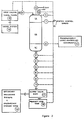
- Sensors that measure flow rate (2), column pressure (3), temperature (4), pH (5), conductivity (6), solution level in the head space (7), and metal concentration at the end of the loading section (8) and in the eluate (9) are monitored with a process control computer (10).
- the computer can be an IBM PC (or compatible) with analog and digital IO capability or a Standard Programmable Logic Controller such as an Opto 22, Mystic 100 or 200.
- the computer operates the valves and pumps to direct the flow of input solutions and the column output eluate solutions based on the inputs from the sensors in accordance with preprogrammed software.
- the sensors (8) and (9) may be, but are not limited to optical sensors, conductivity sensors, oxidation-reduction potential sensors, pH sensors, x-ray fluorescence analyzers, or infrared detector.
- the sensors (8) and (9) each comprises an opacity detector as shown schematically in figure 5 consisting of a light source (101) and a photocell (102) mounted in a tube (103) through which a sample of the fluid in the column at (8) or (9) passes at the end of the loading section (1B) and the output of the column (1C).
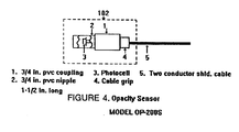
- the light source (101) consists of one or more light emitting diodes ( Figure 3) and the photocell (102) consists of a photodiode ( Figure 4) whose resistance varies according to the intensity of light passing from the light source through a sample of the fluid in the column.
- the photodiode is connected in a suitable circuit for producing an electric signal responsive to changes in the resistance of the photodiode, thus a measure of the opacity of the sample of fluid.
- a suitable circuit is shown in Figure 6, wherein the photodiode PC1 is connected in a balanced bridge circuit for producing an output suitable for controlling the computer.
- the light source is chosen to produce a colored light matching that of the metal ion to be detected. For example, a green light will enhance the sensitivity and detection of chromium ions at point (8).
- loading section (1B) and finish-section (1C) are preferably contained in the same chamber or column, it is contemplated that in certain installations these two sections may be located in separate chambers suitably linked by a pipe or tubing to carry the fluids from one to the other.
- the sensor (8) may be located in the connecting pipe or tubing.
- an 18'' (45.7 cm) diameter column as described by the second embodiment, as represented by Figure 2 is set up and directed by the computer, 40 gallons (152 liters) of 5 M hydrochloric acid is pumped to the top of the column to regenerate the resin bed.
- 155 gallons (589 liters) of 5 M hydrochloric acid previously conditioned to oxidize ferrous ions to ferric ions and filtered with a 1.0 micron filter to remove particulates, contaminated with 0.90g/L chromium, 8.5g/L iron, 2.4g/L copper, 9.6g/L zinc and 0.19g/L cadmium is loaded onto the column.
- the present invention represents a novel way to separate heavy metal ions found in toxic waste solutions especially hydrochloric acid generated in the electroplating industry, the waste water treatment industry or any solution with a concentration of complexing ions contaminated with heavy metals such as in rare earth element separation.
- the process is applied after first adsorbing the toxic metals as anionic complexes on an ion exchange resin thereby cleaning the solution for reuse.
- the invention then separates the metals from each other through an elution process that involves gradually lowering the complexing ion concentration by the addition of water in the solution surrounding the resin causing the individual metal complexes to break down and wash out of the ion exchange column in concentrated high purity solutions of metal salts.
- flow velocity of the solution past the ion exchange media has been described as being about 1.7 gpm/ft 2 (1.16 lps/m 2 )
- flow velocities of 0.5 to 5 gpm/ft 2 (0.34 to 3.4 lps/m 2 ) may be employed under certain conditions if desired.
- Slower flow rates increase separation and peak concentrations at cost of volume treated per unit time; faster flow rates increase volume treated but decrease separation and peak concentrations. This is particularly true if the temperature of the dilution solution (deionized water) is raised to 50°C.
- the temperature of the dilution system has an effect on separation quality and temperatures of the order of from 5°C to 80°C may usefully be employed.
- Any strong basic anion exchange resin may be used; however macroporous types such as Dow-M41 allow faster diffusion (higher kinetics) rates and therefore permit faster flow velocities. Resins with even higher porosities such as Rohm and Haas IRA-938 allow still higher flow velocities or provide better separation at similar flow velocities. Additionally, shorter sharpening section lengths may be utilized with higher kinetic resins.
- complexating solutions includes, but is not limited to, a metal plating solution, a cation exchange stripping solution, a solvent extraction stripping solution, a mineral or process leach solution, a circuit board manufacturing solution or other industrial process solution.
- complexating solutions also includes hydrochloric acid, hydrofluoric acid, hydroiodic acid, hydrobromic acid, or any other solution that forms one or more anionic transition metal complexes; and in which the metal contaminants are iron, zinc, cadmium, chromium, copper, nickel, tin, lead, silver, gold, mercury and any other metal that forms an anionic metal complex in the solution.
Landscapes
- Chemical & Material Sciences (AREA)
- Organic Chemistry (AREA)
- Chemical Kinetics & Catalysis (AREA)
- Engineering & Computer Science (AREA)
- Analytical Chemistry (AREA)
- Geology (AREA)
- Manufacturing & Machinery (AREA)
- Life Sciences & Earth Sciences (AREA)
- Materials Engineering (AREA)
- Mechanical Engineering (AREA)
- Metallurgy (AREA)
- Geochemistry & Mineralogy (AREA)
- General Life Sciences & Earth Sciences (AREA)
- Environmental & Geological Engineering (AREA)
- Treatment Of Water By Ion Exchange (AREA)
- Treatment Of Liquids With Adsorbents In General (AREA)
- Manufacture And Refinement Of Metals (AREA)
- Radar Systems Or Details Thereof (AREA)
Abstract
Description
- The present invention relates to the separation of metal ion contaminants from a variety of sources, such as, for example, spent stripper and activator plating solutions which are adsorbed on an anion exchange resin in the form of their anionic complexes and to the recovery, separation and purification of the metals by chromatographic elution.
- Waste HC1 acid solutions (usually 2-5 M) containing toxic metals such as chromium, lead, copper, cadium, etc. are classified as toxic waste. These solutions can come from a number of sources including the electroplating industry, the manufacture of printed circuit boards, the regeneration of cation exchange resins used in cleaning waste waters (including acidic mine drainage water), etc. The most common treatment practice for these toxic solutions in use is neutralization and precipitation which produces insoluble metal hydroxides; this method is costly because the neutralizing agent, usually sodium hydroxide, is relatively expensive. These solutions must then be replaced with new acid at additional expense. Another disadvantage is that the precipitated slurry consists of a mixture of metal hydroxides that has to be disposed of in designated toxic landfills. The disposal costs have been and will continue to rise due to tightening restrictions from the "Land Ban Act." Further, this practice does not stop the generators future liability should problems develop in the disposal facility.
- In J. P. Faris, "Adsorption of the Elements from Hydrofluoric Acid by Anion Exchange," Anal. Chem., 32, pp. 520-522 (1960); S. F. Marsh et al., "Anion Exchange of 58 Elements in Hydrobromic acid and in Hydroiodic Acid.," Report LA-7084, August 1978 by Los Alamos Scientific Laboratory; and K. A. Kraus, et al., Proc. Intern. Conf. Peaceful Uses Atomic Energy, Geneva, 7, 113 (1956), there are described various methods for the removal of anionic metal complexes from many different solutions by adsorption on an anion exchange resin as well as techniques for the analytical separation of some of these metal species. Industrial techniques currently used to remove these anionic metal complexes from the resin do not separate them, thereby resulting in a solution still classified as toxic waste.
- The present invention generally refers to a process for the removal of anionic metal complexes from complexating solutions (i.e., HCl, HF, NaCN, etc.) In which these solutions are contacted with an anion exchange resin to absorb said metal complexes thereon, which comprises selectively removing the metals therefrom by chromatographic elution, whereby the complexing ion concentration is gradually reduced causing the individual metal complexes to break: down as determined by their respective dissociation constants and thus come off of the anion exchange resin in reverse order of the dissociation constants of the individual anionic complexes, effectively separating one from the other.
- In particular, in accordance with one aspect the present invention provides a process for removing metal ions from a solution containing said metal ions as complexes having respective dissociation constants that differ from one another and then separating said metal ions from one another, which process comprises the steps of:
- (a) providing a chromatographic column of anion exchange resin capable of adsorbing said metal complexes, said column including a loading section comprising an upstream portion of said resin and a sharpening section comprising a downstream portion of said resin;
- (b) passing said solution containing said metal complexes through said column to cause said metal complexes to be adsorbed by said upstream portion of said resin, and thereby be removed from said solution, said downstream portion of said resin being left unloaded by adsorbed metal complexes;
- (c) thereafter passing a compatible non-reactive diluent through said chromatographic column in a controlled manner so that the concentration of the complexing agent in the solution contacting the resin is established and maintained above the dissociation point of all the metal complexes present except for at least one of said complexes having a dissociation point above the others for a period sufficient to allow said complex with said higher dissociation point to dissociate and the resulting metal ions from the dissociation of said complex to diffuse out of the resin into said contacting solution, and for the resulting contacting solution containing said metal ions to pass from said loading section of said resin and through said sharpening section of said resin whereby metal ions from other metal complexes that have been prematurely carried out of said loading section of said resin are readsorbed by said resin in sharpening section, thereby sharpening the purity of the metal ion solution prior to leaving the chromatographic column; and
- (d) continuing to pass said diluent through said chromatographic column to reduce the concentration of said complexing agent contacting the resin to establish and maintain said concentration at a level above the dissociation point of all but at least one of the remaining ones of said metal complexes for a period sufficient to allow the second such complex with said higher dissociation point to dissociate and the resulting metal ions from the dissociation of said complex to diffuse out of the resin into said contacting solution, and for the resulting contacting solution containing said metal ions to pass from said loading section of said resin into and through the sharpening section of said resin, whereby metal ions from other metal complexes that have prematurely carried out of said loading section of said resin are readsorbed by resin in said sharpening section, thereby sharpening the purity of the metal ion solution prior to leaving the chromatographic column.
-
- According to a further aspect of the present invention, there is provided apparatus for the chromatographic separation of a plurality of metal ions present as metal ion complexes in a complexing acid solution, said apparatus comprising a chromatographic column having an input at one end for receiving a fluid to be processed therein, an output at the opposite end thereof for withdrawing fluid therefrom, a first processing chamber intermediate the input and output ends suitable for containing a first bed of anion exchange resin in the dominant flow path of a fluid passing from the input toward the output of said column, a second processing chamber intermediate the first processing chamber and the output end of said column suitable for containing a second bed of ion exchange resin in said dominant flow path, input flow control means for selectively controlling the flow of first and second fluids introduced into the input end of said column, a source of said complexing solution coupled to said first fluid input control means, a source of water coupled to said second fluid input control means, output flow control means for selectively controlling the flow of fluid out of the output of said column, and a sensor for observing a sample of the fluid in said first chamber at the downstream end of said first bed of ion exchange resin, said sensor being responsive to the arrival of fluid introduced into the first bed for processing therein.
- Examples of metal contaminants are iron, zinc, cadium, copper and others as shown in the above referenced materials which form anionic complexes. Some embodiments and preferred embodiments are those in which: the finishing column ordinarily being greater than 4 inches (10.2cms) in length, about 30 inches (76.2cms) being the preferred, the flow velocity of the eluting solution is between about 0.5 gallons per minute per square foot of column cross sectional area (0.5 gpm/ft2)-0.34 litres per second per square metre of column cross sectional area (0.34 LPS/m2) and 5 gpm/ft2 (3.4 LPS/m2), the preferred flow velocity is about 1.7 gpm/ft2(1.16 lps/m2)at 20°C; the temperature of the eluting solution is between about 0°C to 80°C; the anion-exchange resin is a macroporous strong basic type I or II anion resin for higher flow velocities and a gel type strong basic resin for very slow flow velocities; and the complexating solution is added to the top of a chromatographic column which contains a loading section and a sharpening section approximately 30 inches (76.2 cms) long adjoined to the bottom of the loading section; both sections containing an anion exchange resin, and eluted with deionized water at a flow velocity between 0.5 and 5 gpm/ft2 (0.34 and 3.4 lps/m2) and at a temperature between about 0° and 80°C whereby the contaminating metals are successively separated. Any overlap between two successive waves of pure solution in one cycle is returned to the top of the column at the start of the elution phase of the next cycle. This allows for a more gradual decrease in complexing anions (this recycle solution contains more complexing anions than deionized water) during the initial stages of the chromatographic elution while simultaneously increasing the overall yield of separated metals to 100%.
- The present invention is based upon the discovery that it is possible to separate the metals loaded on the resins that are usually found in spent hydrochloric acid plating solutions as their chloro complexes, such metals being iron, zinc and cadmium, into eluates rich in an individual metal. The eluted fractions can be sold to the chemical industry either as solutions containing the individual metal ions, as precipitates of individual metal hydroxides or as the electrolytically recovered metal itself.
- The present invention is applicable not only to spent plating solutions as hereinbefore described, but may also be applied with equal facility to other areas besides the metal finishing industry as well as other complexing systems.
- Thus, for example, in the treatment of industrial waste water and acid mine drainage waters, ion exchange processes are used to extract the metal ions from the water. The resin is then regenerated with hydrochloric acid which becomes contaminated with iron, zinc, copper, cadmium and other toxic metals that are present in the waste water. This acid can be treated with the present process and in the same manner as other waste hydrochloric acid.
- Other applications include but are not limited to: the treatment of waste solutions from the printed circuit board industry and processing of leachates in the mining industry.
- Another application of the present invention is in the separation of rare earth elements. Current technology loads these elements on an anion exchange resin as their chloro complexes and then elutes them by passing different solutions through the columns that contain different quantities of chloride ions. Using the chromatographic process of this invention, only one instead of multiple elution solutions are needed and the total amount of elution solution is substantially reduced. Additionally, the time required for elution is greatly reduced and, accordingly, operating costs are significantly lower. Recovering separated metal ions from any process that allows transition metal ions or rare earth metal ions to be loaded on an anion exchange resin as chloro complexes can be improved by the presently described process and integrally necessary apparatus.
-
- Figure 1 shows the specialized ion exchange column for use in carrying out the process of the present invention.
- Figure 2 shows a second embodiment of the apparatus necessary for carrying out the process of the present invention. Figures 3 - 6 show various components of the sensor system.
-
- At the outset, it should be noted that the metals that are usually found in spent hydrochloric acid stripping solutions, for example, as their chloro complexes are ([Mn+ Clx]y-), where Mn+ is Fe3+, Zn2+ and Cd2+.
- The formation constants of the metal chloro complexes as well as the equilibrium constants for the distribution of these complexes between the aqueous phase and the resin phase, govern the separation of these metal complexes on the anion exchange resin. The chloride ion concentration in the aqueous phase and hence, the molarity of the hydrochloric acid in the aqueous phase has a profound influence on the separability of these chloro complexes.
- The formation constants of the chloro complexes decrease in the following sequence: Cd2+ > Zn2+ > Fe3+. On the basis of the equilibria involved, it is expected that the Cd2+ complexes will be strongly retained on the resin whereas the Fe3+ and Zn2+ will be less strongly retained. Separation of these metals is accomplished by varying the [Cl-] in the solution surrounding the resin. As the [Cl-] drops Fe3+ complexes break down and the Fe3+ comes off the resin while the Cd2+ and Zn2+ complexes remain. The Zn2+ complexes break down as the [Cl-] is dropped further. Finally, the Cd2+ complexes break down when the [Cl-] has been lowered almost to zero. The solution coming off the column is separated into fractions containing only one metal ion species.
- The [Cl-] in the solution around the resin is reduced by the addition of deionized water at the top of the column. As this water passes the first resin it picks up excess Cl- ions from the resin. The water also picks up metal ions from complexes that are broken down due to the drop in [Cl-]. As the solution continues through the column the [Cl-] builds up, rapidly reaching a level that can put the Cd2+ chloro complexes back on the resin. The [Cl-] continues to build up in this first volume of eluate until all of the the metal chloro complexes have been readsorbed onto the resin with any excess metal complexes readsorbed in the finishing section. When the first volume of solution exits the column, it is free of metals and has an HCl concentration of between 4 and 5 moles/liter. The next volume of water travels further through the column before the metals are readsorbed. As the process continues bands of metals form and travel slowly down the column with Fe3+ first, then Zn2+ and Cd2+ last. The first effluent from the column is uncontaminated HCl. This changes to a solution of pure FeCl3 when sufficient [Cl-] is removed from the ion exchange resin. The FeCl3 is followed by a solution of pure ZnCl2 and finally a solution of pure CdCl2.
- The nature of the process requires the flow velocity of the solution past the ion exchange media to be slow enough for the [Cl-] to be uniform in the media allowing only one species of metal chloro complex to break down at a time, and slow enough for the metal ions to diffuse out of the resin into the solution. If the velocity is too high, some of the Fe3+ ions will still be diffusing out of the resin when the Zn2+ complexes are breaking down. A velocity of 1.7 gpm/ft2 (1.16 lps/m2) is sufficiently low to allow these processes to take place at 15°C to 25°C with a standard macroporous resin. Gel type resins require much longer diffusion times and therefore much slower flow velocities. Special high kinetic resins such as Rohm and Haas IRA-938 have shorter diffusion times and therefore higher flow velocities can be utilized.
- The formation and decomposition of the chloro complexes are equilibrium reactions, they break down and reform continuously with the concentrations of each species reaching an equilibrium level which is a function of the equilibrium constants. Consequently, if the column is loaded all the way to the bottom some of the complexes will break down and wash out before they can be reformed and readsorbed on the resin. To prevent this bleedout of metals, the bottom section of resin is left unloaded. This novel technique provides for high purity in the individual metal chloride effluent solutions. The length of this wave sharpening section is a function of the purity required and the flow velocity in the column. Preferably, it should be 30 inches (76.2 cm) for the flow velocity necessary for this process but as will be pointed out later other lengths for the finishing section may be employed.
- Separation quality is determined by the yield of each metal in the 99% purity fraction calculated as:
- [Mi+n]zone
- = average concentration of species within the 99% purity fraction
- zone
- = volume of 99% purity fraction
- [Mi+n]mix
- = average concentration of species within the mixed fraction
- Vmix
- = volume of mixed fraction
- Separation quality drops as the flow velocity is increased and it increases with increasing the length of the sharpening section.
- The temperature of the deionized water used in the elution has an effect on the separation quality. Higher temperatures increase the diffusion rate thereby increasing the separation quality at a fixed flow velocity and a fixed sharpening section length. Example III hereinafter demonstrates that the separation quality can be maintained at a high level even with a high flow velocity (2.5 gpm/ft2 - 1.7 lps/m2) when the temperature of the elution water is raised to 110°F (43.3°C).
-
- 1. One embodiment of the apparatus is shown in Figure 1. The column is loaded with 75 liters of a macroporous strongly basic anion exchange resin such as Dow-M41 or Rohm and Haas Amberlite IRA-938 as supplied in the chloride form. Sixty liters of this resin constitutes the loading section of the column (5B) and 15 liters constitutes the sharpening section (5C). The resin is washed with water supplied from the deionized system (18) through line (19) valve (20) pump (3) valves (4) and (21) and preconditioned with 25 liters of 18% HCl from tank (12) in the same fashion. The water rinse is returned through valves (7) and (22) line (23) to the deionized water system (18). The acid is returned through valves (7) and (24) line (25) to tank (12). Effluent flow is switched from water to acid lines based on sensor (10).
- 2. The spent pregnant acid is pretreated to remove particles greater than 10 microns (0.01mm) and organic compounds such as grease, oil or wetting agents. Organic removal may be accomplished with activated carbon filters or through a solvent extraction/recovery operation or through any other suitable means. Next, the spent acid is treated with H2O2 to convert the ferrous ions to the ferric state and concentrated to 18% by the addition of HCl gas or by evaporation and subsequent addition of 32% HCl.
- 3. The concentration of metals in the spent acid is
determined and the volume of solution that will load only the
top 2 meters of the resin bed is calculated as shown:
- 4. Immediately following the spent acid, deionized water from (18) is pumped through line (19) valve (20) pump (3) valves (4) and (21) to the top of the column (5). The flow rate remains the same. The effluent is monitored by sensor (10) for Fe3+ so that when it contains more than 100 ppm iron the flow is switched from the clean acid tank (12) to the FeCl3 tank through valves (11), (13) and line (13A). The volume of FeCl3 solution on any run is dependent on the proportion of Fe in the spent acid relative to the other metals.
- 5. The FeCl3 solution is monitored by sensor (10) for Zn. When the Zn in the solution is above 50 ppm the flow is switched to a mixed metal tank through valve (14) to line (14A). At this point the concentration of Fe has typically dropped from a peak of between 10 and 25 g/l to less than 300 ppm. The flow is switched to the ZnCl2 tank (not shown) through valve (15) and line (15A) when the Fe concentration has dropped to 50 ppm. The volume of mixed metal solution is small and it contains only small quantities of Fe and Zn. This solution is concentrated with cation exchange column (26) which is eluted with acid from tank (12). The eluate is returned to tank (1) for reprocessing.
- 6. The ZnCl2 solution contains between 5 and 15 g/l Zn2+. The effluent is now monitored by sensor (10) for Cd. When the [Cd] exceeds 50 ppm the flow is switched from line (15A) to the mixed metal tank again through valve (16) and line (16A) until the [Zn] has dropped to less than 50 ppm. Then effluent flow is switched to line (17). The volume of this mixed metal solution is also small as are the quantity of metals. This solution is also concentrated in cation exchange column (26) in the same manner as before (step 5).
- 7. The CdCl2 is monitored by sensor (10) for [Cd] and the elution is complete when the [Cd] drops below 10 ppm. Depending on the relative concentration in the spent acid the [Cd] in the majority of the CdCl2 solution is between 150 and 1500 ppm. The pH of this solution is between 3 and 4. This solution is passed through cation exchange column (29) removing the Cd, then through valve (30) back to the deionized water system (18). Cation exchange column (29) is eluted with HCl acid from tank (12) and the eluate CdCl2 with a concentration of approximately 10 gm/l flows through valve (30) to storage tank (31).
- 8. Deionized water (75 liters) from system (18) is pumped by pump (3) upflow through valves (4), (22), (24) and (7) to the bottom of column (5) to restratify the resin bed for better flow dynamics. Any gas such as air is vented through relief valve (6) at this time.
- 9. The resin is still in the Cl- form but the solution in and around the resin beads has to be reconditioned to high [Cl-] prior to the start of the next cycle. This is accomplished by pumping 25 L of clean 18% HCl from tank (12) downflow through the column at 8 Lpm exiting through valves (7) and (24) line (25) to tank (12) when sensor (10) indicates acid instead of water. The high flow rate packs the resin to prevent channels from forming. The system is now ready for the next cycle.
-
- The invention will be described in greater detail in conjunction with the following specific examples. It is to be understood however that while the present invention is described in detail in the specific examples as dealing with spent plating solutions containing high concentrations of heavy metal ions in hydrochloric acid solutions generated by the metal finishing industry, the invention is not limited to such solutions but as hereinbefore described may be applied with equal facility to other areas where it is desired to remove metal contaminants such as in the treatment of waste water or industrial process water and in the separation of rare earth metals where ion exchange processes are used to separate various metals as their chloro complexes. Nor is the invention limited to chloro complexes. Any anionic metal complexing system can be utilized by the invention according to the distribution coefficients as outlined in the referenced materials and according to their respective dissociation constants.
- It is also to be understood that while standard tap water can be used in accordance with the present invention to lower the concentration of the complexing agent thereby eluting the metals removed from the complexing solution, deionized water is used for this purpose in a preferred embodiment thereof, thereby providing a cleaner eluted fraction for use by the chemical industry. It will be appreciated that in some cases the use of distilled water or water purified by reverse osmosis will provide an eluted fraction that meets most technical grade chemical standards. This is really a matter to be determined by the use to be made of the eluted fraction and will be dictated by the current market conditions or specific customer needs.
- For testing purposes a 1.5'' (3.8cm) diameter column is set up (identical to the one described previously), and loaded with 4 liters of Dow M41 resin, 3 liters in the loading section and 1 liter in the sharpening section (30 inches). Five liters of spent activator bath from a local plating shop is pretreated and loaded on the column. Deionized water (20°C) is run through the column at 80 ml/minute (1.7 gpm/ft2). Samples are taken of each volume fraction of effluent and then analyzed for metal content. 1.0 liter of clean 4 M HCl constitutes the first fraction. 1.75 liters of FeCl3 containing 22.8 gm or 95.2% of the iron loaded and 93 mg of zinc constitutes the second fraction. A volume of 0.25 liters of mixed metal ion solution containing 0.48 gm Zn and 0.42 gm Fe constitutes the third fraction. 12.5 liters of ZnCl2 solution containing 71.3 gm Zn or 99.1% of the Zn loaded and 0.64 gm of Fe plus 0.3 gm Cd for a purity of 98.7% constitutes the fourth fraction. 0.5 liters of a mixed metal ion metal solution containing 100 mg Zn and 200 mg Cd constitutes the fifth fraction. 30.5 liters of CdCl2 solution containing 13.4 gm Cd and 120 mg Zn constitutes the sixth and last fraction. These results are shown in Table I below.
Fraction Volume (ml) Fe (gms) Zn (gms) Cd (gms) 1 1,900 0.10 0.01 - Recycle 2 1,750 22.8 0.09 - Fe p=99.6% Fraction y=95.2% 3 250 0.42 0.48 - Recycle 4 12,500 0.64 71.30 0.30 Zn p=98.7% Fraction y=98.7% 5 500 - 0.10 0.20 Recycle 6 30,500 - 0.12 13.40 Cd p=98.8% Fraction y=96.4% Where:
p = purity
y = yield - This example shows how the length of the sharpening section affects the separation quality. The apparatus, flow velocity and temperature used in Example I are kept the same. Eight liters of the same spend acid is passed through the column thereby loading 60% more metal ions onto the resin reducing the sharpening section (visual determination) to approximately three inches.
- The quantities of metal in each fraction are shown in Table II below. The yields in the 98% purity fraction dropped 2-4% from Example I which reflects the increased overlap of the zones. However, the yields remain above 93%.
Fraction Volume (ml) Fe (gms) Zn (gms) Cd (gms) 1 550 0.04 - - Recycle 2 3,250 37.10 0.60 - Fe p=98.4% Fraction y=93.6% 3 500 2.20 3.00 - Recycle 4 11,250 0.28 94.50 0.65 Zn p=98.9% Fraction y=94.8% 5 1,000 - 1.30 .42 Recycle y=94.8% 6 30,000 - 0.33 14.90 Cd p=97.8% Fraction y=93.3% Where:
p = purity
y = yield - This example shows how hot water elution allows increased flow velocity without a drop in separation quality. The same apparatus is used but the flow velocity is increased to 120 ml/min. Five liters of the same spent acid is passed through the column loading the resin with metal ions. The deionized water is heated to 50°C and then run through the column. The results are shown in Table III below. The yields for this example are higher than Example I.
Fraction Volume (ml) Fe (gms) Zn (gms) Cd (gms) 1 2,000 0.07 - - Recycle 2 2,000 24.60 0.04 - Fe p=99.8% Fraction y=96.7% 3 500 0.65 0.75 - Recycle 4 12,750 0.11 59.70 0.04 Zn p=99.7% Fraction y=97.6% 5 1,100 - 0.54 0.25 Recycle 6 25,000 - 0.15 11.10 Cd p=98.6% Fraction y=97.5% Where:
p = purity
y = yield - A second embodiment of the apparatus is shown in Figure 2. An 18 inch (45.7cm) diameter column, 13.5 feet (4.1m) in length, is loaded with 500 liters of a macroporous strongly basic anion exchange resin such as Dow M-41 or Rhom and Haas IRA-938 as supplied in the chloride form. 375 liters of this resin constitutes the loading section of the column (1B) and 125 liters constitutes the sharpening section (1C) leaving approximately three feet of head space (1A). Sensors that measure flow rate (2), column pressure (3), temperature (4), pH (5), conductivity (6), solution level in the head space (7), and metal concentration at the end of the loading section (8) and in the eluate (9) are monitored with a process control computer (10). The computer can be an IBM PC (or compatible) with analog and digital IO capability or a Standard Programmable Logic Controller such as an
Opto 22,Mystic 100 or 200. The computer operates the valves and pumps to direct the flow of input solutions and the column output eluate solutions based on the inputs from the sensors in accordance with preprogrammed software. - The sensors (8) and (9) may be, but are not limited to optical sensors, conductivity sensors, oxidation-reduction potential sensors, pH sensors, x-ray fluorescence analyzers, or infrared detector.
- Preferably, the sensors (8) and (9) each comprises an opacity detector as shown schematically in figure 5 consisting of a light source (101) and a photocell (102) mounted in a tube (103) through which a sample of the fluid in the column at (8) or (9) passes at the end of the loading section (1B) and the output of the column (1C). In a preferred embodiment, the light source (101) consists of one or more light emitting diodes (Figure 3) and the photocell (102) consists of a photodiode (Figure 4) whose resistance varies according to the intensity of light passing from the light source through a sample of the fluid in the column.
- The photodiode is connected in a suitable circuit for producing an electric signal responsive to changes in the resistance of the photodiode, thus a measure of the opacity of the sample of fluid. A suitable circuit is shown in Figure 6, wherein the photodiode PC1 is connected in a balanced bridge circuit for producing an output suitable for controlling the computer. Advantageously, the light source is chosen to produce a colored light matching that of the metal ion to be detected. For example, a green light will enhance the sensitivity and detection of chromium ions at point (8).
- 1. The spent pregnant acid is pretreated to remove particles greater than 1.0 microns (0.001mm) and organic compounds such as grease, oil or wetting agents. Organic removal may be accomplished with activated carbon filters or through a solvent extraction/recovery operation or through any other suitable means. Next, the spent acid is treated with H2O2 or O2 or Cl2 to convert the ferrous ions to the ferric state and concentrated to 18% by the addition of HCl gas or by evaporation and subsequent addition of 32% HCl.
- 2. Directed by the computer, 40 gallons (152 liters) of 5.0 M hydrochloric acid is pumped to the top of the column to regenerate the resin bed. Output is directed to the low zinc or the cadmium subsystem as determined by the presence of cadmium in the spent acid previously loaded.
- 3. The computer directs the spent acid to the top of the column after allowing the level of clean regenerant acid in the column to fall just above the top of the resin in order to minimize mixing of the two dissimilar solutions utilizing level detector (7). Additional spent acid is added to the column and again allowed to fall to just above the top of the resin as is done in all similar instances throughout the run. The flow of spent acid is continued until the sensor at the bottom of the loading section detects the presence of metal ions which indicates that the resin is now loaded to the desired amount.
- 4. The computer regulates flow control valve (11) thereby maintaining the flow velocity through the resin at the desired value. The computer also regulates the pressure in the top of the column by either addition of pressurized air, valve (12), or venting of excess pressure, pressure relief valve (13), thereby assisting the flow control by providing positive constant pressure on the solution of the column.
- 5. Next the computer directs a twenty-five gallon (95 litres) metal-free 5.0 hydrochloric acid plug to be pumped to the column to elute any unretained cation, i.e. Cr+3.
- 6. With the completion of the clean acid plug, 100 gallons of a Mixed-metal/Recycle solution (acquired during the mix phases of the previous run) at a pH of 2.0 is added to the column to increase the effective metal recovery yield to 100%; an on-line flow meter (14) signals the 100 gallons addition.
- 7. The computer next directs deionized water to the column through input valve bank (15) from water system (16).
- 8. A conductivity sensor (6) indicates the presence of the eluting hydrochloric acid, causing the computer to direct the output flow through the output valve bank (17) to the product acid recovery tank (18).
- 9. A sensor (9) (an XRF, colorimeter, on-line titrator, or other applicable device) indicates the presence of iron or iron/copper mix in the eluate, directs the computer to switch the output valve bank (17) to direct the flow to the appropriate secondary processing system (19).
- 10. Input from the sensor indicating a decrease in metal concentration of a particular fraction signals the computer to direct the eluate through the appropriate valve to the Mixed-metal/Recycle Tank (19) until the sensor no longer detects the presence of the metal.
- 11. In the absence of metals being detected by the sensor (9), the computer directs the eluate into the zinc or zinc/lead recovery tank (19) until the conductivity sensor (6) reaches a certain level.
- 12. Directed by input from the conductivity sensor (6) the computer switches the appropriate valve to direct the eluate to the low level zinc subsystem (19).
- 13. Should cadmium be present in the original impregnated acid, the eluate sensor (9) signals the arrival of cadmium in the eluate and directs the computer to switch the appropriate valve to the cadmium subsystem (19) and maintains this configuration until cadmium is no longer being detected.
- 14. When all of the above criteria have been met, the computer instructs the system to shut itself down.
-
- Although the loading section (1B) and finish-section (1C) are preferably contained in the same chamber or column, it is contemplated that in certain installations these two sections may be located in separate chambers suitably linked by a pipe or tubing to carry the fluids from one to the other. In this case, the sensor (8) may be located in the connecting pipe or tubing.
- For testing purposes, an 18'' (45.7 cm) diameter column as described by the second embodiment, as represented by Figure 2 is set up and directed by the computer, 40 gallons (152 liters) of 5 M hydrochloric acid is pumped to the top of the column to regenerate the resin bed. Next, 155 gallons (589 liters) of 5 M hydrochloric acid, previously conditioned to oxidize ferrous ions to ferric ions and filtered with a 1.0 micron filter to remove particulates, contaminated with 0.90g/L chromium, 8.5g/L iron, 2.4g/L copper, 9.6g/L zinc and 0.19g/L cadmium is loaded onto the column. Following this, 25 gallons of metal-free hydrochloric acid is added to the column to elute any unretained species, i.e. chromium. Next 100 gallons (380 liters) of a Mixed metal/Recycle solution from a previous run at a pH of 2.0 is added to the column to increase the effective metal recovery yield to 100%. Finally, deionized water at 60°C is added to the column continuously until the cycle is complete. Samples are taken of each volume fraction of effluent and then analyzed for metal content. 145 gallons (551 liters) of 5.0 M hydrochloric acid with 96 ppm chromium constitutes the first fraction. 50 gallon (190 liters) of FeCl3 and CuCl2 with 25.03g/L or 95.0% iron and 7.14g/L or 96.0% copper with 2 ppm zinc constitutes the second fraction. 25 gallons of Mixed-metal/Recycle solution with 2.6g/L iron, 0.595g/L zinc constitutes the third fraction. 521 (1980 liters) gallons of ZnCl2 of 2.78g/L or 97.3% of the zinc loaded onto the column with 7 ppm iron and 5 ppm copper constitutes a fourth fraction. 75 gallons of a second Mixed-metal/Recycle solution with 0.139g/L zinc and 9 ppm cadmium constitutes the fifth fraction. And 70 gallon (266 liters) of CdCl2 with 0.413g/L or 97.6% of the cadmium loaded and 4 ppm zinc constitutes the sixth and final fraction. These results are shown in Table IV below.
- This example demonstrates that the invention can be performed on the larger scale represented by the second embodiment and that the use of a process control computer enhances the overall effectiveness of the invention. Also in some cases, it is necessary to elute two metals with similar properties simultaneously which in no way limits the invention's applicability.
Product Acid w/ Chromium Iron (III) chloride Zinc chloride Cadmium chloride 160 Gallons (608 liters) received: 5M Hydrochloric acid with: 35 Gallons (133 liters): FeCl3 with: 510 Gallons (1938 liters): ZnCl2 with: 35 Gallons (133 liters): CdCl2 with: [Cr] = < 1 ppm [Cr] = <1 ppm [Cr] = <1 ppm [Cr] = 97.8 ppm [Fe] = 46.1 g/L [Fe] = 15 ppm [Fe] = <1 ppm [Fe] = < 1 ppm [Zn] = 2 ppm [Zn] = 2.95g/L [Zn] = 4 ppm [Zn] = < 1 ppm [Cd] = < 1 ppm [Cd] = 3 ppm [Cd] = 30g/L [Cd] = < 1 ppm recovery = 95.0% recovery = 96.1% recovery = 98.5% HCl recovery = 94.1% purity = 99.98% purity = 99.91% purity = 99.97% HCl purity = 99.9% Cr recovery = 100.0% - The present invention represents a novel way to separate heavy metal ions found in toxic waste solutions especially hydrochloric acid generated in the electroplating industry, the waste water treatment industry or any solution with a concentration of complexing ions contaminated with heavy metals such as in rare earth element separation. The process is applied after first adsorbing the toxic metals as anionic complexes on an ion exchange resin thereby cleaning the solution for reuse. The invention then separates the metals from each other through an elution process that involves gradually lowering the complexing ion concentration by the addition of water in the solution surrounding the resin causing the individual metal complexes to break down and wash out of the ion exchange column in concentrated high purity solutions of metal salts.
- The separation of these metals in this process requires a specially designed and operated ion exchange column requiring:
- A) a flow velocity sufficiently low to allow the diffusion of the ions into and out of the resin beads to reach completion before each incremental column of solution passes on to the next incremental volume of resin; and B) a sharpening section of ion exchange resin at the bottom of the column that was not loaded with any metal complexes in the initial cycle of operation thereby preventing premature bleeding of the more stable metal complexes into the fractions of clean solution and the less stable metal complexes that are the first to wash out of the column.
-
- While the present invention has been particularly described in connection with a length of the sharpening section of the column of about 30 inches (76.2 cm), it is to be understood that different lengths may be employed if desired. Thus sharpening sections of from about 4 inches (10.2 cm) or greater in length can be used to effect excellent separation of the metals.
- Moreover, while the flow velocity of the solution past the ion exchange media has been described as being about 1.7 gpm/ft2(1.16 lps/m2), flow velocities of 0.5 to 5 gpm/ft2 (0.34 to 3.4 lps/m2) may be employed under certain conditions if desired. Slower flow rates increase separation and peak concentrations at cost of volume treated per unit time; faster flow rates increase volume treated but decrease separation and peak concentrations. This is particularly true if the temperature of the dilution solution (deionized water) is raised to 50°C. The temperature of the dilution system has an effect on separation quality and temperatures of the order of from 5°C to 80°C may usefully be employed.
- Any strong basic anion exchange resin may be used; however macroporous types such as Dow-M41 allow faster diffusion (higher kinetics) rates and therefore permit faster flow velocities. Resins with even higher porosities such as Rohm and Haas IRA-938 allow still higher flow velocities or provide better separation at similar flow velocities. Additionally, shorter sharpening section lengths may be utilized with higher kinetic resins.
- The presence of complexing ions in the elution solution will slow down the process and increase the volume of regenerant required. However, this may be required in some separations where two metal species have similar distribution coefficients such as cupric and ferric ions. Also, the introduction into the top of the column of overlap from a previous cycle containing complexing ions and metal contaminants at the beginning of the elution phase enhances the separation of the metals while increasing the overall effectiveness of the process as the small percentage of waste (overlap) is recycled without further processing.
- Metals that have been separated successfully by the described process to date are:
- In HCl,
- Fe Zn Cd
- Cr Fe Zn Cd where Cr remains in acid
- Ni Fe Zn Cd where Ni remains in acid
- Ni Cu Zn Cd where Ni remains in acid
- Cr Cu Zn Cd where Cr remains in acid
- Ni Cu Pb Sn where Ni remains in acid
- Fe Cu Sb Zn
-
- It should be noted that the number of permutations and combinations given 40 plus metals in one complexating solution alone is astronomical. However, in every case so far attempted in the laboratory the outcome is easily predicted from the distribution coefficients given in the incorporated references. With these coefficients it is possible to predict the performance of the invention for many possible combinations of metal in these referenced complexing systems.
- It is to be understood that the expression "complexating solutions" as used throughout the present specification and claims includes, but is not limited to, a metal plating solution, a cation exchange stripping solution, a solvent extraction stripping solution, a mineral or process leach solution, a circuit board manufacturing solution or other industrial process solution. The term "complexating solutions" also includes hydrochloric acid, hydrofluoric acid, hydroiodic acid, hydrobromic acid, or any other solution that forms one or more anionic transition metal complexes; and in which the metal contaminants are iron, zinc, cadmium, chromium, copper, nickel, tin, lead, silver, gold, mercury and any other metal that forms an anionic metal complex in the solution.
Claims (36)
- A process for removing metal ions from a solution containing said metal ions as complexes with a complexing agent, said metal complexes having respective dissociation constants that differ from one another and then separating said metal ions from one another, which process comprises the steps of:(a) providing a chromatographic column of anion exchange resin capable of adsorbing said metal complexes, said column including a loading section comprising an upstream portion of said resin and a sharpening section comprising a downstream portion of said resin;(b) passing said solution containing said metal complexes through said column to cause said metal complexes to be adsorbed by said upstream portion of said resin, and thereby be removed from said solution, said downstream portion of said resin being left unloaded by adsorbed metal complexes;(c) thereafter passing a compatible non-reactive diluent through said chromatographic column in a controlled manner so that the concentration of the complexing agent in the solution contacting the resin is established and maintained above the dissociation point of all the metal complexes present except for at least one of said complexes having a dissociation point above the others for a period sufficient to allow said complex with said higher dissociation point to dissociate and the resulting metal ions from the dissociation of said complex to diffuse out of the resin into said contacting solution, and for the resulting contacting solution containing said metal ions to pass from said loading section of said resin and through said sharpening section of said resin whereby metal ions from other metal complexes that have been prematurely carried out of said loading section of said resin are readsorbed by said resin in sharpening section, thereby sharpening the purity of the metal ion solution prior to leaving the chromatographic column; and(d) continuing to pass said diluent through said chromatographic column to reduce the concentration of said complexing agent contacting the resin to establish and maintain said concentration at a level above the dissociation point of all but at least one of the remaining ones of said metal complexes for a period sufficient to allow the second such complex with said higher dissociation point to dissociate and the resulting metal ions from the dissociation of said complex to diffuse out of the resin into said contacting solution, and for the resulting contacting solution containing said metal ions to pass from said loading section of said resin into and through the sharpening section of said resin, whereby metal ions from other metal complexes that have prematurely carried out of said loading section of said resin are readsorbed by resin in said sharpening section, thereby sharpening the purity of the metal ion solution prior to leaving the chromatographic column.
- A process according to Claim 1, which further involves repeating step (d) until all of the metal complexes have been dissociated and removed from the chromatographic column.
- A process according to Claim 1 or Claim 2, wherein said loading section and said sharpening section of said chromatographic column are located in separate chambers linked for fluid communication by a pipe or tubing.
- A process according to any preceding claim, wherein said at least one of the complexes having a dissociation point above the others is the metal complex having the highest dissociation point.
- A process according to any preceding claim, wherein the solution for treatment for removal of metal ions is a waste hydrochloric acid solution in which said metal ions being present as chloro-complexes having different dissociation constants, and wherein the process of selectively removing respective ones of the metal ions from the anion exchange resin comprises introducing said diluent into said column to control the chloride ion concentration of the solution to a level that is effective selectively to dissociate in turn said metal chloro-complexes according to their respective dissociation constants.
- A process according to Claim 5, wherein said metal ions comprise iron and zinc.
- A process according to any one of Claims 1-4, wherein the solution for treatment for removal of metal ions is a contaminated hydrochloric acid, hydrofluoric acid, hydroiodic acid or hydrobromic acid solution in which the metal contaminants for removal are zinc, iron, cadmium, chromium, copper, nickel, tin, lead, silver, gold and/or mercury.
- A process according to Claim 5 or Claim 7, wherein the solution for treatment for removal of metal ions is a hydrochloric acid pickling solution from a zinc galvanizing plant.
- A process according to any one of Claims 5-8, wherein the flow velocity of the diluent is from 0.5 gallons per minute per square foot (gpm/ft2) to 5 gpm/ft2(0.34 to 3.4 lps/m2)
- A process according to Claim 9 wherein said flow velocity is from 1 to 2 gpm/ft2 (0.68 to 1.36 lps/m2) at 20°C.
- A process according to any preceding claim, wherein the temperature of the diluent is from 0° to 80°C.
- A process according to any preceding claim, wherein said non-reactive diluent is water.
- A process according to Claim 12, wherein the diluent is water purified by deionization or reverse osmosis.
- A process according to any preceding claim, wherein said diluent is introduced into the top of said chromatographic column.
- A process according to any preceding claim, wherein the anion exchange resin is a strong base quaternary ammonium-DVB type standard resin.
- A process according to Claim 15, wherein said anion exchange resin is a macroporous (high kinetics) Type I or Type II resin.
- A process according to any preceding claim, wherein the length of said sharpening section of said chromatographic column is about 76.2 cms (about 30 inches).
- A process according to any preceding claim, wherein contacting solution eluted from the chromatographic column and containing more than one metal due to overlap is returned to the column directly after the next loading cycle, thereby beginning the next elution step with a smaller complexing ion concentration gradient in order to increase the separation quality.
- A process according to any preceding claim, wherein a volume of clean solution of the complexing agent is added to the chromatographic column directly after the loading cycle to help wash out any metals which were in the solution to be treated but which do not form complexes with the complexing agent and which therefore do not load onto the resin, thereby increasing the separation between these metals and the first metals eluted.
- A process according to any preceding claim, further includes sensing and controlling the level of the feed solution in a head space in the chromatographic column above the anion exchange resin for the purpose of minimizing mixing of different solutions during transition between a loading cycle and an elution cycle or between any two cycles where the input solution to said column is changed.
- Apparatus for the chromatographic separation of a plurality of metal ions present as metal ion complexes in a complexing acid solution, said apparatus comprising a chromatographic column having an input at one end for receiving a fluid to be processed therein, an output at the opposite end thereof for withdrawing fluid therefrom, a first processing chamber intermediate the input and output ends suitable for containing a first bed of anion exchange resin in the dominant flow path of a fluid passing from the input toward the output of said column, a second processing chamber intermediate the first processing chamber and the output end of said column suitable for containing a second bed of ion exchange resin in said dominant flow path, input flow control means for selectively controlling the flow of first and second fluids introduced into the input end of said column, a source of said complexing solution coupled to said first fluid input control means, a source of water coupled to said second fluid input control means, output flow control means for selectively controlling the flow of fluid out of the output of said column, and a sensor for observing a sample of the fluid in said first chamber at the downstream end of said first bed of ion exchange resin, said sensor being responsive to the arrival of fluid introduced into the first bed for processing therein.
- Apparatus according to Claim 21, wherein said first and second processing chambers are adjacent sections of said chromatographic column and the first and second beds of ion exchange resin are located in said column substantially contiguous with one another.
- Apparatus according to Claim 21 or Claim 22, wherein said sensor provides an output signal coupled to the input control means for switching from the first to the second fluid input of the column when the arrival of said first fluid is detected at the downstream end of said first bed of anion exchange resin.
- Apparatus according to any one of Claims 21-23, wherein said sensor comprises an opacity detector including a light-emitting diode and a photodiode and wherein light passing from the light-emitting diode to the photodiode passes through the observed sample of the fluid at the downstream end of said first bed of ion exchange resin.
- Apparatus according to any one of Claims 21-24, further comprising a plurality of storage containers and means including said output flow control means for selectively directing the flow of fluid from said column to a selected storage container in response to a signal derived from said sensor.
- Apparatus according to any one of Claims 21-25, wherein the first bed of the chromatographic column comprises a loading section greater than 76.2 cms (30 inches) in length, said second bed comprises a finishing section greater than 25.4 cms (10 inches) in length and means are provided for controlling the flow velocity of said solution through the column between 0.5 and 5.0 gallons per minute per square foot of column cross-sectional area (0.34 to 3.4 lps/m2)
- Apparatus according to Claim 26, comprising apparatus for determining when the loading section has been fully loaded so that the loading cycle can be terminated prior to loading of the finishing section, said apparatus comprising a sensor or detector for detecting the presence of a selected metal ion present in the complexing solution.
- Apparatus according to Claim 26, comprising apparatus for sensing and controlling the level of the feed solution in a head space in the chromatographic column above the anion exchange resin for the purpose of minimizing mixing of different solutions during transition between the loading cycle and the elution cycle or between any two cycles where the input solution to said column is changed.
- Apparatus according to Claim 26, including means for controlling the pressure in a head space above the anion exchange resin whereby pressurized air is added to or vented from the chromatographic column to maintain the necessary column pressure to achieve the desired flow velocity of solution through said column.
- Apparatus according to Claim 26, for detecting the individual metal fractions and purities as eluted from said column and areas for diverting said different metal-containing eluate solutions to appropriate storage tanks, said apparatus comprising one or more detectors capable of differentiating between the metal species present in the original solution.
- A chromatographic elution apparatus for use in the separation of metal ions on an anion exchange resin comprising a source of water, a source of metal bearing complexing solution, a column containing a loading section and a finishing section adjoined on the bottom of the loading section, said column having an anion exchange resin for the purpose of adsorbing anionic metal complexes thereon, means for delivering metal bearing complexing solution to the top of said column to flow downwardly through the column to load the loading section, means for delivering water to the top of said column to flow downwardly through said resin and so as to elute with water and successively remove and separate the metals from each other as metal salts in solution with the finishing section being arranged to enhance the separation of the metal ions through extension of the natural chromatographic effects of the process, and means to control the flow velocity of said solutions as they exit said column.
- An apparatus according to claim 31 further comprising means for determining when the loading section has been fully loaded and terminating delivery of complexing solution prior to loading of the finishing section.
- An apparatus according to claim 31 or 32 that includes a sensor or detector suitable for detecting the presence of a particular metal ion present in the effluent solution.
- An apparatus according to claim 31 or 32 including means for detecting the individual metal fractions and purities as eluted from said column and means for diverting said different metal-containing eluate solutions to appropriate storage tanks, said means comprising one or more detectors capable of differentiating between the metal species present in the original solution.
- An apparatus according to claim 31 or 32 wherein said loading section is greater than 30 inches (76.2 cm) in length and said finishing section is greater than 10 inches (25.4 cm) in length.
- An apparatus according to claim 31 or 32 wherein said means to control the flow velocity of said solutions as they exit said column controls the flow velocity between 0.5 and 5.0 gallons per minute per square foot of column cross-sectional area (0.34 to 3.4 LPS/m2).
Applications Claiming Priority (2)
| Application Number | Priority Date | Filing Date | Title |
|---|---|---|---|
| US07/909,009 US5246591A (en) | 1990-07-13 | 1992-07-06 | Separation of metal ions on an anion exchange resin by chromatographic elution |
| US909009 | 2001-07-18 |
Publications (2)
| Publication Number | Publication Date |
|---|---|
| EP0578347A1 EP0578347A1 (en) | 1994-01-12 |
| EP0578347B1 true EP0578347B1 (en) | 1999-12-08 |
Family
ID=25426504
Family Applications (1)
| Application Number | Title | Priority Date | Filing Date |
|---|---|---|---|
| EP93301564A Expired - Lifetime EP0578347B1 (en) | 1992-07-06 | 1993-03-01 | Separation of metal ions on an anion exchange resin by chromatographic elution |
Country Status (13)
| Country | Link |
|---|---|
| US (2) | US5246591A (en) |
| EP (1) | EP0578347B1 (en) |
| JP (1) | JPH06108169A (en) |
| KR (1) | KR940005306A (en) |
| AT (1) | ATE187423T1 (en) |
| AU (1) | AU661168B2 (en) |
| CA (1) | CA2099815A1 (en) |
| DE (1) | DE69327198T2 (en) |
| DK (1) | DK0578347T3 (en) |
| ES (1) | ES2141131T3 (en) |
| GR (1) | GR3032747T3 (en) |
| MX (1) | MX9304034A (en) |
| PT (1) | PT578347E (en) |
Families Citing this family (20)
| Publication number | Priority date | Publication date | Assignee | Title |
|---|---|---|---|---|
| NL9500065A (en) * | 1995-01-12 | 1996-08-01 | Bammens Groep B V | Method for selectively removing zinc from acidic waste streams. |
| US6689485B2 (en) | 1997-01-17 | 2004-02-10 | The Penn State Research Foundation | Powerful reductant for decontamination of groundwater and surface streams |
| KR100311946B1 (en) * | 1998-07-01 | 2001-12-28 | 김서곤 | Mat for isolating frequence of water vein |
| FI110668B (en) * | 2000-06-20 | 2003-03-14 | Aboatech Ab Oy | Use of probiotics for primary prophylaxis of atopic diseases |
| CA2528171C (en) * | 2003-07-16 | 2011-12-06 | Amalgamated Research Llc | Method for the recovery of acids from hydrometallurgy process solutions |
| US7387720B2 (en) * | 2004-04-30 | 2008-06-17 | Metara, Inc. | Electrolytic method and apparatus for trace metal analysis |
| DE102004061255B4 (en) * | 2004-12-20 | 2007-10-31 | Atotech Deutschland Gmbh | Process for the continuous operation of acidic or alkaline zinc or zinc alloy baths and apparatus for carrying it out |
| JP4723629B2 (en) * | 2008-11-13 | 2011-07-13 | Jx日鉱日石金属株式会社 | Silver recovery method using anion exchange resin |
| GB201007354D0 (en) * | 2010-04-30 | 2010-06-16 | Algeta Asa | Method |
| US20120076832A1 (en) * | 2010-08-04 | 2012-03-29 | University Of North Texas | Synthesis and use of therapeutic metal ion containing polymeric particles |
| KR102340262B1 (en) * | 2014-09-05 | 2021-12-15 | 에코랍 유에스에이 인코퍼레이티드 | Addition of aluminum reagents to oxoanion-containing water streams |
| US10071923B2 (en) | 2014-09-05 | 2018-09-11 | Ecolab Usa Inc. | Addition of aluminum reagents to oxoanion-containing water streams |
| US9389209B2 (en) | 2014-09-05 | 2016-07-12 | Ecolab Usa Inc. | Oxoanion concentration determination using aluminum reagents |
| US11940430B2 (en) * | 2015-05-22 | 2024-03-26 | Shimadzu Corporation | Suppressor system, and method for determining life of ion exchange resin column |
| KR101780248B1 (en) | 2017-03-31 | 2017-09-20 | 한국지질자원연구원 | Apparatus for Lithium ions adsorption and desorption process on land and Recovery method using thereof |
| JP6877228B2 (en) * | 2017-04-24 | 2021-05-26 | 三菱ケミカルアクア・ソリューションズ株式会社 | Soluble substance separator, control device and soluble substance separation method |
| JP7249317B2 (en) * | 2020-08-07 | 2023-03-30 | 株式会社 イージーエス | METHOD FOR SEPARATING METAL AND METAL SEPARATING DEVICE |
| CN116262946A (en) * | 2021-12-15 | 2023-06-16 | 中国科学院青岛生物能源与过程研究所 | A method for separating and extracting valuable metals from the acidic leaching solution of waste battery ternary materials using a chromatographic separation system |
| CN115522050A (en) * | 2022-10-24 | 2022-12-27 | 德庆兴邦稀土新材料有限公司 | Method for removing impurities in ion exchange resin rare earth feed liquid |
| CN117250253B (en) * | 2023-11-14 | 2024-09-10 | 中国计量科学研究院 | A method for determining iron, copper and zinc in biological samples |
Family Cites Families (21)
| Publication number | Priority date | Publication date | Assignee | Title |
|---|---|---|---|---|
| US2636044A (en) * | 1951-06-22 | 1953-04-21 | Eugene H Huffman | Rare earth separation by anion exchange |
| US2694681A (en) * | 1952-03-07 | 1954-11-16 | Univ Idaho Res Foundation Inc | Recycling the complexing agent in the separation of ions by ion exchange |
| US2753258A (en) * | 1953-01-19 | 1956-07-03 | Nat Res Dev | Method of recovering gold from cyanide solutions |
| US2873170A (en) * | 1954-06-17 | 1959-02-10 | Earl K Hyde | Anion exchange method for separation of metal values |
| US2797190A (en) * | 1954-09-20 | 1957-06-25 | California Research Corp | Adsorption separation process |
| US2967148A (en) * | 1955-12-02 | 1961-01-03 | Blaw Knox Co | Selective adsorption process and apparatus |
| US2965441A (en) * | 1956-11-29 | 1960-12-20 | Du Pont | Ion exchange for the recovery of chemicals |
| US2962351A (en) * | 1957-05-23 | 1960-11-29 | Peter C Stevenson | Treatment for improving the operation of strong base anion exchange resins |
| US3003866A (en) * | 1958-06-18 | 1961-10-10 | Dow Chemical Co | Selective elution of copper, nickel, and cobalt from aminocarboxylic acid chelate exchange resins |
| US3414510A (en) * | 1968-02-29 | 1968-12-03 | Nalco Chemical Co | Method for selectively removing chromates |
| DE2526247A1 (en) * | 1975-06-12 | 1976-12-30 | Oxy Effluent Control Ltd | Recovering acid and metals from spent pickling soln. - using anionic exchange resin to remove metal forming anionic complex |
| US3965441A (en) * | 1975-06-20 | 1976-06-22 | Trw Inc. | Parallel resonant circuit with feedback means for increasing Q |
| DE2602440A1 (en) * | 1976-01-23 | 1977-07-28 | Steinmueller Gmbh L & C | Removing zinc from hydrochloric acid-contg. solns. - by forming zinc chloro complex on anion exchanger and then converting to zinc chloride |
| US4335000A (en) * | 1977-09-13 | 1982-06-15 | Pennwalt Corporation | Chromate ion removal from aqueous solutions |
| NL8201654A (en) * | 1982-04-21 | 1983-11-16 | Tno | POLYETHERURETHANE GRANES WITH ABSORBING ACTION, METHOD FOR PREPARING THESE POLYETHERURETHANE GRANULES, AND METHOD FOR EXTRACTING OR SEPARATING METALS FROM LIQUIDS USING THESE GRANULES. |
| CS245861B1 (en) * | 1984-06-01 | 1986-10-16 | Zdenek Matejka | Method of heavy metals separation from aminocarboxyl complexing substances |
| US4770788A (en) * | 1985-04-25 | 1988-09-13 | Kollmorgen Technologies Corp. | Process for removing metal complexes from waste solutions |
| US4765909A (en) * | 1987-04-23 | 1988-08-23 | Gte Laboratories Incorporated | Ion exchange method for separation of scandium and thorium |
| DE3924100A1 (en) * | 1989-07-20 | 1991-01-24 | Didier Werke Ag | METHOD FOR REMOVING HEAVY METALS FROM SEWAGE |
| DE4010265C2 (en) * | 1990-03-30 | 1997-07-24 | Karlsruhe Forschzent | Process for the separate extraction of complex images and uncomplexed metal ions from waste water |
| DE4116000A1 (en) * | 1991-05-16 | 1992-11-19 | Degussa | Sepg. gold and silver complexes from aq. systems of cyanide or halogen - by absorption on strongly basic anion exchanger based on polymeric crosslinked organo:siloxane ammonium cpds. |
-
1992
- 1992-07-06 US US07/909,009 patent/US5246591A/en not_active Expired - Fee Related
-
1993
- 1993-03-01 PT PT93301564T patent/PT578347E/en unknown
- 1993-03-01 DK DK93301564T patent/DK0578347T3/en active
- 1993-03-01 DE DE69327198T patent/DE69327198T2/en not_active Expired - Fee Related
- 1993-03-01 EP EP93301564A patent/EP0578347B1/en not_active Expired - Lifetime
- 1993-03-01 ES ES93301564T patent/ES2141131T3/en not_active Expired - Lifetime
- 1993-03-01 AT AT93301564T patent/ATE187423T1/en not_active IP Right Cessation
- 1993-06-30 JP JP5187487A patent/JPH06108169A/en active Pending
- 1993-07-05 CA CA002099815A patent/CA2099815A1/en not_active Abandoned
- 1993-07-05 MX MX9304034A patent/MX9304034A/en not_active IP Right Cessation
- 1993-07-05 KR KR1019930012721A patent/KR940005306A/en not_active Withdrawn
- 1993-07-06 AU AU41777/93A patent/AU661168B2/en not_active Ceased
- 1993-08-31 US US08/094,559 patent/US5372717A/en not_active Expired - Fee Related
-
2000
- 2000-02-23 GR GR20000400447T patent/GR3032747T3/en not_active IP Right Cessation
Also Published As
| Publication number | Publication date |
|---|---|
| US5372717A (en) | 1994-12-13 |
| GR3032747T3 (en) | 2000-06-30 |
| CA2099815A1 (en) | 1994-01-07 |
| EP0578347A1 (en) | 1994-01-12 |
| JPH06108169A (en) | 1994-04-19 |
| DE69327198T2 (en) | 2000-04-06 |
| PT578347E (en) | 2000-05-31 |
| AU661168B2 (en) | 1995-07-13 |
| ATE187423T1 (en) | 1999-12-15 |
| DE69327198D1 (en) | 2000-01-13 |
| US5246591A (en) | 1993-09-21 |
| ES2141131T3 (en) | 2000-03-16 |
| DK0578347T3 (en) | 2000-03-27 |
| AU4177793A (en) | 1994-01-13 |
| KR940005306A (en) | 1994-03-21 |
| MX9304034A (en) | 1994-05-31 |
Similar Documents
| Publication | Publication Date | Title |
|---|---|---|
| US5372717A (en) | Separation of metal ions on an anion exchange resin by chromatographic elution | |
| EP0417194B1 (en) | Method and apparatus for purifying hydrogen fluoride | |
| Hathaway et al. | Removing arsenic from drinking water | |
| AU2011349335B2 (en) | Rhenium recovery | |
| Gaikwad et al. | Ion exchange system design for removal of heavy metals from acid mine drainage wastewater | |
| CA2528171C (en) | Method for the recovery of acids from hydrometallurgy process solutions | |
| CA2051016A1 (en) | Nickel recovery process | |
| Cardellicchio et al. | Determination of cadmium and lead at μg/1 levels in aqueous matrices by chelation ion chromatography | |
| US4863612A (en) | Apparatus and method for recovering materials from process baths | |
| CA2525274A1 (en) | Method and apparatus for desorbing material | |
| Virolainen et al. | Ion exchange purification of a silver nitrate electrolyte | |
| Short et al. | The GM‐IX process: A pilot study for recovering zinc cyanides | |
| US4756833A (en) | Metal-containing waste water treatment and metal recovery process | |
| ZA200509091B (en) | Method and apparatus for desorbing material | |
| AU2003242501B2 (en) | Method and apparatus for desorbing material | |
| Sheedy | Case studies in applying recoflo ion-exchange technology | |
| Van Tonder, GJ*, Cilliers, PJ*, Meyer, EHO**, Vegter, NM***, Klue, R.****, Izatt, SR***** & Bruening | Cobalt and nickel removed from Zincor impure electrolyte by Molecular Recognition Technology (MRT)-pilot plant demonstration | |
| DE4204870A1 (en) | Disposing of soil or water loaded with arsenic - by passing soln. through anion exchange resin, eluting resin to recover arsenic, sepg. arsenic from eluate and regenerating resin | |
| Valiente et al. | Separation of copper and zinc from waste acidic mine effluents of Río Tinto area | |
| Mindler | Application in hydrometallurgy | |
| Tan | Acid-salt separation by selective adsorption with ion-exchange resins | |
| SU1696536A1 (en) | Method of processing mineral acid solutions containing antimony and metal cations | |
| Jafar | A Study of Zinc Separation from an Alkaline Leach Liquor Using Fixed and Moving Bed Ion Exchange Systems | |
| Millman et al. | Some successful applications of electrodialysis | |
| Roberts | Developments in continuous ion exchange equipment for AEC applications |
Legal Events
| Date | Code | Title | Description |
|---|---|---|---|
| PUAI | Public reference made under article 153(3) epc to a published international application that has entered the european phase |
Free format text: ORIGINAL CODE: 0009012 |
|
| AK | Designated contracting states |
Kind code of ref document: A1 Designated state(s): AT BE CH DE DK ES FR GB GR IE IT LI LU MC NL PT SE |
|
| 17P | Request for examination filed |
Effective date: 19940620 |
|
| 17Q | First examination report despatched |
Effective date: 19950630 |
|
| RAP1 | Party data changed (applicant data changed or rights of an application transferred) |
Owner name: MARS TECHNOLOGIES INCORPORATED |
|
| GRAG | Despatch of communication of intention to grant |
Free format text: ORIGINAL CODE: EPIDOS AGRA |
|
| GRAG | Despatch of communication of intention to grant |
Free format text: ORIGINAL CODE: EPIDOS AGRA |
|
| GRAH | Despatch of communication of intention to grant a patent |
Free format text: ORIGINAL CODE: EPIDOS IGRA |
|
| GRAH | Despatch of communication of intention to grant a patent |
Free format text: ORIGINAL CODE: EPIDOS IGRA |
|
| GRAA | (expected) grant |
Free format text: ORIGINAL CODE: 0009210 |
|
| AK | Designated contracting states |
Kind code of ref document: B1 Designated state(s): AT BE CH DE DK ES FR GB GR IE IT LI LU MC NL PT SE |
|
| REF | Corresponds to: |
Ref document number: 187423 Country of ref document: AT Date of ref document: 19991215 Kind code of ref document: T |
|
| ITF | It: translation for a ep patent filed | ||
| REG | Reference to a national code |
Ref country code: CH Ref legal event code: EP |
|
| REG | Reference to a national code |
Ref country code: CH Ref legal event code: NV Representative=s name: KIRKER & CIE SA |
|
| REF | Corresponds to: |
Ref document number: 69327198 Country of ref document: DE Date of ref document: 20000113 |
|
| ET | Fr: translation filed | ||
| REG | Reference to a national code |
Ref country code: IE Ref legal event code: FG4D |
|
| REG | Reference to a national code |
Ref country code: ES Ref legal event code: FG2A Ref document number: 2141131 Country of ref document: ES Kind code of ref document: T3 |
|
| REG | Reference to a national code |
Ref country code: DK Ref legal event code: T3 |
|
| REG | Reference to a national code |
Ref country code: PT Ref legal event code: SC4A Free format text: AVAILABILITY OF NATIONAL TRANSLATION Effective date: 20000225 |
|
| PLBE | No opposition filed within time limit |
Free format text: ORIGINAL CODE: 0009261 |
|
| STAA | Information on the status of an ep patent application or granted ep patent |
Free format text: STATUS: NO OPPOSITION FILED WITHIN TIME LIMIT |
|
| 26N | No opposition filed | ||
| PGFP | Annual fee paid to national office [announced via postgrant information from national office to epo] |
Ref country code: GB Payment date: 20010228 Year of fee payment: 9 |
|
| PGFP | Annual fee paid to national office [announced via postgrant information from national office to epo] |
Ref country code: PT Payment date: 20010301 Year of fee payment: 9 |
|
| PGFP | Annual fee paid to national office [announced via postgrant information from national office to epo] |
Ref country code: SE Payment date: 20010306 Year of fee payment: 9 Ref country code: DE Payment date: 20010306 Year of fee payment: 9 |
|
| PGFP | Annual fee paid to national office [announced via postgrant information from national office to epo] |
Ref country code: LU Payment date: 20010309 Year of fee payment: 9 |
|
| PGFP | Annual fee paid to national office [announced via postgrant information from national office to epo] |
Ref country code: FR Payment date: 20010313 Year of fee payment: 9 Ref country code: DK Payment date: 20010313 Year of fee payment: 9 Ref country code: AT Payment date: 20010313 Year of fee payment: 9 |
|
| PGFP | Annual fee paid to national office [announced via postgrant information from national office to epo] |
Ref country code: CH Payment date: 20010315 Year of fee payment: 9 |
|
| PGFP | Annual fee paid to national office [announced via postgrant information from national office to epo] |
Ref country code: ES Payment date: 20010323 Year of fee payment: 9 |
|
| PGFP | Annual fee paid to national office [announced via postgrant information from national office to epo] |
Ref country code: IE Payment date: 20010328 Year of fee payment: 9 |
|
| PGFP | Annual fee paid to national office [announced via postgrant information from national office to epo] |
Ref country code: GR Payment date: 20010329 Year of fee payment: 9 |
|
| PGFP | Annual fee paid to national office [announced via postgrant information from national office to epo] |
Ref country code: NL Payment date: 20010330 Year of fee payment: 9 |
|
| PGFP | Annual fee paid to national office [announced via postgrant information from national office to epo] |
Ref country code: MC Payment date: 20010402 Year of fee payment: 9 |
|
| PGFP | Annual fee paid to national office [announced via postgrant information from national office to epo] |
Ref country code: BE Payment date: 20010516 Year of fee payment: 9 |
|
| REG | Reference to a national code |
Ref country code: GB Ref legal event code: IF02 |
|
| PG25 | Lapsed in a contracting state [announced via postgrant information from national office to epo] |
Ref country code: MC Free format text: LAPSE BECAUSE OF NON-PAYMENT OF DUE FEES Effective date: 20020301 Ref country code: LU Free format text: LAPSE BECAUSE OF NON-PAYMENT OF DUE FEES Effective date: 20020301 Ref country code: IE Free format text: LAPSE BECAUSE OF NON-PAYMENT OF DUE FEES Effective date: 20020301 Ref country code: GB Free format text: LAPSE BECAUSE OF NON-PAYMENT OF DUE FEES Effective date: 20020301 Ref country code: AT Free format text: LAPSE BECAUSE OF NON-PAYMENT OF DUE FEES Effective date: 20020301 |
|
| PG25 | Lapsed in a contracting state [announced via postgrant information from national office to epo] |
Ref country code: SE Free format text: LAPSE BECAUSE OF NON-PAYMENT OF DUE FEES Effective date: 20020302 Ref country code: ES Free format text: LAPSE BECAUSE OF NON-PAYMENT OF DUE FEES Effective date: 20020302 |
|
| PG25 | Lapsed in a contracting state [announced via postgrant information from national office to epo] |
Ref country code: LI Free format text: LAPSE BECAUSE OF NON-PAYMENT OF DUE FEES Effective date: 20020331 Ref country code: CH Free format text: LAPSE BECAUSE OF NON-PAYMENT OF DUE FEES Effective date: 20020331 Ref country code: BE Free format text: LAPSE BECAUSE OF NON-PAYMENT OF DUE FEES Effective date: 20020331 |
|
| PG25 | Lapsed in a contracting state [announced via postgrant information from national office to epo] |
Ref country code: DK Free format text: LAPSE BECAUSE OF NON-PAYMENT OF DUE FEES Effective date: 20020402 |
|
| BERE | Be: lapsed |
Owner name: *MARS TECHNOLOGIES INC. Effective date: 20020331 |
|
| PG25 | Lapsed in a contracting state [announced via postgrant information from national office to epo] |
Ref country code: PT Free format text: LAPSE BECAUSE OF NON-PAYMENT OF DUE FEES Effective date: 20020930 |
|
| PG25 | Lapsed in a contracting state [announced via postgrant information from national office to epo] |
Ref country code: NL Free format text: LAPSE BECAUSE OF NON-PAYMENT OF DUE FEES Effective date: 20021001 Ref country code: DE Free format text: LAPSE BECAUSE OF NON-PAYMENT OF DUE FEES Effective date: 20021001 |
|
| PG25 | Lapsed in a contracting state [announced via postgrant information from national office to epo] |
Ref country code: GR Free format text: LAPSE BECAUSE OF NON-PAYMENT OF DUE FEES Effective date: 20021007 |
|
| EUG | Se: european patent has lapsed |
Ref document number: 93301564.6 |
|
| GBPC | Gb: european patent ceased through non-payment of renewal fee |
Effective date: 20020301 |
|
| REG | Reference to a national code |
Ref country code: CH Ref legal event code: PL |
|
| REG | Reference to a national code |
Ref country code: DK Ref legal event code: EBP |
|
| PG25 | Lapsed in a contracting state [announced via postgrant information from national office to epo] |
Ref country code: FR Free format text: LAPSE BECAUSE OF NON-PAYMENT OF DUE FEES Effective date: 20021129 |
|
| NLV4 | Nl: lapsed or anulled due to non-payment of the annual fee |
Effective date: 20021001 |
|
| REG | Reference to a national code |
Ref country code: PT Ref legal event code: MM4A Free format text: LAPSE DUE TO NON-PAYMENT OF FEES Effective date: 20020930 |
|
| REG | Reference to a national code |
Ref country code: IE Ref legal event code: MM4A |
|
| REG | Reference to a national code |
Ref country code: FR Ref legal event code: ST |
|
| REG | Reference to a national code |
Ref country code: ES Ref legal event code: FD2A Effective date: 20030410 |
|
| PG25 | Lapsed in a contracting state [announced via postgrant information from national office to epo] |
Ref country code: IT Free format text: LAPSE BECAUSE OF NON-PAYMENT OF DUE FEES;WARNING: LAPSES OF ITALIAN PATENTS WITH EFFECTIVE DATE BEFORE 2007 MAY HAVE OCCURRED AT ANY TIME BEFORE 2007. THE CORRECT EFFECTIVE DATE MAY BE DIFFERENT FROM THE ONE RECORDED. Effective date: 20050301 |