EP0578104A2 - Road vehicle tire manufacturing method - Google Patents
Road vehicle tire manufacturing method Download PDFInfo
- Publication number
- EP0578104A2 EP0578104A2 EP93110347A EP93110347A EP0578104A2 EP 0578104 A2 EP0578104 A2 EP 0578104A2 EP 93110347 A EP93110347 A EP 93110347A EP 93110347 A EP93110347 A EP 93110347A EP 0578104 A2 EP0578104 A2 EP 0578104A2
- Authority
- EP
- European Patent Office
- Prior art keywords
- tire
- mold
- station
- cooling
- fact
- Prior art date
- Legal status (The legal status is an assumption and is not a legal conclusion. Google has not performed a legal analysis and makes no representation as to the accuracy of the status listed.)
- Granted
Links
Images

Classifications
-
- B—PERFORMING OPERATIONS; TRANSPORTING
- B29—WORKING OF PLASTICS; WORKING OF SUBSTANCES IN A PLASTIC STATE IN GENERAL
- B29D—PRODUCING PARTICULAR ARTICLES FROM PLASTICS OR FROM SUBSTANCES IN A PLASTIC STATE
- B29D30/00—Producing pneumatic or solid tyres or parts thereof
- B29D30/06—Pneumatic tyres or parts thereof (e.g. produced by casting, moulding, compression moulding, injection moulding, centrifugal casting)
- B29D30/08—Building tyres
-
- B—PERFORMING OPERATIONS; TRANSPORTING
- B29—WORKING OF PLASTICS; WORKING OF SUBSTANCES IN A PLASTIC STATE IN GENERAL
- B29D—PRODUCING PARTICULAR ARTICLES FROM PLASTICS OR FROM SUBSTANCES IN A PLASTIC STATE
- B29D30/00—Producing pneumatic or solid tyres or parts thereof
- B29D30/0005—Pretreatment of tyres or parts thereof, e.g. preheating, irradiation, precuring
-
- B—PERFORMING OPERATIONS; TRANSPORTING
- B29—WORKING OF PLASTICS; WORKING OF SUBSTANCES IN A PLASTIC STATE IN GENERAL
- B29C—SHAPING OR JOINING OF PLASTICS; SHAPING OF MATERIAL IN A PLASTIC STATE, NOT OTHERWISE PROVIDED FOR; AFTER-TREATMENT OF THE SHAPED PRODUCTS, e.g. REPAIRING
- B29C33/00—Moulds or cores; Details thereof or accessories therefor
- B29C33/02—Moulds or cores; Details thereof or accessories therefor with incorporated heating or cooling means
-
- B—PERFORMING OPERATIONS; TRANSPORTING
- B29—WORKING OF PLASTICS; WORKING OF SUBSTANCES IN A PLASTIC STATE IN GENERAL
- B29D—PRODUCING PARTICULAR ARTICLES FROM PLASTICS OR FROM SUBSTANCES IN A PLASTIC STATE
- B29D30/00—Producing pneumatic or solid tyres or parts thereof
- B29D30/06—Pneumatic tyres or parts thereof (e.g. produced by casting, moulding, compression moulding, injection moulding, centrifugal casting)
- B29D30/0601—Vulcanising tyres; Vulcanising presses for tyres
- B29D30/0662—Accessories, details or auxiliary operations
- B29D2030/0675—Controlling the vulcanization processes
- B29D2030/0677—Controlling temperature differences
-
- Y—GENERAL TAGGING OF NEW TECHNOLOGICAL DEVELOPMENTS; GENERAL TAGGING OF CROSS-SECTIONAL TECHNOLOGIES SPANNING OVER SEVERAL SECTIONS OF THE IPC; TECHNICAL SUBJECTS COVERED BY FORMER USPC CROSS-REFERENCE ART COLLECTIONS [XRACs] AND DIGESTS
- Y10—TECHNICAL SUBJECTS COVERED BY FORMER USPC
- Y10S—TECHNICAL SUBJECTS COVERED BY FORMER USPC CROSS-REFERENCE ART COLLECTIONS [XRACs] AND DIGESTS
- Y10S264/00—Plastic and nonmetallic article shaping or treating: processes
- Y10S264/46—Molding using an electrical heat
-
- Y—GENERAL TAGGING OF NEW TECHNOLOGICAL DEVELOPMENTS; GENERAL TAGGING OF CROSS-SECTIONAL TECHNOLOGIES SPANNING OVER SEVERAL SECTIONS OF THE IPC; TECHNICAL SUBJECTS COVERED BY FORMER USPC CROSS-REFERENCE ART COLLECTIONS [XRACs] AND DIGESTS
- Y10—TECHNICAL SUBJECTS COVERED BY FORMER USPC
- Y10S—TECHNICAL SUBJECTS COVERED BY FORMER USPC CROSS-REFERENCE ART COLLECTIONS [XRACs] AND DIGESTS
- Y10S264/00—Plastic and nonmetallic article shaping or treating: processes
- Y10S264/65—Processes of preheating prior to molding
-
- Y—GENERAL TAGGING OF NEW TECHNOLOGICAL DEVELOPMENTS; GENERAL TAGGING OF CROSS-SECTIONAL TECHNOLOGIES SPANNING OVER SEVERAL SECTIONS OF THE IPC; TECHNICAL SUBJECTS COVERED BY FORMER USPC CROSS-REFERENCE ART COLLECTIONS [XRACs] AND DIGESTS
- Y10—TECHNICAL SUBJECTS COVERED BY FORMER USPC
- Y10S—TECHNICAL SUBJECTS COVERED BY FORMER USPC CROSS-REFERENCE ART COLLECTIONS [XRACs] AND DIGESTS
- Y10S425/00—Plastic article or earthenware shaping or treating: apparatus
- Y10S425/039—Pre-heat
Definitions
- the present invention relates to a road vehicle tire manufacturing method.
- Italian Patent Application n. TO91A 000820 to which full reference is made herein in the interest of full disclosure, relates to a road vehicle tire manufacturing process whereby a green tire is assembled inside an annular forming mold having a toroidal inner chamber negatively reproducing the surface of the finished tire.
- the forming mold is fitted and gripped between two opposite portions of a curing unit having a curing bladder, which is inserted inside the tire and mold, and defines part of a heat exchange gas circuit.
- the curing unit is opened, the bladder removed from the tire, and the tire unloaded off the curing unit together with the forming mold inside which the tire is housed pending completion of the postinflation stage.
- a road vehicle tire manufacturing method characterized by the fact that it comprises stages consisting in successively feeding a toroidal forming mold, housing a finished green tire, through a first preheating station wherein first heating means are connected to the forming mold for preheating given portions of the green tire; through a second curing station wherein the mold is connected to a curing unit pending completion of the curing process; and through a third postinflation station wherein the tire is engaged by means for cooling given portions of the tire.
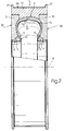
- Number 1 in Fig.2 indicates a mold for forming a tire 2, and comprising a first and second inner annular support 3 and 4 for respective bead portions 5 of tire 2.
- Annular supports 3 and 4 are defined internally by respective cylindrical surfaces 6 and 7 coaxial with axis 8, and are connected releasably to the inner edge of respective annular plates 9 and 10, the outer edges of which are connected releasably to respective axial ends of an outer annular body 11.
- annular body 11 defines a toroidal chamber 12, the inner edge of which communicates externally through an annular opening 13 defined between annular supports 3 and 4 and extending about axis 8, and which presents an inner surface 14 negatively reproducing the outer surface of finished tire 2.
- Station 15 presents a number of outer peripheral annular heating element 18 of different sizes, each consisting of two half rings 19 supported on respective arms 20 extending upwards from respective powered slides 21 running along respective slideways 22 substantially perpendicular to rail 16.
- Each arm 20 is connected to respective half ring 19 via the interposition of a known actuator 23 for moving half ring 19 parallel to rail 16.
- mold 1 of a given size i.e. for forming a given sized tire 2
- known linear actuators activate slides 21 of the two half rings 19 of heating element 18 sized to mate perfectly with the outer surface 24 of mold 1.
- the two half rings 19 are positioned by respective slides 21 on either side of mold 1 standing in station 15, and respective actuators 23 are activated for moving half rings 19 into contact with surface 24.
- Station 15 also presents a number of inner peripheral annular heating elements 25 of different sizes, each consisting of two annular heating bodies 26 and 27 located on either side of rail 16 and slightly larger in diameter than inner annular supports 3 and 4 of mold 1.
- Annular bodies 26 and 27 are all supported on respective appendixes 28 extending radially from respective coaxial shafts 29 substantially perpendicular to rail 16.
- Shafts 29 are connected to the output of and rotated by respective motors 30, each supported on a respective arm 31 extending upwards from a respective powered slide 32 running along a respective slideway 33 substantially perpendicular to rail 16.
- mold 1 of a given size i.e. for forming a given sized tire 2
- motors 30 are operated for positioning two annular bodies 26 and 27 of the right size coaxial with mold 1; and known linear actuators (not shown) activate slides 32 for moving annular bodies 26 and 27 into contact with the outer surface 34 of respective annular plates 9 and 10, substantially at the bead portions 5 of tire 2 inside mold 1.
- heating elements 18 and 25 are connected respectively to outer annular body 11 and annular plates 9 and 10, and, when activated, provide for respectively preheating tread portion 35 and bead portions 5 of tire 2, i.e. the parts having a greater thermal inertia as compared with the rest of tire 2.
- mold 1 is removed from curing unit 39 and fed to a parting station 43 where mold 1 and tire 2 are fitted through with a known tubular auxiliary support 44, which engages annular supports 3 and 4 in fluidtight manner, and provides, in known manner not shown, for feeding compressed air inside tire 2.
- mold 1 is then parted by removing annular plates 9 and 10 followed by outer annular body 11.
- Tire 2 still fitted to annular supports 3 and 4 and tubular support 44, is then fed to postinflation station 45.
- Station 45 presents a number of annular cooling elements 46 of different sizes, each consisting of two annular bodies 47 and 48 located on either side of tubular support 44 and slightly larger in diameter than inner annular supports 3 and 4 fitted to tire 2.
- Annular bodies 47 and 48 are all supported on respective appendixes 49 extending radially from respective coaxial shafts 50 connected to the output of and rotated by respective motors 51.
- Each motor 51 is supported on a respective arm 52 extending upwards from a respective powered slide 53 running along a respective slideway 54 parallel to respective shaft 50.
- motors 51 are operated for positioning two annular bodies 47 and 48 of the right size coaxial with tire 2; and known linear actuators (not shown) activate slides 53 for moving annular bodies 47 and 48 into contact with respective bead portions 5 of tire 2.
- cooling element 46 is connected to bead portions 5, and, when activated, provides for cooling bead portions 5 relatively rapidly and so preventing the heat stored during curing by the metal beads (not shown) in bead portions 5 from overcuring the sidewalls of tire 2 at the postinflation stage.
Landscapes
- Engineering & Computer Science (AREA)
- Mechanical Engineering (AREA)
- Moulds For Moulding Plastics Or The Like (AREA)
- Heating, Cooling, Or Curing Plastics Or The Like In General (AREA)
- Tyre Moulding (AREA)
Abstract
Description
- The present invention relates to a road vehicle tire manufacturing method.
- Italian Patent Application n. TO91A 000820, to which full reference is made herein in the interest of full disclosure, relates to a road vehicle tire manufacturing process whereby a green tire is assembled inside an annular forming mold having a toroidal inner chamber negatively reproducing the surface of the finished tire.
- According to the above patent, the forming mold is fitted and gripped between two opposite portions of a curing unit having a curing bladder, which is inserted inside the tire and mold, and defines part of a heat exchange gas circuit. At the end of the curing stage, the curing unit is opened, the bladder removed from the tire, and the tire unloaded off the curing unit together with the forming mold inside which the tire is housed pending completion of the postinflation stage.
- The above known process presents several drawbacks normally due to the long curing and postinflation times involved, and the difficulty encountered, during curing, in controlling the temperature of the various parts of the tire for preventing local burning and/or overcuring and/or undercuring.
- An important point to note in connection with the above is that the mass of the tire is mainly centered about the bead and tread portions, which thus require a relatively long curing time, whereas the sidewalls tend, not only to cure faster, but also to overcure or burn as a result of the heat yielded by the metal beads after curing.
- It is an object of the present invention to provide a method enabling a reduction in curing time and, consequently, in energy consumption, and which at the same time provides for improving in-curing heat distribution within the tire.
- It is a further object of the present invention to prevent local overcuring caused by excessive heat exchange, after curing, between adjacent parts of the tire.
- According to the present invention, there is provided a road vehicle tire manufacturing method, characterized by the fact that it comprises stages consisting in successively feeding a toroidal forming mold, housing a finished green tire, through a first preheating station wherein first heating means are connected to the forming mold for preheating given portions of the green tire; through a second curing station wherein the mold is connected to a curing unit pending completion of the curing process; and through a third postinflation station wherein the tire is engaged by means for cooling given portions of the tire.
- A non-limiting embodiment of the present invention will be described by way of example with reference to the accompanying drawings, in which:
- Fig.1 shows a schematic view in perspective of a preferred embodiment of the method according to the present invention;
- Fig.2 shows an axial section of a forming mold employed in the Fig.1 method.
- Number 1 in Fig.2 indicates a mold for forming a
tire 2, and comprising a first and second innerannular support 3 and 4 forrespective bead portions 5 oftire 2.Annular supports 3 and 4 are defined internally by respective cylindrical surfaces 6 and 7 coaxial with axis 8, and are connected releasably to the inner edge of respectiveannular plates 9 and 10, the outer edges of which are connected releasably to respective axial ends of an outerannular body 11. Together withannular plates 9 and 10 andannular supports 3 and 4,annular body 11 defines atoroidal chamber 12, the inner edge of which communicates externally through anannular opening 13 defined betweenannular supports 3 and 4 and extending about axis 8, and which presents aninner surface 14 negatively reproducing the outer surface of finishedtire 2. - As shown in Fig.1, once formed in known manner inside
toroidal chamber 12,green tire 2 is fed, together with forming mold 1, to apreheating station 15 into which mold 1 is rolled along a rail 16 (only part of which is shown), for which purpose, outerannular body 11 of mold 1 presents two outerannular flanges 17 forengaging rail 16. -
Station 15 presents a number of outer peripheralannular heating element 18 of different sizes, each consisting of twohalf rings 19 supported onrespective arms 20 extending upwards from respective poweredslides 21 running alongrespective slideways 22 substantially perpendicular to rail 16. Eacharm 20 is connected to respectivehalf ring 19 via the interposition of a knownactuator 23 for movinghalf ring 19 parallel torail 16. - When mold 1 of a given size, i.e. for forming a given sized
tire 2, is rolled intostation 15 alongrail 16, known linear actuators (not shown) activateslides 21 of the twohalf rings 19 ofheating element 18 sized to mate perfectly with theouter surface 24 of mold 1. The twohalf rings 19 are positioned byrespective slides 21 on either side of mold 1 standing instation 15, andrespective actuators 23 are activated for movinghalf rings 19 into contact withsurface 24. -
Station 15 also presents a number of inner peripheralannular heating elements 25 of different sizes, each consisting of twoannular heating bodies rail 16 and slightly larger in diameter than innerannular supports 3 and 4 of mold 1.Annular bodies respective appendixes 28 extending radially from respective coaxial shafts 29 substantially perpendicular to rail 16. Shafts 29 are connected to the output of and rotated byrespective motors 30, each supported on arespective arm 31 extending upwards from a respective poweredslide 32 running along arespective slideway 33 substantially perpendicular to rail 16. - When mold 1 of a given size, i.e. for forming a given sized
tire 2, is rolled intostation 15 alongrail 16,motors 30 are operated for positioning twoannular bodies slides 32 for movingannular bodies outer surface 34 of respectiveannular plates 9 and 10, substantially at thebead portions 5 oftire 2 inside mold 1. - In other words, when mold 1 is arrested in
station 15,heating elements annular body 11 andannular plates 9 and 10, and, when activated, provide for respectively preheatingtread portion 35 and beadportions 5 oftire 2, i.e. the parts having a greater thermal inertia as compared with the rest oftire 2. - Upon
tread portion 35 and beadportions 5 being preheated to the required temperature,heating elements rail 16 to curingstation 36 and arrested coaxial with the twoportions curing unit 39.Portions rail 16 and supported onrespective slides rail 16, so as to grip mold 1, the outer edge of which is enclosed, instation 36, by the two half rings of a further outer peripheralannular heating element 42 substantially identical toelements 18 already described. - Once
tire 2 is cured, which is performed relatively rapidly by virtue oftread portion 35 andbead portions 5 being preheated instation 15, mold 1 is removed from curingunit 39 and fed to aparting station 43 where mold 1 andtire 2 are fitted through with a known tubularauxiliary support 44, which engagesannular supports 3 and 4 in fluidtight manner, and provides, in known manner not shown, for feeding compressed air insidetire 2. - Still in
station 43, mold 1 is then parted by removingannular plates 9 and 10 followed by outerannular body 11. -
Tire 2, still fitted toannular supports 3 and 4 andtubular support 44, is then fed topostinflation station 45. -
Station 45 presents a number ofannular cooling elements 46 of different sizes, each consisting of twoannular bodies tubular support 44 and slightly larger in diameter than innerannular supports 3 and 4 fitted totire 2.Annular bodies respective appendixes 49 extending radially from respectivecoaxial shafts 50 connected to the output of and rotated by respective motors 51. Each motor 51 is supported on arespective arm 52 extending upwards from a respective poweredslide 53 running along arespective slideway 54 parallel torespective shaft 50. - When a
tire 2 of a given size arrives instation 45, motors 51 are operated for positioning twoannular bodies tire 2; and known linear actuators (not shown) activateslides 53 for movingannular bodies bead portions 5 oftire 2. - In other words, when
tire 2 is arrested instation 45,cooling element 46 is connected to beadportions 5, and, when activated, provides forcooling bead portions 5 relatively rapidly and so preventing the heat stored during curing by the metal beads (not shown) inbead portions 5 from overcuring the sidewalls oftire 2 at the postinflation stage.
Claims (6)
- A road vehicle tire manufacturing method, characterized by the fact that it comprises stages consisting in successively feeding a toroidal forming mold (1), housing a finished green tire (2), through a first preheating station (15) wherein first heating means (18, 25) are connected to the forming mold (1) for preheating given portions (5, 35) of the green tire (2); through a second curing station (36) wherein the mold (1) is connected to a curing unit (39) pending completion of the curing process; and through a third postinflation station (45) wherein the tire (2) is engaged by means (46) for cooling given portions (5) of the tire (2).
- A method as claimed in Claim 1, characterized by the fact that said heating means (18, 25) comprise an outer peripheral annular heating element (18) which is fitted to said forming mold (1) for preheating a tread portion (35) of said green tire (2); said outer annular heating element (18) being selected from a number of similar outer annular heating elements (18) of different sizes.
- A method as claimed in Claim 1 or 2, characterized by the fact that said heating means (18, 25) comprise a pair of inner peripheral annular heating elements (26, 27) which are fitted to said forming mold (1) for preheating respective bead portions (5) of said green tire (2); said pair of inner annular heating elements (26, 27) being selected from a number of pairs of similar inner annular heating elements (26, 27) of different sizes.
- A method as claimed in any one of the foregoing Claims, characterized by the fact that, prior to reaching said third station (45), the mold (1) is parted and the tire (2) removed from the mold (1).
- A method as claimed in Claim 4, characterized by the fact that, prior to parting the mold (1), the mold (1) and tire (2) are engaged by a tubular support (44) which provides for supporting the tire (2) when the tire (2) is removed from the mold (1) and also when the tire (2) is engaged by said cooling means (46) at said third station.
- A method as claimed in any one of the foregoing Claims, characterized by the fact that said cooling means (46) comprise a pair of inner peripheral annular cooling elements (47, 48) which are fitted to the tire (2) for cooling respective bead portions (5) of the same; said pair of inner annular cooling elements (47, 48) being selected from a number of pairs of similar inner annular cooling elements (47, 48) of different sizes.
Applications Claiming Priority (2)
| Application Number | Priority Date | Filing Date | Title |
|---|---|---|---|
| ITTO920554 | 1992-07-01 | ||
| ITTO920554A IT1259599B (en) | 1992-07-01 | 1992-07-01 | METHOD FOR THE PRODUCTION OF ROAD VEHICLE TIRES. |
Publications (3)
| Publication Number | Publication Date |
|---|---|
| EP0578104A2 true EP0578104A2 (en) | 1994-01-12 |
| EP0578104A3 EP0578104A3 (en) | 1994-03-30 |
| EP0578104B1 EP0578104B1 (en) | 1996-12-27 |
Family
ID=11410569
Family Applications (1)
| Application Number | Title | Priority Date | Filing Date |
|---|---|---|---|
| EP93110347A Expired - Lifetime EP0578104B1 (en) | 1992-07-01 | 1993-06-29 | Road vehicle tire manufacturing method |
Country Status (6)
| Country | Link |
|---|---|
| US (1) | US5384084A (en) |
| EP (1) | EP0578104B1 (en) |
| JP (1) | JP3233744B2 (en) |
| DE (1) | DE69306867T2 (en) |
| ES (1) | ES2096807T3 (en) |
| IT (1) | IT1259599B (en) |
Cited By (4)
| Publication number | Priority date | Publication date | Assignee | Title |
|---|---|---|---|---|
| EP0638409B1 (en) * | 1993-08-09 | 1998-10-07 | Sedepro | Method and apparatus for vulcanizing tyres |
| EP1215024A2 (en) * | 2000-12-12 | 2002-06-19 | Bridgestone Corporation | Method and apparatus for the manufacture of pneumatic tires |
| WO2007013113A1 (en) * | 2005-07-29 | 2007-02-01 | Pirelli Tyre S.P.A. | Method and apparatus for the vulcanisation of tyres for vehicle wheels |
| WO2007013112A1 (en) * | 2005-07-29 | 2007-02-01 | Pirelli Tyre S.P.A. | Method and apparatus for the vulcanisation of tyres for vehicle wheels |
Families Citing this family (25)
| Publication number | Priority date | Publication date | Assignee | Title |
|---|---|---|---|---|
| US5152450A (en) * | 1987-01-26 | 1992-10-06 | Hitachi, Ltd. | Wire-bonding method, wire-bonding apparatus,and semiconductor device produced by the wire-bonding method |
| FR2715602A1 (en) * | 1994-02-02 | 1995-08-04 | Sedepro | Tire assembly and vulcanization. |
| JP3983378B2 (en) * | 1998-05-18 | 2007-09-26 | 株式会社神戸製鋼所 | Tire vulcanizing method and tire vulcanizing machine |
| IT1303143B1 (en) | 1998-07-10 | 2000-10-30 | Bridgestone Firestone Tech | UNISTAGE DRUM FOR TIRE FORMING |
| WO2001001262A1 (en) | 1999-06-24 | 2001-01-04 | Fujitsu Limited | Device controller and input/output system |
| US6620367B1 (en) | 1999-08-17 | 2003-09-16 | Kabushiki Kaisha Kobe Seiko Sho (Kobe Steel, Ltd.) | Tire vulcanizing method and tire vulcanizer |
| US6660212B1 (en) | 2000-11-17 | 2003-12-09 | The Goodyear Tire & Rubber Company | Constrained post cure inflation |
| US6908587B1 (en) | 2000-11-17 | 2005-06-21 | The Goodyear Tire & Rubber Co. | Post cure correction of tire uniformity |
| US20050133149A1 (en) * | 2003-12-19 | 2005-06-23 | Sieverding Mark A. | Single station tire curing method and apparatus |
| JP4578367B2 (en) * | 2005-09-20 | 2010-11-10 | 株式会社ブリヂストン | Tire manufacturing method and tire vulcanizing method |
| US7896632B2 (en) * | 2007-12-21 | 2011-03-01 | The Goodyear Tire & Rubber Company | Apparatus for disassembling a tire building core |
| US7854603B2 (en) * | 2007-12-21 | 2010-12-21 | The Goodyear Tire & Rubber Company | Tire building core assembly and disassembly station |
| US7802975B2 (en) * | 2007-12-21 | 2010-09-28 | The Goodyear Tire & Rubber Company | Loading apparatus for assembly and disassembly of a tire curing mold |
| US8127434B2 (en) * | 2007-12-21 | 2012-03-06 | The Goodyear Tire & Rubber Company | Apparatus assembly and disassembly of a tire curing mold |
| US7785061B2 (en) * | 2007-12-21 | 2010-08-31 | The Goodyear Tire & Rubber Company | Apparatus and method for reorienting a tire and core assembly in a tire manufacturing line |
| US7910043B2 (en) * | 2007-12-21 | 2011-03-22 | The Goodyear Tire & Rubber Company | Tire building and cure station coupling apparatus and method |
| US8431062B2 (en) * | 2007-12-21 | 2013-04-30 | The Goodyear Tire & Rubber Company | Tire unloading apparatus and method in a curing line |
| US7874822B2 (en) * | 2007-12-21 | 2011-01-25 | The Goodyear Tire & Rubber Company | Tire building core segment manipulator apparatus |
| US7891962B2 (en) | 2007-12-21 | 2011-02-22 | The Goodyear Tire & Rubber Company | Tire building core manipulator apparatus |
| US8113806B2 (en) * | 2007-12-21 | 2012-02-14 | The Goodyear Tire & Rubber Company | Apparatus and method for assembling, disassembling and storing a tire building core |
| US7887312B2 (en) * | 2008-11-12 | 2011-02-15 | The Goodyear Tire & Rubber Company | Tire building core |
| US20100139844A1 (en) * | 2008-12-04 | 2010-06-10 | Dennis Alan Lundell | Tire building core handling mechanism and method |
| US20100143083A1 (en) * | 2008-12-04 | 2010-06-10 | Dennis Alan Lundell | Tire building core transport assembly and method |
| EP3078467A4 (en) * | 2015-02-13 | 2017-01-04 | Mitsubishi Heavy Industries Machinery Technology Corporation | Tire preheating apparatus, tire vulcanization system, tire preheating method, and tire manufacturing method |
| JP7326913B2 (en) | 2019-06-20 | 2023-08-16 | 富士通株式会社 | semiconductor integrated circuit |
Citations (4)
| Publication number | Priority date | Publication date | Assignee | Title |
|---|---|---|---|---|
| DE1952439B2 (en) * | 1968-10-17 | 1978-05-24 | The Dunlop Company Ltd., London | Method and apparatus for manufacturing a pneumatic tire with a deep tread pattern |
| US4221253A (en) * | 1979-04-20 | 1980-09-09 | Mildred Kelly Seibering | Radiation cure of tire elements |
| US4816198A (en) * | 1985-02-25 | 1989-03-28 | The Uniroyal Goodrich Tire Company | Process for curing thick-walled articles |
| EP0488636A2 (en) * | 1990-11-30 | 1992-06-03 | Sumitomo Rubber Industries Limited | Method for vulcanising tyre and apparatus used therefor |
Family Cites Families (7)
| Publication number | Priority date | Publication date | Assignee | Title |
|---|---|---|---|---|
| US1566500A (en) * | 1925-12-22 | Indttctldn heateb fob and method of heating tibe holds | ||
| US3783241A (en) * | 1971-06-03 | 1974-01-01 | B E Goodrich Co | Apparatus for heat conditioning of green tires for vulcanization |
| US3956443A (en) * | 1973-07-26 | 1976-05-11 | Uniroyal Inc. | Method for cooling tires during post-inflation |
| JPS59220322A (en) * | 1983-05-30 | 1984-12-11 | Kazumasa Sarumaru | Preheating method of green tire |
| GB8430010D0 (en) * | 1984-11-28 | 1985-01-09 | Apsley Metals Ltd | Mould |
| US4653992A (en) * | 1986-03-18 | 1987-03-31 | The Firestone Tire & Rubber Company | Cure press for retreading tires |
| IT1240509B (en) * | 1990-07-27 | 1993-12-17 | Firestone Int Dev Spa | METHOD OF PREHEATING, VULCANIZATION AND STABILIZATION OF VEHICLE TIRES |
-
1992
- 1992-07-01 IT ITTO920554A patent/IT1259599B/en active IP Right Grant
-
1993
- 1993-06-22 US US08/081,046 patent/US5384084A/en not_active Expired - Lifetime
- 1993-06-29 EP EP93110347A patent/EP0578104B1/en not_active Expired - Lifetime
- 1993-06-29 DE DE69306867T patent/DE69306867T2/en not_active Expired - Lifetime
- 1993-06-29 ES ES93110347T patent/ES2096807T3/en not_active Expired - Lifetime
- 1993-06-30 JP JP18344693A patent/JP3233744B2/en not_active Expired - Fee Related
Patent Citations (4)
| Publication number | Priority date | Publication date | Assignee | Title |
|---|---|---|---|---|
| DE1952439B2 (en) * | 1968-10-17 | 1978-05-24 | The Dunlop Company Ltd., London | Method and apparatus for manufacturing a pneumatic tire with a deep tread pattern |
| US4221253A (en) * | 1979-04-20 | 1980-09-09 | Mildred Kelly Seibering | Radiation cure of tire elements |
| US4816198A (en) * | 1985-02-25 | 1989-03-28 | The Uniroyal Goodrich Tire Company | Process for curing thick-walled articles |
| EP0488636A2 (en) * | 1990-11-30 | 1992-06-03 | Sumitomo Rubber Industries Limited | Method for vulcanising tyre and apparatus used therefor |
Cited By (8)
| Publication number | Priority date | Publication date | Assignee | Title |
|---|---|---|---|---|
| EP0638409B1 (en) * | 1993-08-09 | 1998-10-07 | Sedepro | Method and apparatus for vulcanizing tyres |
| EP1215024A2 (en) * | 2000-12-12 | 2002-06-19 | Bridgestone Corporation | Method and apparatus for the manufacture of pneumatic tires |
| EP1215024A3 (en) * | 2000-12-12 | 2003-09-24 | Bridgestone Corporation | Method and apparatus for the manufacture of pneumatic tires |
| US7001559B2 (en) | 2000-12-12 | 2006-02-21 | Bridgestone Corporation | Production of pneumatic tires |
| WO2007013113A1 (en) * | 2005-07-29 | 2007-02-01 | Pirelli Tyre S.P.A. | Method and apparatus for the vulcanisation of tyres for vehicle wheels |
| WO2007013112A1 (en) * | 2005-07-29 | 2007-02-01 | Pirelli Tyre S.P.A. | Method and apparatus for the vulcanisation of tyres for vehicle wheels |
| US8246897B2 (en) | 2005-07-29 | 2012-08-21 | Pirelli Tyre S.P.A. | Method and appartus for the vulcanisation of tyres for vehicle wheels |
| US8617450B2 (en) | 2005-07-29 | 2013-12-31 | Pirelli Tyre S.P.A. | Method and apparatus for the vulcanisation of tyres for vehicle wheels |
Also Published As
| Publication number | Publication date |
|---|---|
| EP0578104B1 (en) | 1996-12-27 |
| DE69306867D1 (en) | 1997-02-06 |
| JP3233744B2 (en) | 2001-11-26 |
| US5384084A (en) | 1995-01-24 |
| IT1259599B (en) | 1996-03-20 |
| JPH0639839A (en) | 1994-02-15 |
| ITTO920554A0 (en) | 1992-07-01 |
| ES2096807T3 (en) | 1997-03-16 |
| EP0578104A3 (en) | 1994-03-30 |
| DE69306867T2 (en) | 1997-05-15 |
| ITTO920554A1 (en) | 1994-01-01 |
Similar Documents
| Publication | Publication Date | Title |
|---|---|---|
| EP0578104B1 (en) | Road vehicle tire manufacturing method | |
| EP0893237A2 (en) | Segmented toroidal core for manufacturing pneumatic tires | |
| US5622669A (en) | Process and apparatus for the vulcanizing of tires | |
| US5853526A (en) | Tire assembling and vulcanization | |
| JP3236752B2 (en) | Tire assembly and vulcanization | |
| EP2038110B1 (en) | Process and apparatus for producing pneumatic tyres | |
| EP1215024A2 (en) | Method and apparatus for the manufacture of pneumatic tires | |
| JP2000052349A (en) | Manufacture of carcass structure for motor-vehicle tire, and carcass structure for vehicle wheel tire | |
| JP2009149081A (en) | Apparatus and method for coupling tire manufacturing and curing station | |
| JP2009149075A (en) | Apparatus and method for assembling and disassembling tire-curing mold | |
| US20110133363A1 (en) | Process and apparatus for moulding and curing tyres | |
| WO2022269943A1 (en) | Tire molding mold and tire manufacturing method | |
| JP5221316B2 (en) | Tire manufacturing / curing station coupling apparatus and method thereof | |
| RU2618059C2 (en) | Method and device for tire vulcanization | |
| WO2013179792A1 (en) | Device for mounting tread ring on base tire, and method for producing retread tire | |
| EP1479509B1 (en) | Method for building and transferring a tread-belt assembly | |
| JPH1158385A (en) | Removing device for tire manufacturing inner mold | |
| EP0719632B1 (en) | Single-stage tire forming system | |
| JP4787531B2 (en) | Raw tire heating device | |
| US5304270A (en) | Tire manufacturing process | |
| KR100721415B1 (en) | Tire vulcanizing method and vulcanizer for performing the method | |
| EP0669201B1 (en) | Method of loading green tire on a bladderless tire vulcanizer and apparatus therefor | |
| US4737222A (en) | Apparatus for building tires | |
| EP0179374B1 (en) | Method for vulcanizing tyres | |
| EP0127256A1 (en) | Method of forming a tyre |
Legal Events
| Date | Code | Title | Description |
|---|---|---|---|
| PUAI | Public reference made under article 153(3) epc to a published international application that has entered the european phase |
Free format text: ORIGINAL CODE: 0009012 |
|
| AK | Designated contracting states |
Kind code of ref document: A2 Designated state(s): DE ES FR GB IT |
|
| PUAL | Search report despatched |
Free format text: ORIGINAL CODE: 0009013 |
|
| AK | Designated contracting states |
Kind code of ref document: A3 Designated state(s): DE ES FR GB IT |
|
| 17P | Request for examination filed |
Effective date: 19940928 |
|
| GRAG | Despatch of communication of intention to grant |
Free format text: ORIGINAL CODE: EPIDOS AGRA |
|
| 17Q | First examination report despatched |
Effective date: 19960412 |
|
| GRAH | Despatch of communication of intention to grant a patent |
Free format text: ORIGINAL CODE: EPIDOS IGRA |
|
| GRAH | Despatch of communication of intention to grant a patent |
Free format text: ORIGINAL CODE: EPIDOS IGRA |
|
| GRAA | (expected) grant |
Free format text: ORIGINAL CODE: 0009210 |
|
| AK | Designated contracting states |
Kind code of ref document: B1 Designated state(s): DE ES FR GB IT |
|
| REF | Corresponds to: |
Ref document number: 69306867 Country of ref document: DE Date of ref document: 19970206 |
|
| REG | Reference to a national code |
Ref country code: ES Ref legal event code: FG2A Ref document number: 2096807 Country of ref document: ES Kind code of ref document: T3 |
|
| ET | Fr: translation filed | ||
| ITF | It: translation for a ep patent filed |
Owner name: 0403;11TOFSTUDIO TORTA SOCIETA' SEMPLICE |
|
| PLBE | No opposition filed within time limit |
Free format text: ORIGINAL CODE: 0009261 |
|
| STAA | Information on the status of an ep patent application or granted ep patent |
Free format text: STATUS: NO OPPOSITION FILED WITHIN TIME LIMIT |
|
| 26N | No opposition filed | ||
| REG | Reference to a national code |
Ref country code: GB Ref legal event code: IF02 |
|
| PGFP | Annual fee paid to national office [announced via postgrant information from national office to epo] |
Ref country code: FR Payment date: 20100709 Year of fee payment: 18 |
|
| PGFP | Annual fee paid to national office [announced via postgrant information from national office to epo] |
Ref country code: IT Payment date: 20100621 Year of fee payment: 18 |
|
| PGFP | Annual fee paid to national office [announced via postgrant information from national office to epo] |
Ref country code: ES Payment date: 20100630 Year of fee payment: 18 |
|
| PGFP | Annual fee paid to national office [announced via postgrant information from national office to epo] |
Ref country code: GB Payment date: 20100623 Year of fee payment: 18 Ref country code: DE Payment date: 20100625 Year of fee payment: 18 |
|
| GBPC | Gb: european patent ceased through non-payment of renewal fee |
Effective date: 20110629 |
|
| PG25 | Lapsed in a contracting state [announced via postgrant information from national office to epo] |
Ref country code: IT Free format text: LAPSE BECAUSE OF NON-PAYMENT OF DUE FEES Effective date: 20110629 |
|
| REG | Reference to a national code |
Ref country code: FR Ref legal event code: ST Effective date: 20120229 |
|
| REG | Reference to a national code |
Ref country code: DE Ref legal event code: R119 Ref document number: 69306867 Country of ref document: DE Effective date: 20120103 |
|
| PG25 | Lapsed in a contracting state [announced via postgrant information from national office to epo] |
Ref country code: DE Free format text: LAPSE BECAUSE OF NON-PAYMENT OF DUE FEES Effective date: 20120103 Ref country code: FR Free format text: LAPSE BECAUSE OF NON-PAYMENT OF DUE FEES Effective date: 20110630 |
|
| PG25 | Lapsed in a contracting state [announced via postgrant information from national office to epo] |
Ref country code: GB Free format text: LAPSE BECAUSE OF NON-PAYMENT OF DUE FEES Effective date: 20110629 |
|
| REG | Reference to a national code |
Ref country code: ES Ref legal event code: FD2A Effective date: 20120717 |
|
| PG25 | Lapsed in a contracting state [announced via postgrant information from national office to epo] |
Ref country code: ES Free format text: LAPSE BECAUSE OF NON-PAYMENT OF DUE FEES Effective date: 20110630 |