EP0578033B1 - A flexible tank for liquids and a process for its manufacture - Google Patents
A flexible tank for liquids and a process for its manufacture Download PDFInfo
- Publication number
- EP0578033B1 EP0578033B1 EP93109766A EP93109766A EP0578033B1 EP 0578033 B1 EP0578033 B1 EP 0578033B1 EP 93109766 A EP93109766 A EP 93109766A EP 93109766 A EP93109766 A EP 93109766A EP 0578033 B1 EP0578033 B1 EP 0578033B1
- Authority
- EP
- European Patent Office
- Prior art keywords
- tank
- sheet
- container
- sheets
- extensive sheet
- Prior art date
- Legal status (The legal status is an assumption and is not a legal conclusion. Google has not performed a legal analysis and makes no representation as to the accuracy of the status listed.)
- Expired - Lifetime
Links
- 239000007788 liquid Substances 0.000 title claims abstract description 16
- 238000000034 method Methods 0.000 title claims description 4
- 238000004519 manufacturing process Methods 0.000 title claims description 3
- 238000003466 welding Methods 0.000 claims description 12
- 239000002184 metal Substances 0.000 claims description 11
- 230000003019 stabilising effect Effects 0.000 claims description 5
- 238000004873 anchoring Methods 0.000 claims description 3
- 230000000087 stabilizing effect Effects 0.000 claims 1
- 230000035882 stress Effects 0.000 description 3
- 239000000463 material Substances 0.000 description 2
- 238000007599 discharging Methods 0.000 description 1
- 229920001971 elastomer Polymers 0.000 description 1
- 239000000806 elastomer Substances 0.000 description 1
- 230000006355 external stress Effects 0.000 description 1
- 239000012530 fluid Substances 0.000 description 1
- 238000005304 joining Methods 0.000 description 1
- 230000010355 oscillation Effects 0.000 description 1
- 238000005096 rolling process Methods 0.000 description 1
- 125000006850 spacer group Chemical group 0.000 description 1
- 230000003068 static effect Effects 0.000 description 1
Images


Classifications
-
- B—PERFORMING OPERATIONS; TRANSPORTING
- B65—CONVEYING; PACKING; STORING; HANDLING THIN OR FILAMENTARY MATERIAL
- B65D—CONTAINERS FOR STORAGE OR TRANSPORT OF ARTICLES OR MATERIALS, e.g. BAGS, BARRELS, BOTTLES, BOXES, CANS, CARTONS, CRATES, DRUMS, JARS, TANKS, HOPPERS, FORWARDING CONTAINERS; ACCESSORIES, CLOSURES, OR FITTINGS THEREFOR; PACKAGING ELEMENTS; PACKAGES
- B65D88/00—Large containers
- B65D88/16—Large containers flexible
- B65D88/18—Large containers flexible bellows-shaped
Definitions
- the present invention relates to flexible tanks for liquids.
- a tank of the type comprising:
- a flexible tank of the type defined above is known, for example from Italian Patent Application No 53468-B/83 and corresponding French Patent Application FR-A-2 547 562.
- a flexible tank of the type referred to above is also disclosed in US-A-3 724 497 .
- the flexible tank described in these documents comprises a plurality of containers each constituted by a pair of superposed flexible sheets having the same dimensions welded together around their peripheries.
- the pressure of the fluid within it tends to open it and possibly to cause the welded flaps of the two flexible sheets constituting each container to come apart.
- the object of the present invention is to provide a flexible tank in which the welding which joins the sheets constituting the various containers can better withstand the stresses produced by the liquid within the tank.
- one of the flexible sheets constituting each of the individual containers is more extensive than the other sheet and has projecting portions folded over the edges of the less extensive sheet so as to leave its vertices free, the projecting portions being welded to edge portions of the less extensive sheet and, also, each container being provided with seal elements welded at its vertices.
- the flexible containers forming parts of the tank of the invention do not have any tendency to separate even when acted upon by strong external stresses caused, for example, during transport of the tank full of liquid over broken roads.
- a further subject of the present invention is a process for the manufacture of a flexible tank for liquids of the type comprising at least one flexible container having a substantially polygonal shape in plan and constituted by a pair of superposed flexible sheets sealed together along their peripheries, characterised in that it includes the following steps:
- a flexible tank for liquids is generally indicated 1. It includes a plurality of superposed flexible containers 2 which, in the present embodiment, are substantially rectangular in shape.
- Each container 2 includes an upper sheet 2a and a lower sheet 2b joined together around their peripheries by a weld 3 achieved, for example, by high-frequency vibrations.
- the sheet 2a is more extensive than the sheet 2b and includes projecting portions 3a which can be folded so as to enclose the edges of the less extensive sheet 2b.
- the projecting portions 3a are shaped so as to enclose the edges of a sheet 2b leaving the vertices free.
- metal strips (not illustrated in the drawings) must be provided, the strips having a length approximately corresponding to the length of the sides of the less extensive sheet 2b and a width at least equal to the width of the weld which is wished to obtain.
- metal strips are arranged along the sides of the less extensive sheet and then the two sheets 2a and 2b are superposed by the successive folding of the projecting portions 3a of the sheet 2a over the edges of the sheet 2b leaving apertures at the vertices of the container.
- the welding 3 is then effected so as to join the projecting portions 3a to the edge portions of the respective sheet 2b in correspondence with the metal strips.
- the metal strips are withdrawn through the open vertices of the container.
- the open vertices of the container are then sealed in the manner which will be explained more fully in the description below.
- Each of the containers 2 of the tank is made so that the pressure exerted by the liquid therein generates tangential forces between the sheets 2a and 2b in the welding zone 3.
- the welding achieved in the manner described above thus provides very good resistance to the stresses to which it is subjected, in which it differs from the welding in prior art containers in which the welds were, on the contrary, subjected to traction which tended to open the welds.
- Each flexible container 2 is welded to the adjacent containers by a weld line 4 inside the weld lines 3.
- Apertures 6 are formed inside the weld line 4 in each of the sheets 2a and 2b of adjacent containers 2, there being no less than five apertures as illustrated in Figure 2, each of these apertures having an edge 8 with projections 9 which extend perpendicular to the sheets and enable the sheets to be spaced from each other so as to facilitate the filling of the containers 2.
- the apertures 6 in the containers 2 of the tank are arranged so as to be vertically aligned with each other.
- Seal elements 11 are provided at each vertex of the containers 2 and enable each container to be sealed after the welding of the sheets 2a and 2b.
- Each element 11 includes two outer parts 11a located against the outer faces of the sheets 2a and 2b respectively and an inner portion 11b interposed between the sheet 2a and the sheet 2b of each container 2.
- the elements 11 are welded to the vertices of each container, for example by high-frequency welding.
- the tank 1 is surrounded by a framework 15 ( Figures 1 and 5) which comprises a rigid structure formed from upper cross-members 18a and 18b and lower cross-members 19a and 19b interconnected by uprights 20.
- Pivotable frames 22 are articulated at 21 to the outwardly facing sides of the cross-members 18a and 19a, each frame including a pair of cross-members 25 which, in the open condition of the frames 22, can be arranged as extensions of the cross-members 18b and 19b of the rigid structure, the cross-members 25 being rigidly interconnected by uprights 27.
- the uprights 20 and 27 are constituted by metal profiled sections having a longitudinal slot facing inwardly of the framework 15, in its open configuration, to allow access to the hollow interiors of the profiled sections for purposes which will be clarified below.
- anchoring devices 23 Close to the articulations 21 of the frames 22 are anchoring devices 23 for clamping the frames 22 to the fixed structure of the framework 15 in their open position. These devices 23 for example comprise screws adapted to engage corresponding holes formed in the cross-members 25.
- the pivotable frames 22 are particularly useful, for example, when the tank 1, with its framework 15, must be introduced into a space provided with a narrow opening.
- the framework 15 is first inserted through the opening with the frames 22 folded, afterwards the frames 22 are moved into their open position and clamped in these position by means of the anchoring devices 23.
- An assembly 30 is rigidly fixed to the top of the framework 15 ( Figure 1) and includes a rotatable drum on which is wound a flexible tube 32 connected by a connector 33 to a motor-pump unit 35 also connected rigidly to the top of the framework 15 and to which are connected, in known manner, a pair of ducts 37 and 39 which open into the lowermost container 2 of the tank 1.
- the ducts 37 and 39 allow the emptying and filling of the tank 1; more particularly, one of these acts as an air vent during filling of the tank through the other duct while, during emptying of the tank, it is used for discharging liquid to the exterior.
- an automatic valve 42 On the upper face of the uppermost container 2 of the tank 1 is an automatic valve 42 which enables any air present in the tank 1 to escape.
- a cap 43 is also provided on the upper face and can be used to facilitate refilling of the tank 1.
- the upper container 2 of the tank 1 has associated retaining devices 46 whose function is to limit both transverse movements and vertical movements of the tank 1 when it is located within the framework 15.
- the devices 46 are particularly useful when the tank 1 is partially full and when it is subjected to oscillations in transport. In fact, in this case, it is possible to adjust the position of the upper face of the upper container 2 of the tank relative to the uprights 20 and 27 of the framework and to clamp it in this position by means of the devices 46.
- Flexible belts 48 each having an eyelet 48a at one end are welded at 49 to the upper face of the uppermost container 2 of the tank 1.
- Each eyelet 48a is traversed by a pin 50 which engages a through-hole 53 formed in a rigid stabilising arm 51.
- the end of the arm 51 opposite that having the hole 53 is inserted into the cavity in the respective upright 20 or 27 through the said longitudinal slot indicated 52.
- the end of the arm 51 within the upright 20 or 27 has a through-hole 54 formed transversely thereto and to the upright and engaged by a pin 56 which, on opposite sides of the arm 51, carries two wheels 58 of deformable material, for example an elastomer or the like.
- the wheels 58 have radially-outer concave surfaces 59 so as to generate less friction during their rolling within the upright 22 or 27 and to provide their radially outermost part with greater deformability.
- a substantially square annulus, or ring, 62 is articulated at 64 to each of the arms 51 while its side 66 opposite that which is engaged at 64 can pivot between an inactive position, for example located above the arm 51 and nearer the hole 53 (shown in chain line in Figure 7), to an active position in which the side 66 engages a transverse groove 68 in the arm 51 close to the hole 54 (continuous line in Figure 7).
- Two wheels 58a of the same type as the wheels 58, are located in correspondence with the articulation 64, also on opposite sides of the arm 51, the wheels being traversed by the ring 62 and serving as spacers to keep the ring 62 in a substantially centred position with respect to the arm 51.
- the ring 62 In operation of the device 46, when the tank is full of liquid, for example even only partly, the ring 62 is in its inactive position described above.
Landscapes
- Engineering & Computer Science (AREA)
- Mechanical Engineering (AREA)
- Bag Frames (AREA)
- Laminated Bodies (AREA)
- Photographic Developing Apparatuses (AREA)
- Packages (AREA)
Abstract
Description
- The present invention relates to flexible tanks for liquids.
- In particular it relates to a tank of the type comprising:
- a plurality of superposed flexible containers which are substantially polygonal in plan, each being constituted by a pair of superposed flexible sheets sealed together along their peripheries,
- each container being welded to the adjacent containers along a weld line inside the periphery of the sheets,
- the interiors of the containers communicating with each other through a series of holes formed in the sheets inside the held line and vertically aligned with each other,
- the interior of one of the containers communicating with the exterior of the tank through connector means.
- A flexible tank of the type defined above is known, for example from Italian Patent Application No 53468-B/83 and corresponding French Patent Application FR-A-2 547 562.
- A flexible tank of the type referred to above is also disclosed in US-A-3 724 497 .
- The flexible tank described in these documents comprises a plurality of containers each constituted by a pair of superposed flexible sheets having the same dimensions welded together around their peripheries. When the tank is full of liquid, the pressure of the fluid within it tends to open it and possibly to cause the welded flaps of the two flexible sheets constituting each container to come apart.
- During transport of the tank full of liquid, in addition to the static load due to the pressure of the liquid alone, there is the added dynamic stress caused by the movement to which the entire tank is subjected which aggravates the tendency of the sheets forming a container to separate.
- The object of the present invention is to provide a flexible tank in which the welding which joins the sheets constituting the various containers can better withstand the stresses produced by the liquid within the tank.
- This object is achieved by virtue of the fact that one of the flexible sheets constituting each of the individual containers is more extensive than the other sheet and has projecting portions folded over the edges of the less extensive sheet so as to leave its vertices free, the projecting portions being welded to edge portions of the less extensive sheet and, also, each container being provided with seal elements welded at its vertices.
- By virtue of this characteristic, the flexible containers forming parts of the tank of the invention do not have any tendency to separate even when acted upon by strong external stresses caused, for example, during transport of the tank full of liquid over broken roads.
- A further subject of the present invention is a process for the manufacture of a flexible tank for liquids of the type comprising at least one flexible container having a substantially polygonal shape in plan and constituted by a pair of superposed flexible sheets sealed together along their peripheries, characterised in that it includes the following steps:
- providing the two sheets, one of which is more extensive than the other sheet and has parts which project beyond the less extensive sheet, the projecting parts being able to be disposed in correspondence with the edges of the less extensive sheet leaving the vertices free,
- providing metallic strips of a length corresponding substantially to the sides of the less extensive sheet,
- superposing the said sheets with the metal strips interposed between them along the edges of the less extensive sheet,
- folding the projecting parts of the more extensive sheet over the edges of the less extensive sheet,
- welding the projecting parts of the more extensive sheet along the edges of the less extensive sheet in correspondence with the metal strips, leaving the vertices of the container open,
- removing the metal strips through the vertices of the container, and
- closing the vertices of the container by welding a seal element to each of them.
- Further characteristics and advantages of the present invention will become apparent from the detailed description which follows, given with reference to the appended drawings, provided purely by way of non-limiting example, in which:
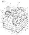
- Figure 1 illustrates a flexible tank according to the present invention associated with a containing framework,
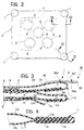
- Figure 2 is a schematic elevational view of flexible containers forming part of the tank of Figure 1,
- Figure 3 is a partially-sectioned side elevational view taken on the line III-III of Figure 2,
- Figure 4 is a view similar to Figure 3 showing a detail indicated by the arrows IV-IV in Figure 2,
- Figure 5 is a perspective view of the framework which surrounds the tank of the invention,
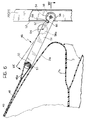
- Figure 6 is a partially-sectioned side elevational view of a device for retaining the tank in the framework, indicated by the arrow VI in Figure 1, and
- Figure 7 is a partially-sectioned elevational view of the device of Figure 6.
- With reference to the drawings, a flexible tank for liquids is generally indicated 1. It includes a plurality of superposed
flexible containers 2 which, in the present embodiment, are substantially rectangular in shape. - Each
container 2 includes anupper sheet 2a and alower sheet 2b joined together around their peripheries by a weld 3 achieved, for example, by high-frequency vibrations. - The
sheet 2a is more extensive than thesheet 2b and includes projectingportions 3a which can be folded so as to enclose the edges of the lessextensive sheet 2b. The projectingportions 3a are shaped so as to enclose the edges of asheet 2b leaving the vertices free. In order to achieve the welding 3 joining each of thesheets 2a to therespective sheet 2b, metal strips (not illustrated in the drawings) must be provided, the strips having a length approximately corresponding to the length of the sides of the lessextensive sheet 2b and a width at least equal to the width of the weld which is wished to obtain. These metal strips are arranged along the sides of the less extensive sheet and then the twosheets portions 3a of thesheet 2a over the edges of thesheet 2b leaving apertures at the vertices of the container. The welding 3 is then effected so as to join the projectingportions 3a to the edge portions of therespective sheet 2b in correspondence with the metal strips. Subsequently the metal strips are withdrawn through the open vertices of the container. The open vertices of the container are then sealed in the manner which will be explained more fully in the description below. - Each of the
containers 2 of the tank is made so that the pressure exerted by the liquid therein generates tangential forces between thesheets - Each
flexible container 2 is welded to the adjacent containers by aweld line 4 inside the weld lines 3. -
Apertures 6 are formed inside theweld line 4 in each of thesheets adjacent containers 2, there being no less than five apertures as illustrated in Figure 2, each of these apertures having anedge 8 withprojections 9 which extend perpendicular to the sheets and enable the sheets to be spaced from each other so as to facilitate the filling of thecontainers 2. Theapertures 6 in thecontainers 2 of the tank are arranged so as to be vertically aligned with each other. -
Seal elements 11 are provided at each vertex of thecontainers 2 and enable each container to be sealed after the welding of thesheets - Each
element 11 includes twoouter parts 11a located against the outer faces of thesheets inner portion 11b interposed between thesheet 2a and thesheet 2b of eachcontainer 2. Theelements 11 are welded to the vertices of each container, for example by high-frequency welding. - The
tank 1 is surrounded by a framework 15 (Figures 1 and 5) which comprises a rigid structure formed fromupper cross-members lower cross-members uprights 20. -
Pivotable frames 22 are articulated at 21 to the outwardly facing sides of thecross-members cross-members 25 which, in the open condition of theframes 22, can be arranged as extensions of thecross-members cross-members 25 being rigidly interconnected byuprights 27. - The
uprights framework 15, in its open configuration, to allow access to the hollow interiors of the profiled sections for purposes which will be clarified below. Close to thearticulations 21 of theframes 22 are anchoringdevices 23 for clamping theframes 22 to the fixed structure of theframework 15 in their open position. Thesedevices 23 for example comprise screws adapted to engage corresponding holes formed in thecross-members 25. - The
pivotable frames 22 are particularly useful, for example, when thetank 1, with itsframework 15, must be introduced into a space provided with a narrow opening. In this case, theframework 15 is first inserted through the opening with theframes 22 folded, afterwards theframes 22 are moved into their open position and clamped in these position by means of theanchoring devices 23. - Subsequently the
tank 1 is inserted through the narrow opening into theframework 15. - An
assembly 30 is rigidly fixed to the top of the framework 15 (Figure 1) and includes a rotatable drum on which is wound aflexible tube 32 connected by aconnector 33 to a motor-pump unit 35 also connected rigidly to the top of theframework 15 and to which are connected, in known manner, a pair ofducts lowermost container 2 of thetank 1. - The
ducts tank 1; more particularly, one of these acts as an air vent during filling of the tank through the other duct while, during emptying of the tank, it is used for discharging liquid to the exterior. - On the upper face of the
uppermost container 2 of thetank 1 is anautomatic valve 42 which enables any air present in thetank 1 to escape. - A
cap 43 is also provided on the upper face and can be used to facilitate refilling of thetank 1. - The
upper container 2 of thetank 1 has associatedretaining devices 46 whose function is to limit both transverse movements and vertical movements of thetank 1 when it is located within theframework 15. Thedevices 46 are particularly useful when thetank 1 is partially full and when it is subjected to oscillations in transport. In fact, in this case, it is possible to adjust the position of the upper face of theupper container 2 of the tank relative to theuprights devices 46. -
Flexible belts 48 each having aneyelet 48a at one end are welded at 49 to the upper face of theuppermost container 2 of thetank 1. Eacheyelet 48a is traversed by apin 50 which engages a through-hole 53 formed in a rigid stabilisingarm 51. The end of thearm 51 opposite that having thehole 53 is inserted into the cavity in therespective upright arm 51 within theupright hole 54 formed transversely thereto and to the upright and engaged by apin 56 which, on opposite sides of thearm 51, carries twowheels 58 of deformable material, for example an elastomer or the like. Thewheels 58 have radially-outerconcave surfaces 59 so as to generate less friction during their rolling within theupright - A substantially square annulus, or ring, 62 is articulated at 64 to each of the
arms 51 while itsside 66 opposite that which is engaged at 64 can pivot between an inactive position, for example located above thearm 51 and nearer the hole 53 (shown in chain line in Figure 7), to an active position in which theside 66 engages atransverse groove 68 in thearm 51 close to the hole 54 (continuous line in Figure 7). - Two
wheels 58a, of the same type as thewheels 58, are located in correspondence with thearticulation 64, also on opposite sides of thearm 51, the wheels being traversed by thering 62 and serving as spacers to keep thering 62 in a substantially centred position with respect to thearm 51. - In operation of the
device 46, when the tank is full of liquid, for example even only partly, thering 62 is in its inactive position described above. - When a downward force is exerted on each of the
arms 51, thebelts 48 are tensioned. Thearms 51 being kept in this position, thering 62 is rotated so as to engage the correspondinggroove 68 such that theoutermost side 66 of thering 62 contacts the wall of the upright 22 (or 27) facing thetank 1, preventing movement of thedevice 46 along the respective upright. In this position, thewheels 58 of deformable material located within the uprights 22 (or 27) deform and, in particular, their radiallyoutermost parts 59 having the outwardly concave surfaces which are more easily deformable, deform. The clamping of thedevices 46 enables the upper face of theuppermost container 2 of thetank 1 to be secured extremely effectively so as to limit upward and transverse movements of the tank relative to theframework 15, giving the tank-framework system the maximum stability.
Claims (14)
- A flexible tank for liquids, of the type comprising:- a plurality of superposed flexible containers (2) which are substantially polygonal in plan, each being constituted by a pair of superposed flexible sheets (2a, 2b) sealed together along their peripheries,- each container (2) being welded to the adjacent containers (2) along a weld line (4) inside the periphery of the sheets (2a, 2b),- the interiors of the containers (2) communicating with each other through a series of holes (6) formed in the sheets (2a, 2b) inside the weld line (4) and vertically aligned with each other,- the interior of one of the containers (2) communicating with the exterior of the tank (1) through connector means (37, 39),characterised in that one (2a) of the flexible sheets (2a, 2b) constituting each of the individual containers (2) is more extensive than the other sheet (2b) and has projecting portions (3a) folded over the edges of the less extensive sheet (2b) so as to leave its vertices free, the projecting portions (3a) being welded to the edge portions of the less extensive sheet (2b) and, also, each container (2) being provided with seal elements (11) welded at its vertices.
- A tank according to Claim 1, characterised in that each of the seal elements (11) welded to the vertices of each container (2) has an inner portion (11b) interposed between the more extensive sheet (2a) and the less extensive sheet (2b) and two outer portions (11a) located outside the more extensive sheet (2a) and the less extensive sheet (2b) respectively, these outer portions (11a) and the inner portion (11b) being connected together.
- A tank according to Claim 2, characterised in that the connector means comprise a first duct (37) and a second duct (39) both connected to the lowermost container (2), the first duct (37) acting as an air vent during filling of the tank (1) effected through the second connector (39) and as an outlet for liquid during emptying of the tank (1).
- A tank according to Claim 3, characterised in that the uppermost container (2) has an automatic valve (42) for allowing air to flow out of the tank (1).
- A tank according to any one of Claims 1 to 4, characterised in that the tank has a framework (15) which surrounds the tank (1) and includes a plurality of uprights (20, 27) and an adjustable retaining device (46) for anchoring the upper face of the upper container (2) of the tank (1) to the framework (15), the device (46) including tie connecting means (48, 49, 50, 51) each having one end connected to the container (2) and its opposite end slidably engaged with a respective upright (20, 27) forming part of the framework (15).
- A tank according to Claim 5, characterised in that the tie connecting means include a belt (48), each disposed in correspondence with an upright (20, 27) of the framework (15), an arm (51) being articulated to each of the belts (48) and adapted to engage slidingly with a respective upright (20, 27).
- A tank according to Claim 6, characterised in that the uprights (20, 27) are hollow and have a longitudinal respective slot (52) facing the tank (1), said slot (52) being traversed by one end of a respective stabilising arm (51), and in that the guide means are wheels (59) which can run within the uprights (20, 27), the wheels (58) being articulated at the opposite end of the respective stabilizing arm (51) from the belt (48).
- A tank according to Claim 7, characterised in that the stabilising arms (51) include means (62, 68) for adjusting the height of the tank (1) relative to the framework (15).
- A tank according to Claim 8, characterised in that the means for adjusting the height of the tank (1) include a clamping ring (62) articulated to the stabilising arm (51), the ring (62) being pivotable between an inactive position and an active position in which it engages a groove (68) in the respective stabilising arm (51) so as to interfere with the respective upright (20, 27) whereby movements of the top of the tank (1) longitudinally of the respective upright (20, 27) are prevented.
- A tank according to Claim 9, characterised in that the wheels (58) are resiliently deformable.
- A tank according to Claim 10, characterised in that the radially-outer surfaces of the wheels (58) are outwardly concave (59).
- A tank according to Claim 5, characterised in that the framework (15) includes pivotable frames (22) hinged to a ridged structure (18a, 18b, 19a, 19b, 20).
- A process for the manufacture of a flexible tank for liquids of the type comprising at least one flexible container (2) having a substantially polygonal shape in plan and constituted by a pair of superposed flexible sheets (2a, 2b) sealed together along their peripheries, characterised in that it includes the following steps:- providing the two sheets (2a, 2b), one of which (2a) is more extensive than the other sheet (2b) and has portions (3a) which project beyond the less extensive sheet (2b), the projecting portions (3a) being able to be disposed in correspondence with the edges of the less extensive sheet (2b) leaving the vertices free,- providing metallic strips of a length corresponding substantially to the sides of the less extensive sheet (2b),- superposing the said sheets (2a, 2b) with the metal strips interposed between them along the edges of the less extensive sheet (2b),- folding the projecting portions (3a) of the more extensive sheet (2a) over the edges of the less extensive sheet (2b),- welding the projecting portions (3a) of the more extensive sheet (2a) along the edges of the less extensive sheet (2b) in correspondence with the metal strips, leaving the vertices of the container (2) open,- removing the metal strips through the vertices of the container (2), and- closing the vertices of the container (2) by welding a seal element (11) to each of them.
- A process according to Claim 13, characterised in that each of the seal elements (11) comprises an inner portion (11b) adapted to be interposed between the more extensive sheet (2a) and the less extensive sheet (2b) and a pair of outer portions (11a) adapted to be located outside the more extensive sheet (2a) and the less extensive sheet (2b) respectively, the outer portions (11a) and the inner portion (11b) being connected together.
Applications Claiming Priority (2)
| Application Number | Priority Date | Filing Date | Title |
|---|---|---|---|
| ITTO920576 | 1992-07-09 | ||
| ITTO920576A IT1257260B (en) | 1992-07-09 | 1992-07-09 | FLEXIBLE TANK FOR LIQUIDS AND PROCEDURE FOR ITS REALIZATION. |
Publications (2)
| Publication Number | Publication Date |
|---|---|
| EP0578033A1 EP0578033A1 (en) | 1994-01-12 |
| EP0578033B1 true EP0578033B1 (en) | 1994-11-02 |
Family
ID=11410587
Family Applications (1)
| Application Number | Title | Priority Date | Filing Date |
|---|---|---|---|
| EP93109766A Expired - Lifetime EP0578033B1 (en) | 1992-07-09 | 1993-06-18 | A flexible tank for liquids and a process for its manufacture |
Country Status (5)
| Country | Link |
|---|---|
| EP (1) | EP0578033B1 (en) |
| AT (1) | ATE113557T1 (en) |
| DE (1) | DE69300023T2 (en) |
| ES (1) | ES2063593T3 (en) |
| IT (1) | IT1257260B (en) |
Families Citing this family (2)
| Publication number | Priority date | Publication date | Assignee | Title |
|---|---|---|---|---|
| DE202008015117U1 (en) | 2008-06-05 | 2009-02-19 | Airmatic Gesellschaft für Umwelt und Technik mbH | Flexible liquid container with arbitrarily shaped container body |
| DE202010007865U1 (en) | 2010-06-11 | 2010-10-07 | Airmatic Gesellschaft für Umwelt und Technik mbH | Fire engine |
Family Cites Families (2)
| Publication number | Priority date | Publication date | Assignee | Title |
|---|---|---|---|---|
| US3724497A (en) * | 1971-03-04 | 1973-04-03 | Metzeler Ag | Storage system for gaseous fluids and the like |
| CH657597A5 (en) * | 1983-06-15 | 1986-09-15 | Prometeo Srl | FLEXIBLE TANK FOR LIQUIDS. |
-
1992
- 1992-07-09 IT ITTO920576A patent/IT1257260B/en active IP Right Grant
-
1993
- 1993-06-18 EP EP93109766A patent/EP0578033B1/en not_active Expired - Lifetime
- 1993-06-18 AT AT93109766T patent/ATE113557T1/en not_active IP Right Cessation
- 1993-06-18 DE DE69300023T patent/DE69300023T2/en not_active Expired - Fee Related
- 1993-06-18 ES ES93109766T patent/ES2063593T3/en not_active Expired - Lifetime
Also Published As
| Publication number | Publication date |
|---|---|
| ITTO920576A1 (en) | 1994-01-09 |
| ITTO920576A0 (en) | 1992-07-09 |
| ATE113557T1 (en) | 1994-11-15 |
| EP0578033A1 (en) | 1994-01-12 |
| IT1257260B (en) | 1996-01-10 |
| ES2063593T3 (en) | 1995-01-01 |
| DE69300023D1 (en) | 1994-12-08 |
| DE69300023T2 (en) | 1995-03-09 |
Similar Documents
| Publication | Publication Date | Title |
|---|---|---|
| AU2002251961B2 (en) | Large volume flexible container | |
| DE69837812T2 (en) | DISPENSING PACKAGING AND MANUFACTURING METHOD | |
| AU2002251957B2 (en) | Gas permeable sterile closure | |
| CA2441047C (en) | Container support | |
| EP0905046B1 (en) | Flexible package and dispensing device for a liquid product | |
| AU2002251961A1 (en) | Large volume flexible container | |
| JPH09132238A (en) | Modular spill deck | |
| CA1141714A (en) | Straddle crane apparatus | |
| US6032818A (en) | Liner | |
| AU2002248444A1 (en) | Container support | |
| AU2002251957A1 (en) | Gas permeable sterile closure | |
| CA1302971C (en) | Foil bag | |
| EP0578033A1 (en) | A flexible tank for liquids and a process for its manufacture | |
| FI88904C (en) | Bottom seam for bucket | |
| EP0559290B1 (en) | Apparatus for sealing containers | |
| EP0579334B1 (en) | Adjustable packaging machine | |
| US4750846A (en) | Container for transport and storage of bulk material | |
| EP0564717B1 (en) | Collapsible bulk or liquid container | |
| JPS6355038A (en) | Molding equipment for content filling vessel | |
| CN109649831B (en) | Liquid filling system and method and auxiliary filling equipment | |
| CN209939408U (en) | Liquid filling system and auxiliary filling equipment | |
| EP0270717A1 (en) | Method of manufacturing a flexible disposable container for sterile products, and container so realised | |
| AU2006207865B2 (en) | A hanger system for supporting a flexible medical container in a support container | |
| CA1188267A (en) | Closure for flexible containers | |
| EP1116669B1 (en) | Inflatable packaging material |
Legal Events
| Date | Code | Title | Description |
|---|---|---|---|
| PUAI | Public reference made under article 153(3) epc to a published international application that has entered the european phase |
Free format text: ORIGINAL CODE: 0009012 |
|
| AK | Designated contracting states |
Kind code of ref document: A1 Designated state(s): AT BE CH DE DK ES FR GB GR IE IT LI LU MC NL PT SE |
|
| 17P | Request for examination filed |
Effective date: 19931216 |
|
| 17Q | First examination report despatched |
Effective date: 19940328 |
|
| GRAA | (expected) grant |
Free format text: ORIGINAL CODE: 0009210 |
|
| AK | Designated contracting states |
Kind code of ref document: B1 Designated state(s): AT BE CH DE DK ES FR GB GR IE IT LI LU MC NL PT SE |
|
| PG25 | Lapsed in a contracting state [announced via postgrant information from national office to epo] |
Ref country code: NL Effective date: 19941102 Ref country code: MC Free format text: LAPSE BECAUSE OF NON-PAYMENT OF DUE FEES Effective date: 19941102 Ref country code: DK Effective date: 19941102 Ref country code: BE Effective date: 19941102 Ref country code: AT Effective date: 19941102 |
|
| REF | Corresponds to: |
Ref document number: 113557 Country of ref document: AT Date of ref document: 19941115 Kind code of ref document: T |
|
| ITF | It: translation for a ep patent filed | ||
| REG | Reference to a national code |
Ref country code: IE Ref legal event code: FG4D Free format text: 61856 |
|
| ET | Fr: translation filed | ||
| REF | Corresponds to: |
Ref document number: 69300023 Country of ref document: DE Date of ref document: 19941208 |
|
| REG | Reference to a national code |
Ref country code: ES Ref legal event code: FG2A Ref document number: 2063593 Country of ref document: ES Kind code of ref document: T3 |
|
| PG25 | Lapsed in a contracting state [announced via postgrant information from national office to epo] |
Ref country code: SE Effective date: 19950202 |
|
| REG | Reference to a national code |
Ref country code: GR Ref legal event code: FG4A Free format text: 3014736 |
|
| SC4A | Pt: translation is available |
Free format text: 941107 AVAILABILITY OF NATIONAL TRANSLATION |
|
| NLV1 | Nl: lapsed or annulled due to failure to fulfill the requirements of art. 29p and 29m of the patents act | ||
| PG25 | Lapsed in a contracting state [announced via postgrant information from national office to epo] |
Ref country code: LU Free format text: LAPSE BECAUSE OF NON-PAYMENT OF DUE FEES Effective date: 19950630 Ref country code: IE Free format text: LAPSE BECAUSE OF NON-PAYMENT OF DUE FEES Effective date: 19950630 |
|
| PLBE | No opposition filed within time limit |
Free format text: ORIGINAL CODE: 0009261 |
|
| STAA | Information on the status of an ep patent application or granted ep patent |
Free format text: STATUS: NO OPPOSITION FILED WITHIN TIME LIMIT |
|
| 26N | No opposition filed | ||
| PGFP | Annual fee paid to national office [announced via postgrant information from national office to epo] |
Ref country code: ES Payment date: 19960628 Year of fee payment: 4 |
|
| PGFP | Annual fee paid to national office [announced via postgrant information from national office to epo] |
Ref country code: PT Payment date: 19960717 Year of fee payment: 4 |
|
| PGFP | Annual fee paid to national office [announced via postgrant information from national office to epo] |
Ref country code: CH Payment date: 19960724 Year of fee payment: 4 Ref country code: DE Payment date: 19960724 Year of fee payment: 4 |
|
| PGFP | Annual fee paid to national office [announced via postgrant information from national office to epo] |
Ref country code: GR Payment date: 19960731 Year of fee payment: 4 |
|
| PG25 | Lapsed in a contracting state [announced via postgrant information from national office to epo] |
Ref country code: GB Free format text: LAPSE BECAUSE OF NON-PAYMENT OF DUE FEES Effective date: 19970618 |
|
| PG25 | Lapsed in a contracting state [announced via postgrant information from national office to epo] |
Ref country code: ES Free format text: LAPSE BECAUSE OF EXPIRATION OF PROTECTION Effective date: 19970619 |
|
| PG25 | Lapsed in a contracting state [announced via postgrant information from national office to epo] |
Ref country code: LI Free format text: LAPSE BECAUSE OF NON-PAYMENT OF DUE FEES Effective date: 19970630 Ref country code: GR Free format text: LAPSE BECAUSE OF NON-PAYMENT OF DUE FEES Effective date: 19970630 Ref country code: CH Free format text: LAPSE BECAUSE OF NON-PAYMENT OF DUE FEES Effective date: 19970630 |
|
| PG25 | Lapsed in a contracting state [announced via postgrant information from national office to epo] |
Ref country code: PT Effective date: 19971231 |
|
| GBPC | Gb: european patent ceased through non-payment of renewal fee |
Effective date: 19970618 |
|
| REG | Reference to a national code |
Ref country code: CH Ref legal event code: PL |
|
| PG25 | Lapsed in a contracting state [announced via postgrant information from national office to epo] |
Ref country code: DE Free format text: LAPSE BECAUSE OF NON-PAYMENT OF DUE FEES Effective date: 19980303 |
|
| REG | Reference to a national code |
Ref country code: PT Ref legal event code: MM4A Free format text: LAPSE DUE TO NON-PAYMENT OF FEES Effective date: 19971231 |
|
| PGFP | Annual fee paid to national office [announced via postgrant information from national office to epo] |
Ref country code: FR Payment date: 19980630 Year of fee payment: 6 |
|
| PG25 | Lapsed in a contracting state [announced via postgrant information from national office to epo] |
Ref country code: FR Free format text: THE PATENT HAS BEEN ANNULLED BY A DECISION OF A NATIONAL AUTHORITY Effective date: 19990630 |
|
| REG | Reference to a national code |
Ref country code: FR Ref legal event code: ST |
|
| REG | Reference to a national code |
Ref country code: ES Ref legal event code: FD2A Effective date: 20010201 |
|
| PG25 | Lapsed in a contracting state [announced via postgrant information from national office to epo] |
Ref country code: IT Free format text: LAPSE BECAUSE OF NON-PAYMENT OF DUE FEES;WARNING: LAPSES OF ITALIAN PATENTS WITH EFFECTIVE DATE BEFORE 2007 MAY HAVE OCCURRED AT ANY TIME BEFORE 2007. THE CORRECT EFFECTIVE DATE MAY BE DIFFERENT FROM THE ONE RECORDED. Effective date: 20050618 |