EP0577942A1 - Filter means - Google Patents
Filter means Download PDFInfo
- Publication number
- EP0577942A1 EP0577942A1 EP93107238A EP93107238A EP0577942A1 EP 0577942 A1 EP0577942 A1 EP 0577942A1 EP 93107238 A EP93107238 A EP 93107238A EP 93107238 A EP93107238 A EP 93107238A EP 0577942 A1 EP0577942 A1 EP 0577942A1
- Authority
- EP
- European Patent Office
- Prior art keywords
- filter
- filter material
- cover plates
- endless belt
- filter means
- Prior art date
- Legal status (The legal status is an assumption and is not a legal conclusion. Google has not performed a legal analysis and makes no representation as to the accuracy of the status listed.)
- Granted
Links
Images


Classifications
-
- B—PERFORMING OPERATIONS; TRANSPORTING
- B01—PHYSICAL OR CHEMICAL PROCESSES OR APPARATUS IN GENERAL
- B01D—SEPARATION
- B01D33/00—Filters with filtering elements which move during the filtering operation
- B01D33/04—Filters with filtering elements which move during the filtering operation with filtering bands or the like supported on cylinders which are impervious for filtering
-
- B—PERFORMING OPERATIONS; TRANSPORTING
- B01—PHYSICAL OR CHEMICAL PROCESSES OR APPARATUS IN GENERAL
- B01D—SEPARATION
- B01D33/00—Filters with filtering elements which move during the filtering operation
- B01D33/056—Construction of filtering bands or supporting belts, e.g. devices for centering, mounting or sealing the filtering bands or the supporting belts
-
- B—PERFORMING OPERATIONS; TRANSPORTING
- B01—PHYSICAL OR CHEMICAL PROCESSES OR APPARATUS IN GENERAL
- B01D—SEPARATION
- B01D33/00—Filters with filtering elements which move during the filtering operation
- B01D33/333—Filters with filtering elements which move during the filtering operation with individual filtering elements moving along a closed path
Definitions
- the invention relates to a filter medium consisting of a drivable endless belt which can be guided around deflection rollers provided with at least one drive ring, which has at least one filter material and which is formed from individual cover plates which are provided on both sides with an angular end piece in the running direction of the endless belt, the can be connected to the next end piece facing it, the end pieces connected to one another forming driver elements which protrude beyond the endless belt and each have at their free ends a driving pin which is part of a guide part.
- Such filter media are used in belt filter systems, as are described, for example, in DE-PS 39 10 930 and which are used to filter a liquid from a suspension.
- a generic filter medium is described in US Pat. No. 3,288,296.
- the individual cover plates which cover a container of the belt filter system for the filtrate when this container is passed over and therefore separate from the suspension to be cleaned, are formed directly from the filter material itself, which, in segment-like fashion, forms the endless belt.
- the two angularly connected to each other via an intermediate rail End pieces are each encompassed by a U-profile, so that driver elements protruding beyond the endless belt are formed, which serve to remove dirt, in particular a so-called oblique discharge in belt filter systems.
- the known driver elements each have at their free ends a driving pin which is fixedly connected to a connecting link of a chain which forms a guide part for moving the endless belt.
- the two chains bordering the endless belt are driven by a deflection roller, which for this purpose has a drive ring in the form of a toothed ring at the end.
- Another filter medium is known from US Pat. No. 1,890,251, which is not composed of individual segments, but rather forms a continuous endless belt.
- the known filter belt has rod-like driver elements on its inside, which are provided at the end with a driving roller. These known driver elements do not serve to remove dirt, but rather form the guide part for moving the endless belt with the respective driving rollers.
- the rod-like driver elements have, at their free ends, an engagement area for the engagement of a drive ring, which for this purpose has tooth-like projections which are curved along its outer circumference.
- the invention has for its object to provide a filter medium which does not have the disadvantages described.
- a relevant task is solved in its entirety with the features of claim 1.
- the guide part has at least one castor and a T-shaped fork piece, the fork ends of which comprise a pair of interconnected end pieces and that the respective drive ring has circumferential recesses for the engagement with the driving pins are provided, a reliable guidance of the endless belt is ensured via the castors, so that it cannot, for example, stand out from the mentioned container of the filter system. This prevents unwanted contamination of the filtrate.
- the end pieces projecting in pairs facing one another on the top of the endless belt not only connect the individual cover plates to one another, but can simultaneously be used as driver elements for the removal of dirt.
- the drive design according to the invention ensures smooth operation, which protects the filter medium. If parts of the filter medium are dirty, only the filtering cover plates in question need to be replaced and the The system is again ready for operation.
- the filter material is received between the cover plates with mutually adjacent passages which are covered by the filter material.
- the cover plates protect the possibly sensitive filter material from damage.
- the cover plates have thermoplastically processable plastics which are particularly simple and inexpensive to process.
- the plastic preferably consists of a polyester with urethane or a polyvinyl chloride or a combination of these materials.
- the opposing cover plates and the respective filter material between the receiving cover plates are thermally welded together. This makes it possible to produce a particularly secure bond between the individual components of the filter medium.
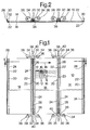
- the filter means consists of a drivable endless belt, designated as a whole by 10, of which three segments are shown in FIGS. 1 and 2. 3 and 4 in particular, each segment has a filter material 12 which is accommodated between two cover plates with mutually opposite passages 16 which are covered by the filter material 12. For the sake of simplicity, not all passages 16 are shown in FIGS. 1 and 3.
- the filter material of the filter medium according to the invention consists of a fine-mesh or fine-pored grid and / or sieve and / or fabric made of metal and / or plastic and / or textiles.
- a metal wire mesh is used as filter material 12, which is sold by Spörl GmbH & Co KG under the trademark "BETAMESH".
- This metal wire filter fabric BETAMESH can be made from all weavable materials, but mainly consists of 1.4401 / AISI 316 stainless steel wire.
- the absolute filter fineness of this metal wire filter fabric is, depending on the application, between 15 and 89 ⁇ m.
- the filter fabric 12 forms a rectangular mat and is completely surrounded by the rectangular cover plates 14 on the edge. For the sake of simplicity, not all passages 16 are shown covered with the filter material 12 in FIGS. 1 and 3.
- the passages 16 are arranged in series one behind the other and side by side and have an elongated shape which, seen in the direction of travel 18, end on both sides in a circular end.
- the selected arrangement provides a correspondingly large cross-sectional area for the filtering process.
- the respective cover plate 14 has a cross-stiff polyester fabric in warp and weft with two fabric layers.
- the support side facing the viewer of FIGS. 1 and 3 is coated with approx. 0.3 mm urethane, whereas that Viewer facing away from the running side of the endless belt 10 is urethane impregnated.
- To produce the composite of cover plates 14 with filter material 12 the latter is exposed to a welding temperature of approximately 170 ° C. with a contact pressure of 7 bar, the holding time being 5 minutes.
- the respective segment is flexible and can be deflected accordingly along deflection rollers in a belt filter system (not shown).
- the respective cover plate 14 can also consist of polyvinyl chloride.
- the respective cover plate 14 Viewed in the running direction 18 of the endless belt 10, the respective cover plate 14 is provided on both sides with an end piece 20 which is connected to the next end piece 20 facing it (FIG. 1).
- the respective end piece 20 forms a right-angled metal strip, the cross-sectional shape (FIG. 4) of which can be obtained from a rectangular sheet metal blank by appropriate bending.
- Each end piece 20 forms two leg pieces 22 for receiving the supporting side of a segment in the form of the cover plate 14 shown at the top in FIG. 4, which delimit a type of clamping gap into which the upper cover plate 14 can be fixed with its edge-side region.
- the interconnected end pieces 20 form driver elements 26 which protrude beyond the endless belt 10 and which on the one hand serve to discharge dirt and on the other hand join the individual segments to form the endless belt 10.
- a screw connection (not shown) is also provided, of which the through bore 28 can be seen in FIG.
- a T-shaped fork piece 30 Transverse to the direction 18 is at the free ends of the endless belt 10 at the end a T-shaped fork piece 30 is arranged, the fork ends of which comprise a pair of interconnected end pieces 20 and are firmly connected to these by means of a screw connection 32 (FIG. 2).
- the fork piece 30 has two extensions 34 which form a "V" with each other and are each connected at the end to a rotatable castor 36.
- These guide rollers 36 engage under a corresponding guide rail (not shown) within the belt filter system for guiding the endless belt 10.
- Extensions 34 and castors 36 are therefore part of a guide part 38, each of which has a driving pin 40, which protrudes from the boundary of the endless belt 10 to the outside.
- the respective driving pin 40 can be brought into engagement with a drive ring 42, as shown in FIG.
- the drive ring 42 which is permanently connected at the end to a cylindrical deflection roller (not shown) for the endless belt 10, has four recesses 44 on the circumference and at equal radial distances from one another, which carry the respective driving pin 40 for driving the endless belt 10 .
Abstract
Description
Die Erfindung betrifft ein Filtermittel, bestehend aus einem antreibbaren Endlosband, das um mit mindestens einem Antriebskranz versehene Umlenkrollen führbar ist, das mindestens ein Filtermaterial aufweist und das aus einzelnen Abdeckplatten gebildet ist, die in Laufrichtung des Endlosbandes beidseitig mit einem winkelförmigen Endstück versehen sind, das mit dem nächsten ihm zugewandten Endstück verbindbar ist, wobei die miteinander verbundenen Endstücke über das Endlosband hinausstehende Mitnehmerelemente bilden, die an ihren freien Enden jeweils einen Mitnahmezapfen aufweisen, der Teil eines Führungsteiles ist.The invention relates to a filter medium consisting of a drivable endless belt which can be guided around deflection rollers provided with at least one drive ring, which has at least one filter material and which is formed from individual cover plates which are provided on both sides with an angular end piece in the running direction of the endless belt, the can be connected to the next end piece facing it, the end pieces connected to one another forming driver elements which protrude beyond the endless belt and each have at their free ends a driving pin which is part of a guide part.
Dahingehende Filtermittel finden bei Bandfilteranlagen Verwendung, wie sie beispielsweise in der DE-PS 39 10 930 beschrieben sind und die zum Abfiltrieren einer Flüssigkeit aus einer Suspension dienen.Such filter media are used in belt filter systems, as are described, for example, in DE-PS 39 10 930 and which are used to filter a liquid from a suspension.
In der US-PS 3,288,296 ist ein gattungsgleiches Filtermittel beschrieben. Bei diesem bekannten Filtermittel sind die einzelnen Abdeckplatten, die ein Behältnis der Bandfilteranlage für das Filtrat beim Überfahren dieses Behältnisses abdecken und mithin von der zu reinigenden Suspension trennen, unmittelbar aus dem Filtermaterial selbst gebildet, das segmentartig zusammengesetzt das Endlosband bildet. Die beiden miteinander über eine Zwischenschiene verbundenen winkelförmigen Endstücke sind von einem U-Profil jeweils umgriffen, so daß über das Endlosband hinausstehende Mitnehmerelemente gebildet sind, die dem Schmutzaustrag, insbesondere einem sogenannten Schrägaustrag bei Bandfilteranlagen, dienen.A generic filter medium is described in US Pat. No. 3,288,296. In this known filter medium, the individual cover plates, which cover a container of the belt filter system for the filtrate when this container is passed over and therefore separate from the suspension to be cleaned, are formed directly from the filter material itself, which, in segment-like fashion, forms the endless belt. The two angularly connected to each other via an intermediate rail End pieces are each encompassed by a U-profile, so that driver elements protruding beyond the endless belt are formed, which serve to remove dirt, in particular a so-called oblique discharge in belt filter systems.
Die bekannten Mitnehmerelemente weisen an ihren freien Enden jeweils einen Mitnahmezapfen auf, der fest mit einem Verbindungsglied einer Kette verbunden ist, die ein Führungsteil zum Bewegen des Endlosbandes bildet. Die beiden das Endlosband randseitig begrenzenden Ketten werden von einer Umlenkrolle angetrieben, die hierfür endseitig jeweils einen Antriebskranz in Form eines Zahnkranzes aufweist.The known driver elements each have at their free ends a driving pin which is fixedly connected to a connecting link of a chain which forms a guide part for moving the endless belt. The two chains bordering the endless belt are driven by a deflection roller, which for this purpose has a drive ring in the form of a toothed ring at the end.
Dahingehende Kettentriebe unterliegen einem Verschleiß und es kommt relativ häufig zu einem Versagen der Kette, was zu ungewollten Stillstandszeiten beim Betrieb der Filteranlagen führt. Insbesondere das Anfahren der jeweiligen Anlage mit dem bekannten Filtermittel geschieht durch den Kettentrieb bedingt nicht völlig ruckfrei, so daß es im randseitigen Bereich des Filtermaterials zu Aufwerfungen kommen kann und damit zu einem Eindringen der ungefilterten Suspension in das angesprochene Behältnis für das Filtrat, was das Filtrierergebnis und die Filtrierleistung beeinträchtigt.Such chain drives are subject to wear and the chain fails relatively frequently, which leads to undesired downtimes when operating the filter systems. In particular, the start-up of the respective system with the known filter medium is not completely jerk-free due to the chain drive, so that it can be raised in the edge region of the filter material and thus penetrate the unfiltered suspension into the mentioned container for the filtrate, which results in the filtering result and affects filtering performance.
Durch die US-PS 1,890,251 ist ein anderes Filtermittel bekannt, das nicht aus einzelnen Segmenten zusammengesetzt ist, sondern vielmehr ein durchgehendes Endlosband bildet. Das bekannte Filterband weist auf seiner Innenseite stabartige Mitnehmerelemente auf, die endseitig mit einer Fahrrolle versehen sind. Diese bekannten Mitnehmerelemente dienen nicht dem Schmutzaustrag, sondern bilden mit den jeweiligen Fahrrollen das Führungsteil für das Bewegen des Endlosbandes. Die stabartigen Mitnehmerelemente weisen zu ihren freien Enden hin einen Eingriffsbereich für den Eingriff eines Antriebskranzes auf, der längs seines Außenumfanges hierfür gebogene zahnartige Vorsprünge hat.Another filter medium is known from US Pat. No. 1,890,251, which is not composed of individual segments, but rather forms a continuous endless belt. The known filter belt has rod-like driver elements on its inside, which are provided at the end with a driving roller. These known driver elements do not serve to remove dirt, but rather form the guide part for moving the endless belt with the respective driving rollers. The rod-like driver elements have, at their free ends, an engagement area for the engagement of a drive ring, which for this purpose has tooth-like projections which are curved along its outer circumference.
Ist dieses bekannte Filtermittel an einer Stelle, beispielsweise durch starke Verschmutzung, unbrauchbar geworden, ist das gesamte Filtermittel gegen ein neues auszutauschen. Ferner können durch die auftretenden Beanspruchungen beim Betrieb der Anlage die vorstehenden Zähne an den Antriebskränzen brechen, was wiederum zu ungewollten Stillstandszeiten der Anlage führt.If this known filter medium becomes unusable at one point, for example due to heavy contamination, the entire filter medium must be replaced with a new one. Furthermore, due to the stresses that occur during operation of the system, the protruding teeth on the drive rings can break, which in turn leads to undesired downtimes of the system.
Ausgehend von diesem Stand der Technik liegt der Erfindung die Aufgabe zugrunde, ein Filtermittel zu schaffen, das die beschriebenen Nachteile nicht aufweist. Eine dahingehende Aufgabe wird mit den Merkmalen des Anspruches 1 in seiner Gesamtheit gelöst.Based on this prior art, the invention has for its object to provide a filter medium which does not have the disadvantages described. A relevant task is solved in its entirety with the features of claim 1.
Dadurch, daß bei einem Filtermittel mit den Merkmalen des Oberbegriffes des Anspruches 1 gemäß seinem kennzeichnenden Teil das Führungsteil mindestens eine Fahrrolle und ein T-förmiges Gabelstück aufweist, dessen Gabelenden ein Paar miteinander verbundener Endstücke umfaßt und daß der jeweilige Antriebskranz umfangsseitig Ausnehmungen aufweist, die für den Eingriff mit den Mitnahmezapfen vorgesehen sind, ist über die Fahrrollen eine sichere Führung des Endlosbandes gewährleistet, so daß dieses sich beispielsweise von dem angesprochenen Behältnis der Filteranlage nicht abheben kann. Ungewollte Verschmutzungen des Filtrates sind somit vermieden. Die auf der Oberseite des Endlosbandes vorstehenden einander paarweise zugewandten Endstücke verbinden nicht nur die einzelnen Abdeckplatten miteinander, sondern können gleichzeitig als Mitnehmerelemente für den Schmutzaustrag verwendet werden.Characterized in that in a filter means with the features of the preamble of claim 1 according to its characterizing part, the guide part has at least one castor and a T-shaped fork piece, the fork ends of which comprise a pair of interconnected end pieces and that the respective drive ring has circumferential recesses for the engagement with the driving pins are provided, a reliable guidance of the endless belt is ensured via the castors, so that it cannot, for example, stand out from the mentioned container of the filter system. This prevents unwanted contamination of the filtrate. The end pieces projecting in pairs facing one another on the top of the endless belt not only connect the individual cover plates to one another, but can simultaneously be used as driver elements for the removal of dirt.
Da die Gabelstücke mit ihren Mitnahmezapfen umfangsseitig in Ausnehmungen des jeweiligen Antriebskranzes eingreifen, ist ein Abbrechen von Zähnen mit Sicherheit vermieden. Ferner wird mit der erfindungsgemäßen Antriebskonzeption ein ruckfreier Betrieb gewährleistet, was das Filtermittel schont. Sind Teile des Filtermittels verschmutzt, brauchen nur die dahingehenden filtrierenden Abdeckplatten ausgetauscht zu werden und die Anlage ist wiederum betriebsbereit.Since the fork pieces engage with their driving pins on the circumference in recesses of the respective drive ring, teeth breaking off is definitely avoided. Furthermore, the drive design according to the invention ensures smooth operation, which protects the filter medium. If parts of the filter medium are dirty, only the filtering cover plates in question need to be replaced and the The system is again ready for operation.
Bei einer bevorzugten Ausführungsform des erfindungsgemäßen Filtermittels ist das Filtermaterial zwischen den Abdeckplatten mit einander benachbart gegenüberliegenden Durchlässen aufgenommen, die von dem Filtermaterial abgedeckt sind. Die Abdeckplatten schützen hierbei das unter Umständen empfindliche Filtermaterial vor Beschädigungen.In a preferred embodiment of the filter medium according to the invention, the filter material is received between the cover plates with mutually adjacent passages which are covered by the filter material. The cover plates protect the possibly sensitive filter material from damage.
Bei einer weiteren bevorzugten Ausführungsform weisen die Abdeckplatten thermoplastisch verarbeitbare Kunststoffe auf, die besonders einfach und kostengünstig verarbeitbar sind. Vorzugsweise besteht der Kunststoff aus einem Polyester mit Urethan oder aus einem Polyvinylchlorid oder aus einer Kombination dieser Materialien.In a further preferred embodiment, the cover plates have thermoplastically processable plastics which are particularly simple and inexpensive to process. The plastic preferably consists of a polyester with urethane or a polyvinyl chloride or a combination of these materials.
Bei einer weiteren besonders bevorzugten Ausführungsform sind bei dem erfindungsgemäßen Filtermittel die einander gegenüberliegenden und das jeweilige Filtermaterial zwischen sich aufnehmenden Abdeckplatten thermisch miteinander verschweißt. Hierdurch läßt sich ein besonders sicherer Verbund zwischen den einzelnen Komponenten des Filtermittels herstellen.In a further particularly preferred embodiment, in the filter medium according to the invention, the opposing cover plates and the respective filter material between the receiving cover plates are thermally welded together. This makes it possible to produce a particularly secure bond between the individual components of the filter medium.
Im folgenden ist das erfindungsgemäße Filtermittel anhand der Zeichnung näher erläutert.The filter medium according to the invention is explained in more detail below with reference to the drawing.
Es zeigen:
- Fig.1
- eine Draufsicht auf einen Teil (3 Segmente) des Filtermittels;
- Fig.2
- einen Schnitt längs der Linie II-II in Fig.1;
- Fig.3
- eine verbesserte Darstellung eines Teiles (Segment) des Filtermittels in Draufsicht;
- Fig.4
- einen Schnitt längs der Linie IV-IV in Fig.3;
- Fig.5
- eine Seitenansicht eines Antriebskranzes für den Antrieb des Filtermittels.
- Fig. 1
- a plan view of a part (3 segments) of the filter medium;
- Fig. 2
- a section along the line II-II in Fig.1;
- Fig. 3
- an improved representation of a part (segment) of the filter means in plan view;
- Fig. 4
- a section along the line IV-IV in Figure 3;
- Fig. 5
- a side view of a drive ring for driving the filter medium.
Das Filtermittel besteht aus einem antreibbaren, als Ganzes mit 10 bezeichneten Endlosband, von dem in den Fig.1 und 2 jeweils drei Segmente dargestellt sind. Wie insbesondere die Fig.3 und 4 zeigen, weist jedes Segment ein Filtermaterial 12 auf, das zwischen zwei Abdeckplatten mit einander benachbart gegenüberliegenden Durchlässen 16 aufgenommen ist, die von dem Filtermaterial 12 abgedeckt sind. Der Einfachheit halber sind in den Fig.1 und 3 nicht alle Durchlässe 16 eingezeichnet.The filter means consists of a drivable endless belt, designated as a whole by 10, of which three segments are shown in FIGS. 1 and 2. 3 and 4 in particular, each segment has a
Das Filtermaterial des erfindungsgemäßen Filtermittels besteht aus einem feinmaschigen oder feinporigen Gitter und/oder Sieb und/oder Gewebe aus Metall und/oder Kunststoff und/oder Textilien. Bei dem hier vorliegenden Ausführungsbeispiel findet als Filtermaterial 12 ein Metalldrahtgewebe Anwendung, das von der Firma Spörl GmbH & Co KG unter dem Warenzeichen "BETAMESH" vertrieben wird. Dieses Metalldraht-Filtergewebe BETAMESH ist aus allen verwebbaren Werkstoffen erstellbar, besteht jedoch vorwiegend aus 1.4401/AISI 316 rostfreiem Stahldraht. Die absolute Filterfeinheit dieses Metalldraht-Filtergewebes liegt, je nach Anwendungsfall, zwischen 15 bis 89µm. Das Filtergewebe 12 bildet eine rechteckförmige Matte aus und ist von den rechteckförmigen Abdeckplatten 14 randseitig vollständig umfaßt. Der einfacheren Darstellung wegen sind in den Fig.1 und 3 nicht alle Durchlässe 16 mit dem Filtermaterial 12 abgedeckt eingezeichnet.The filter material of the filter medium according to the invention consists of a fine-mesh or fine-pored grid and / or sieve and / or fabric made of metal and / or plastic and / or textiles. In the present exemplary embodiment, a metal wire mesh is used as
Die Durchlässe 16 sind in Reihe hintereinander und nebeneinander angeordnet und weisen eine längliche Form auf, die in Laufrichtung 18 gesehen beidseitig in einem kreisrunden Abschluß enden. Durch die gewählte Anordnung steht eine entsprechend große Querschnittsfläche für den Filtriervorgang zur Verfügung. Die jeweilige Abdeckplatte 14 weist ein quersteifes Gewebe aus Polyester in Kette und Schuß mit zwei Gewebelagen auf. Die dem Betrachter der Fig.1 und 3 zugewandte Tragseite ist mit ca. 0,3 mm Urethan beschichtet, wohingegen die dem Betrachter abgekehrte Laufseite des Endlosbandes 10 urethanimprägniert ist. Zum Herstellen des Verbundes von Abdeckplatten 14 mit Filtermaterial 12 wird dieser einer Schweißtemperatur von ca. 170°C mit einem Anpreßdruck von 7 bar ausgesetzt, wobei die Haltezeit 5 Min. beträgt. Anschließend ist eine feste, unlösbare Verbindung eines Segmentes gegeben. Das jeweilige Segment ist flexibel und läßt sich längs von Umlenkrollen in einer Bandfilteranlage (nicht dargestellt) entsprechend umlenken. Die jeweilige Abdeckplatte 14 kann auch aus Polyvinylchlorid bestehen.The
In Laufrichtung 18 des Endlosbandes 10 gesehen ist die jeweilige Abdeckplatte 14 beidseitig mit einem Endstück 20 versehen, das mit dem nächsten, ihm zugewandten Endstück 20 (Fig.1) verbunden ist. Das jeweilige Endstück 20 bildet eine rechtwinklige Metalleiste aus, deren Querschnittsform (Fig.4) durch entsprechendes Biegen aus einem rechteckförmigen Blechzuschnitt gewinnbar ist. Ein jedes Endstück 20 bildet zur Aufnahme der Tragseite eines Segmentes in Form der in der Fig.4 gesehen oben dargestellten Abdeckplatte 14 zwei Schenkelstücke 22 aus, die eine Art Klemmspalt begrenzen, in den die obere Abdeckplatte 14 mit ihrem randseitigen Bereich festlegbar ist. Durch eine Schraubverbindung 24, die durch einzelne, quer zur Laufrichtung 18 angeordnete Schrauben gebildet ist, wird dann ein fester Verbund zwischen dem winkelförmigen Endstück 20 und dem jeweiligen Segment hergestellt. Wie insbesondere die Fig.2 zeigt, bilden die miteinander verbundenen Endstücke 20 über das Endlosband 10 hinausstehende Mitnehmerelemente 26 aus, die zum einen dem Schmutzaustrag dienen und zum anderen die Einzelsegmente zu dem Endlosband 10 zusammenfügen. Um die hochstehenden Winkelteile der einander benachbart gegenüberliegend angeordneten Endstücke 20 miteinander zu verbinden, ist ebenfalls eine Schraubverbindung (nicht dargestellt) vorgesehen, von der in der Fig.4 die Durchgangsbohrung 28 ersichtlich ist.Viewed in the running
Quer zur Laufrichtung 18 ist an den freien Enden des Endlosbandes 10 endseitig ein T-förmiges Gabelstück 30 angeordnet, dessen Gabelenden ein Paar miteinander verbundene Endstücke 20 umfaßt und mit diesen mittels einer Schraubverbindung 32 fest verbunden ist (Fig.2). Wie insbesondere die Fig.2 zeigt, weist das Gabelstück 30 zwei miteinander ein "V" bildende Verlängerungen 34 auf, die endseitig jeweils mit einer drehbaren Fahrrolle 36 verbunden sind. Diese Fahrrollen 36 untergreifen zur Führung des Endlosbandes 10 eine entsprechende Führungsschiene (nicht dargestellt) innerhalb der Bandfilteranlage. Verlängerungen 34 und Fahrrollen 36 sind mithin Teil eines Führungsteiles 38, das jeweils einen Mitnahmezapfen 40 aufweist, der von der randseitigen Begrenzung des Endlosbandes 10 ins Freie absteht. Der jeweilige Mitnahmezapfen 40 ist in Eingriff mit einem Antriebskranz 42 bringbar, wie er in Fig.5 dargestellt ist. Hierzu weist der Antriebskranz 42, der jeweils endseitig mit einer zylinderförmigen Umlenkrolle (nicht dargestellt) für das Endlosband 10 fest verbunden ist, umfangsseitig und in gleichen radialen Abständen voneinander angeordnet vier Ausnehmungen 44 auf, die für den Antrieb des Endlosbandes 10 die jeweiligen Mitnahmezapfen 40 mitführen.Transverse to the
Die vorstehende Beschreibung und die Zeichnung beschränken sich nur auf die Angabe von Merkmalen, die für die beispielsweise Verkörperung der Erfindung wesentlich sind.
Soweit daher Merkmale in der Beschreibung und in der Zeichnung offenbart und in den Ansprüchen nicht genannt sind, dienen sie erforderlichenfalls auch zur Bestimmung des Gegenstandes der Erfindung.The above description and the drawing are restricted to the specification of features which are essential for the embodiment of the invention, for example.
To the extent that features are disclosed in the description and in the drawing and are not mentioned in the claims, they also serve, if necessary, to determine the subject matter of the invention.
Claims (5)
Applications Claiming Priority (2)
| Application Number | Priority Date | Filing Date | Title |
|---|---|---|---|
| DE4221392A DE4221392C2 (en) | 1992-06-30 | 1992-06-30 | Filter media II |
| DE4221392 | 1992-06-30 |
Publications (2)
| Publication Number | Publication Date |
|---|---|
| EP0577942A1 true EP0577942A1 (en) | 1994-01-12 |
| EP0577942B1 EP0577942B1 (en) | 1995-12-13 |
Family
ID=6462121
Family Applications (1)
| Application Number | Title | Priority Date | Filing Date |
|---|---|---|---|
| EP93107238A Expired - Lifetime EP0577942B1 (en) | 1992-06-30 | 1993-05-05 | Filter means |
Country Status (4)
| Country | Link |
|---|---|
| EP (1) | EP0577942B1 (en) |
| AT (1) | ATE131403T1 (en) |
| DE (2) | DE4221392C2 (en) |
| ES (1) | ES2080555T3 (en) |
Cited By (1)
| Publication number | Priority date | Publication date | Assignee | Title |
|---|---|---|---|---|
| WO1995032044A1 (en) * | 1994-05-25 | 1995-11-30 | I. Krüger Systems As | An apparatus, components and a method for the filtering of liquid |
Families Citing this family (1)
| Publication number | Priority date | Publication date | Assignee | Title |
|---|---|---|---|---|
| DE4404854C1 (en) * | 1994-02-16 | 1995-01-26 | Hydac Filtertechnik Gmbh | Filtration unit having a sealing device for the filter belt |
Citations (4)
| Publication number | Priority date | Publication date | Assignee | Title |
|---|---|---|---|---|
| NL19569C (en) * | 1900-01-01 | |||
| US1890251A (en) * | 1927-08-29 | 1932-12-06 | Gilbert J Fowler | Filter |
| US3288296A (en) * | 1963-11-08 | 1966-11-29 | Hirs Gene | Filter screen |
| FR2503756A1 (en) * | 1981-04-09 | 1982-10-15 | Jackson Philip | Screen for coarse filtration at water intakes - comprises endless chain of articulated screening elements |
Family Cites Families (2)
| Publication number | Priority date | Publication date | Assignee | Title |
|---|---|---|---|---|
| DE3618664A1 (en) * | 1985-06-08 | 1986-12-11 | Sartorius GmbH, 3400 Göttingen | Disposable small filter for the filtration of fluids |
| DE4019500A1 (en) * | 1990-06-19 | 1992-01-09 | Hydac Technology Gmbh | FILTER AGENTS AND METHOD FOR THE PRODUCTION AND USE THEREOF |
-
1992
- 1992-06-30 DE DE4221392A patent/DE4221392C2/en not_active Expired - Fee Related
-
1993
- 1993-05-05 DE DE59301153T patent/DE59301153D1/en not_active Expired - Fee Related
- 1993-05-05 EP EP93107238A patent/EP0577942B1/en not_active Expired - Lifetime
- 1993-05-05 ES ES93107238T patent/ES2080555T3/en not_active Expired - Lifetime
- 1993-05-05 AT AT93107238T patent/ATE131403T1/en not_active IP Right Cessation
Patent Citations (4)
| Publication number | Priority date | Publication date | Assignee | Title |
|---|---|---|---|---|
| NL19569C (en) * | 1900-01-01 | |||
| US1890251A (en) * | 1927-08-29 | 1932-12-06 | Gilbert J Fowler | Filter |
| US3288296A (en) * | 1963-11-08 | 1966-11-29 | Hirs Gene | Filter screen |
| FR2503756A1 (en) * | 1981-04-09 | 1982-10-15 | Jackson Philip | Screen for coarse filtration at water intakes - comprises endless chain of articulated screening elements |
Cited By (3)
| Publication number | Priority date | Publication date | Assignee | Title |
|---|---|---|---|---|
| WO1995032044A1 (en) * | 1994-05-25 | 1995-11-30 | I. Krüger Systems As | An apparatus, components and a method for the filtering of liquid |
| AU694778B2 (en) * | 1994-05-25 | 1998-07-30 | I. Kruger Systems As | An apparatus, components and a method for the filtering of liquid |
| US5800701A (en) * | 1994-05-25 | 1998-09-01 | I. Kruger Systems A/S | Apparatus, components and a method for the filtering of liquid |
Also Published As
| Publication number | Publication date |
|---|---|
| EP0577942B1 (en) | 1995-12-13 |
| ES2080555T3 (en) | 1996-02-01 |
| DE4221392A1 (en) | 1994-01-13 |
| ATE131403T1 (en) | 1995-12-15 |
| DE59301153D1 (en) | 1996-01-25 |
| DE4221392C2 (en) | 1994-10-06 |
Similar Documents
| Publication | Publication Date | Title |
|---|---|---|
| EP0718020B1 (en) | Filter press for filtering suspensions | |
| EP0114651B1 (en) | Screen-changing device | |
| EP0389816A2 (en) | Separator, particularly for sewage works | |
| DE2527018C2 (en) | Vacuum belt filter system | |
| DE2516160A1 (en) | WEB SHAFT WITH SLIDING FASTENING ELEMENT ON THE SHAFT | |
| DE4242969A1 (en) | Goods take-up roller arrangement for flat knitting machines | |
| EP0577942B1 (en) | Filter means | |
| EP0331020A2 (en) | Filtering device for the filtration of liquids | |
| EP3698861A1 (en) | Filter device | |
| DE3315033A1 (en) | Pick-up drum for mown crop | |
| DE2401956A1 (en) | Band filter for liquid effluent channel - made of hinged link chain with thorough self-cleaning action | |
| DE2749489A1 (en) | SIEVE | |
| EP0245490B1 (en) | Filter press for separating liquids from sludge to obtain a high solid content | |
| DE2527028C2 (en) | Vacuum belt filter system | |
| DE10325115A1 (en) | Device for separating and removing material to be separated | |
| DE7520639U (en) | FILTER PLATE FOR PLATE FILTER PRESSES | |
| EP0208076A2 (en) | Membrane plate with a support and border sealing | |
| EP1129755B1 (en) | Filter cloth and method for manufacturing same | |
| DE2322452C3 (en) | Filter press element | |
| DE2704309C3 (en) | Multi-spot welding machine for the production of a wire mesh from wire sets that run diagonally to the longitudinal direction and cross one another | |
| EP0521512B1 (en) | Filter cloth unit for chamber filter presses | |
| DE2917515C2 (en) | ||
| DE2346645B2 (en) | ||
| DE2743494B1 (en) | Welding and cutting device for thermoplastic plastic films | |
| EP1159997B1 (en) | Membrane filter plate for a filter press and also a supporting plate and membrane for this membrane filter plate |
Legal Events
| Date | Code | Title | Description |
|---|---|---|---|
| PUAI | Public reference made under article 153(3) epc to a published international application that has entered the european phase |
Free format text: ORIGINAL CODE: 0009012 |
|
| AK | Designated contracting states |
Kind code of ref document: A1 Designated state(s): AT BE CH DE ES FR GB IT LI LU NL SE |
|
| 17P | Request for examination filed |
Effective date: 19940520 |
|
| 17Q | First examination report despatched |
Effective date: 19941212 |
|
| GRAA | (expected) grant |
Free format text: ORIGINAL CODE: 0009210 |
|
| AK | Designated contracting states |
Kind code of ref document: B1 Designated state(s): AT BE CH DE ES FR GB IT LI LU NL SE |
|
| REF | Corresponds to: |
Ref document number: 131403 Country of ref document: AT Date of ref document: 19951215 Kind code of ref document: T |
|
| ITF | It: translation for a ep patent filed |
Owner name: INTERPATENT ST.TECN. BREV. |
|
| GBT | Gb: translation of ep patent filed (gb section 77(6)(a)/1977) |
Effective date: 19951214 |
|
| ET | Fr: translation filed | ||
| REF | Corresponds to: |
Ref document number: 59301153 Country of ref document: DE Date of ref document: 19960125 |
|
| REG | Reference to a national code |
Ref country code: ES Ref legal event code: FG2A Ref document number: 2080555 Country of ref document: ES Kind code of ref document: T3 |
|
| REG | Reference to a national code |
Ref country code: CH Ref legal event code: NV Representative=s name: ISLER & PEDRAZZINI AG PATENTANWAELTE |
|
| PLBE | No opposition filed within time limit |
Free format text: ORIGINAL CODE: 0009261 |
|
| STAA | Information on the status of an ep patent application or granted ep patent |
Free format text: STATUS: NO OPPOSITION FILED WITHIN TIME LIMIT |
|
| 26N | No opposition filed | ||
| PGFP | Annual fee paid to national office [announced via postgrant information from national office to epo] |
Ref country code: GB Payment date: 19970422 Year of fee payment: 5 |
|
| PGFP | Annual fee paid to national office [announced via postgrant information from national office to epo] |
Ref country code: CH Payment date: 19970424 Year of fee payment: 5 |
|
| PGFP | Annual fee paid to national office [announced via postgrant information from national office to epo] |
Ref country code: SE Payment date: 19970428 Year of fee payment: 5 |
|
| PGFP | Annual fee paid to national office [announced via postgrant information from national office to epo] |
Ref country code: FR Payment date: 19970430 Year of fee payment: 5 |
|
| PGFP | Annual fee paid to national office [announced via postgrant information from national office to epo] |
Ref country code: ES Payment date: 19970509 Year of fee payment: 5 Ref country code: LU Payment date: 19970509 Year of fee payment: 5 |
|
| PGFP | Annual fee paid to national office [announced via postgrant information from national office to epo] |
Ref country code: BE Payment date: 19970512 Year of fee payment: 5 |
|
| PGFP | Annual fee paid to national office [announced via postgrant information from national office to epo] |
Ref country code: DE Payment date: 19970526 Year of fee payment: 5 |
|
| PGFP | Annual fee paid to national office [announced via postgrant information from national office to epo] |
Ref country code: NL Payment date: 19970531 Year of fee payment: 5 Ref country code: AT Payment date: 19970531 Year of fee payment: 5 |
|
| PG25 | Lapsed in a contracting state [announced via postgrant information from national office to epo] |
Ref country code: LU Free format text: LAPSE BECAUSE OF NON-PAYMENT OF DUE FEES Effective date: 19980505 Ref country code: GB Free format text: LAPSE BECAUSE OF NON-PAYMENT OF DUE FEES Effective date: 19980505 Ref country code: AT Free format text: LAPSE BECAUSE OF NON-PAYMENT OF DUE FEES Effective date: 19980505 |
|
| PG25 | Lapsed in a contracting state [announced via postgrant information from national office to epo] |
Ref country code: SE Free format text: LAPSE BECAUSE OF NON-PAYMENT OF DUE FEES Effective date: 19980506 Ref country code: ES Free format text: LAPSE BECAUSE OF NON-PAYMENT OF DUE FEES Effective date: 19980506 |
|
| PG25 | Lapsed in a contracting state [announced via postgrant information from national office to epo] |
Ref country code: LI Free format text: LAPSE BECAUSE OF NON-PAYMENT OF DUE FEES Effective date: 19980531 Ref country code: FR Free format text: LAPSE BECAUSE OF NON-PAYMENT OF DUE FEES Effective date: 19980531 Ref country code: CH Free format text: LAPSE BECAUSE OF NON-PAYMENT OF DUE FEES Effective date: 19980531 Ref country code: BE Free format text: LAPSE BECAUSE OF NON-PAYMENT OF DUE FEES Effective date: 19980531 |
|
| BERE | Be: lapsed |
Owner name: HYDAC TECHNOLOGY G.M.B.H. Effective date: 19980531 |
|
| PG25 | Lapsed in a contracting state [announced via postgrant information from national office to epo] |
Ref country code: NL Free format text: LAPSE BECAUSE OF NON-PAYMENT OF DUE FEES Effective date: 19981201 |
|
| GBPC | Gb: european patent ceased through non-payment of renewal fee |
Effective date: 19980505 |
|
| REG | Reference to a national code |
Ref country code: CH Ref legal event code: PL |
|
| EUG | Se: european patent has lapsed |
Ref document number: 93107238.3 |
|
| NLV4 | Nl: lapsed or anulled due to non-payment of the annual fee |
Effective date: 19981201 |
|
| PG25 | Lapsed in a contracting state [announced via postgrant information from national office to epo] |
Ref country code: DE Free format text: LAPSE BECAUSE OF NON-PAYMENT OF DUE FEES Effective date: 19990302 |
|
| REG | Reference to a national code |
Ref country code: FR Ref legal event code: ST |
|
| REG | Reference to a national code |
Ref country code: ES Ref legal event code: FD2A Effective date: 20000403 |
|
| PG25 | Lapsed in a contracting state [announced via postgrant information from national office to epo] |
Ref country code: IT Free format text: LAPSE BECAUSE OF NON-PAYMENT OF DUE FEES Effective date: 20050505 |