EP0577866B1 - Wiederverschliessbares Öffnungselement aus einem Stück für Flüssigkeitsverpackungen - Google Patents
Wiederverschliessbares Öffnungselement aus einem Stück für Flüssigkeitsverpackungen Download PDFInfo
- Publication number
- EP0577866B1 EP0577866B1 EP92111411A EP92111411A EP0577866B1 EP 0577866 B1 EP0577866 B1 EP 0577866B1 EP 92111411 A EP92111411 A EP 92111411A EP 92111411 A EP92111411 A EP 92111411A EP 0577866 B1 EP0577866 B1 EP 0577866B1
- Authority
- EP
- European Patent Office
- Prior art keywords
- opening
- opening member
- aperture
- reclosable
- lever
- Prior art date
- Legal status (The legal status is an assumption and is not a legal conclusion. Google has not performed a legal analysis and makes no representation as to the accuracy of the status listed.)
- Expired - Lifetime
Links
Images

Classifications
-
- B—PERFORMING OPERATIONS; TRANSPORTING
- B65—CONVEYING; PACKING; STORING; HANDLING THIN OR FILAMENTARY MATERIAL
- B65D—CONTAINERS FOR STORAGE OR TRANSPORT OF ARTICLES OR MATERIALS, e.g. BAGS, BARRELS, BOTTLES, BOXES, CANS, CARTONS, CRATES, DRUMS, JARS, TANKS, HOPPERS, FORWARDING CONTAINERS; ACCESSORIES, CLOSURES, OR FITTINGS THEREFOR; PACKAGING ELEMENTS; PACKAGES
- B65D5/00—Rigid or semi-rigid containers of polygonal cross-section, e.g. boxes, cartons or trays, formed by folding or erecting one or more blanks made of paper
- B65D5/42—Details of containers or of foldable or erectable container blanks
- B65D5/72—Contents-dispensing means
- B65D5/74—Spouts
- B65D5/746—Spouts formed separately from the container
- B65D5/747—Spouts formed separately from the container with means for piercing or cutting the container wall or a membrane connected to said wall
- B65D5/749—Spouts formed separately from the container with means for piercing or cutting the container wall or a membrane connected to said wall a major part of the container wall or membrane being removed from the container after the opening
-
- B—PERFORMING OPERATIONS; TRANSPORTING
- B65—CONVEYING; PACKING; STORING; HANDLING THIN OR FILAMENTARY MATERIAL
- B65D—CONTAINERS FOR STORAGE OR TRANSPORT OF ARTICLES OR MATERIALS, e.g. BAGS, BARRELS, BOTTLES, BOXES, CANS, CARTONS, CRATES, DRUMS, JARS, TANKS, HOPPERS, FORWARDING CONTAINERS; ACCESSORIES, CLOSURES, OR FITTINGS THEREFOR; PACKAGING ELEMENTS; PACKAGES
- B65D5/00—Rigid or semi-rigid containers of polygonal cross-section, e.g. boxes, cartons or trays, formed by folding or erecting one or more blanks made of paper
- B65D5/42—Details of containers or of foldable or erectable container blanks
- B65D5/72—Contents-dispensing means
- B65D5/74—Spouts
- B65D5/746—Spouts formed separately from the container
- B65D5/747—Spouts formed separately from the container with means for piercing or cutting the container wall or a membrane connected to said wall
- B65D5/748—Spouts formed separately from the container with means for piercing or cutting the container wall or a membrane connected to said wall a major part of the container wall or membrane being left inside the container after the opening
Definitions
- the present invention relates to a reclosable opening member according to the preamble of claim 1 for pouring liquids from packaging containers.
- the opening member comprises a push-in opening in the form of a flap door.
- the flap door is hinged to the opening member providing a pouring aperture when pushed-in.
- the flap door is pushed-in by a lever which is cantilevered on one side of the pouring aperture of the reclosable opening member.
- the push-in lever has a recess along its side into which the flap door engages upon initial opening.
- the reclosable opening member is joined to a laminate container such that the pouring aperture corresponds to a designated opening aperture in a container. Thereby a permanently open opening aperture in the container is provided when activating the opening member.
- Opening devices for disposable packaging containers for liquids are well known and have been developed over a long period.
- DE 2232799 discloses so called gable top cartons as packaging for liquids. The opening is provided by tearing off one side of the top of the gable, thereby creating a pouring spout. This package does not provide reclosure and requires considerable strength or a cutting tool for opening.
- DE 2407345 discloses flat top packaging for liquids. The opening is a hole, cut out of the flat top which is sealed with a plastic film before filling of the carton. The plastic film is laminated onto the outside of the package and drawn into the hole. Thereby the plastic film seals the side walls of the laminate material.
- the plastic film can also be used as a reclosing device, however, only with limited resealing function after initial opening. If this opening is provided as a two piece system, the plastic film also has to be disposed of, which in general is negatively registered by the user of such packaging containers.
- DE 3513976 addresses the problem of an aperture in laminate material which has no exposed fibrous materials.
- the disclosure suggests a multiple layered closure with several sealing points between the additionally introduced layers and the laminate adjacent to the aperture. The aperture itself is simply punched through the laminate.
- WO 92/00884 discloses reclosable opening members for rectangular cartons which comprise a pouring aperture having a rim sealed to the carton, a reclosable lid and a lever for initial opening of the carton all according to the preamble of claim 1.
- DE 3808303 provides a reclosable opening device which is applicable to aseptic packaging and using the straw-hole technology to prevent humidity build-up in the fibrous structure of the laminate.
- the opening device is applied as a single piece. However, a distance ring is removed from the opening device upon initial opening and remains permanently separated from the packaging. It thereby foresakes the advantage of being a single piece opening device. Further, this design has the draw back that the construction height in its unopened state creates problems when packages are stacked onto each other.
- EP-A- 167095 discloses a sealed gable top carton having a reclosable opening and pouring spout which is provided as a single piece.
- the opening device is sealed to the sloped side of the gable top covering a cut away aperture in the carton laminate material. It thereby does not allow separate sterilizing treatment of the opening device and the laminate material. Also the danger of pocket building is not properly addressed by this design.
- EP-A-4332, EP-A-141229 and EP-A-214791 provide attempts at reclosable aseptic packaging by using adhesive tape, by inserting a corner of a flat-top box into the opening as a reclosure or by a form fitting insertion of the laminate material cut out. None of the aforementioned opening members or devices provides all advantages desired by consumers for opening of liquid packaging containers. As shown, the available opening members or devices either lack compatibility with modern aseptic packaging requirements, have no or only dissatisfactory pouring or even dripping, do not provide tight reclosing which would allow to shake the content of such a packaging container or leave the user of such opening members or devices with the requirement to dispose of a piece of material which has to be removed from the opening member upon initial use.
- the opening member has to be convenient when initially opening the container while preventing unintentional opening during transport and handling and has to provide a pilfer or tamper indicator, however without adding a piece of material which has to be removed upon initial opening and which would have to be disposed of by the user.
- the opening member should be such as to not require detachment of any part whether initially or upon reopening.
- the opening member in the container has to provide and maintain an unobstructed and preferably hygienic opening over an extended period despite being exposed to liquid or humidity.
- the present invention is distinguished from the prior art by the features of the characterizing portion of claim 1.
- the invention relates to a reclosable opening member, in particular for use with liquid packaging containers.
- the containers are made of a laminate material and are typically gable top or flat top containers, preferably of a parallelepiped form.
- the laminate material comprises two barrier layers on the outside and a structural stability layer between the barrier layers.
- Most commonly these containers are used for non-carbonated beverages like fruit juices, nectars, fruit juice drinks or milk. They contain usually a family size serving and are kept for some time after opening since they contain more than a single serving quantity. There is also a tendency to increase the container volume to save packaging material for environmental and economical reasons.
- the opening member comprises a flange forming a pouring aperture.
- a pouring spout extends from the flange to reduce dripping when pouring and to drain liquids from the spout back into the pouring aperture.
- the flange has an upper side and a base. The upper side of the flange forms the upper end of the pouring aperture where liquids flow through when exiting the opening member.
- Hinged to the opening member is a lid for closing the pouring aperture at the upper side of the flange.
- the lid has a protruding lip which fits into the pouring aperture and can have a protruding bulge to form a tight seal between the lip and the upper end of the pouring aperture when the lid is closed.
- the pouring aperture is closed at the base of the flange by a flap door, preferably by two flap doors, which are hinged to the flange.
- the flap door does not form a liquid tight closure of the pouring aperture but typically extends substantially along the inside contour of the pouring aperture.
- the flange further has a rim which extends outside the pouring aperture around the base of the flange.
- the opening member also has a lever inside the pouring aperture above the flap door.
- the lever is cantilevered to the flange of the opening member such that the lid can be closed without moving the lever.
- the lever has a recess for engaging the flap door upon initial opening.
- the lever preferably has a key hole shape with opposed symmetrical recesses and with a dimple on the top surface of the free end to induce and communicate push-in opening action.
- the opening member is joined by an endless, liquid tight seal along its rim to the outside of the upper side of a container, preferably by hotmelt glueing or welding.
- the opening member is placed with its pouring aperture above a designated opening aperture in the container.
- the pouring aperture and the opening aperture are initially opened by pressing on the lever thereby pushing-in the flap door which is held open by engaging into the recess of the lever.
- the flap door is also attached to the container laminate in the area of the designated opening aperture.
- the laminate material of the container is weakened along the circumference of the designated opening aperture to provide a designated breaking contour.
- the weakening of the laminate material can be achieved by well known techniques without destruction of the inner barrier layer or pocket building inside the container. If the flap door of the opening member is attached to the laminate material in the area of the designated opening aperture, the designated breaking contour can form an endless line without losing the detached laminate material from the opening aperture upon initial opening. Otherwise, it is preferred that the designated breaking contour forms a finite line such that the detached laminate material from the opening aperture remains hinged after opening the container and is permanently held back from obstructing the opening aperture by the flap door of the opening member.
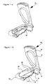
- Figure 1a is a partially cut-away perspective view of an embodiment of the opening member.
- Figure 1b shows the same embodiment as Figure 1a without the lever.
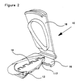
- Figure 2 is a partially cut-away perspective view of an alternative embodiment of the opening member, not showing the lever.
- FIG 3 is a detailed perspective view of the lever of the opening member of Figure 1.
- Figure 4 is a top plan view of the lever of Figure 3.
- Figure 5 is a top plan view of an alternative embodiment of a lever particularly useful for the opening member of Figure 2.
- Figure 6 is a top plan view of the laminate material of a container around the designated opening aperture.
- Figure 7 is a cross-sectional view of the laminate material along line 7-7 of Figure 6.
- Figure 8 is a top plan view of an alternative embodiment of the laminate material around the designated opening aperture.
- Figure 9 is a cross-sectional view of the laminate material along line 9-9 of Figure 8.
- FIG. 1 shows a preferred embodiment of the opening member (10).
- the opening member (10) comprises a flange (12) which forms a pouring aperture (14) and has a rim (16).
- the flange has a base (117) and an upper side (118).
- the upper side (118) of the flange (12) forms the upper end of the pouring aperture (14) through which liquids flow and exit the opening member (10) during use.
- the rim (16) extends outside the pouring aperture (14) from the base (117) of the flange (12).
- the rim (16) has a rectangular shape with rounded edges, however other shapes for the rim (16) like an oval shape or a shape following the outline of the flange (12) can also be used.
- the lower side of the rim (16) provides the contact area for joining the opening member (10) to a container.
- a preferred embodiment of the opening member (10) as shown in Figure 1 or 2 has a lid (18) which is hinged to the rim (16).
- the lid (18) could also be hinged to other parts of the opening member (10), for example the lid (18) could be directly hinged to flange (12).
- the lid (18) of Figure 1 further comprises a lip (19) which engages into the pouring aperture (14), thereby improving the tightness of the opening member (10) against spilling of liquid when the lid (18) is closed.
- the opening member (10) as shown in Figure 1 comprises a lever (20) which is cantilevered to the flange (12).
- the lever (20) as shown in a particular preferred embodiment in Figure 3 is of a key-hole shape and has a dimple (26) at the unsupported end.
- the lever (20) has a recess (22) or several recesses (22) as shown in Figures 3, 4 and 5.
- the lever is preferably joined to the flange in such a way that it provides indication of tampering or pilfering once it has been pushed in . This can be achieved for example by small material bridges between the lever (20) and the flange (12) which break upon initial use of the opening member (10).
- the opening member (10) preferably also has a pouring spout (24).
- the pouring spout (24) is preferably at the opposite end of the pouring aperture (14) from where the lid (18) is hinged to the opening member (10).
- pouring spouts (24) which provide not only direction to liquids coming through the pouring aperture (14) for pouring but which extend beyond the outer perimeter of the rim (16) to guide liquids clear of rim (16).
- pouring spouts (24) which are also angled such that liquid, which remains on the pouring spout (24), is drained back through the pouring aperture (14).
- the opening member has two flap doors (28) which extend inside the pouring aperture (14) and which are hinged on one side (29) to the flange (12).
- the flap doors (28) are disposed below the lever (20) such that upon initial opening the flap doors rotate in opposite direction around the hinged side (29) and engage into the recess (22) of the lever to provide a permanently open pouring aperture (14).
- the flap doors (28) extend inside the pouring aperture (14) in the same plane as the rim (16) and at the level of the base (117) of the flange (12).
- the opening member is made of plastic material.
- it is made of polyethylene, polypropylene, polystyrol or mixtures thereof. It can be produced by any manufacturing technique usual in the art. Preferably it is made by injection molding as a single piece.
- the present invention provides a reclosable liquid tight container comprising the opening member described above.
- the liquid tight containers of the present invention are made of laminate material.
- the laminate material comprises two barrier layers and a structural stability layer sandwiched between the barrier layers.
- the barrier layer forming the outside surface of the container, has the function of providing protection of the container against humidity and contamination from the container's environment. It preferably consists of one or several plies of plastic film, for example polyethylene, providing a liquid barrier and being weldable and compatible with many adhesives, particularly hotmelt adhesives.
- the barrier layer forming the inside surface of the container has the function of protecting and containing the liquid inside the container as well as protecting the structural stability layer from exposure to the liquid contents of the container.
- it also comprises one or several plies of plastic film, for example polyethylene.
- it may comprise a ply of gas tight material for example an aluminum foil which prevents in particular oxygen migrating into the container.
- the structural stability layer is sandwiched between the barrier layers together with any other additional layers which may be desired.
- the structural stability layer provides the laminate with the structural stability allowing to form self supporting containers with it.
- Most commonly used materials for the structural stability layer are paper or cardboard plys which themselves may be sandwiched together forming the structural stability layer.
- the laminate is formed in lamination processes well known in the art. Typically the two barrier layers and the structural stability layer are sandwiched together while applying high pressure and heat thereby forming an intimate bond between the layer interfaces. Bonding materials, if used at all, can be selected from a wide range of pressure sensitive, heat sensitive, hot melt type adhesives and other bonding agents.
- the container is made of laminate material. It preferably is made out of a single piece of laminate material which is cut and folded together so as to form either a gable top container or preferably a container resembling a parallelepiped.
- the important characteristic of the container is that it provides secure and hygienic containment for liquid products like non carbonated beverages.
- the container has an upper side which in the case of a gable top container is tilted and in case of a parallelepiped is a flat horizontal surface.
- the designated opening aperture (38) is located in the laminate material (30).
- the opening aperture (38) preferably consists of two parts which are hinged on one side (42) to the laminate material.
- Figure 7 and 9 a cross-sectional view taken along line 7-7 and 9-9 of Figure 6 and 8 respectively can be seen where the outer barrier layer (32), the structural stability layer (36) and the inner barrier layer (34) are indicated.
- the hinged side (42) between the designated opening aperture (38) the surrounding laminate material (30) is indicated as crease of the structural stability layer (36). This crease can be provided by simple compressing of the structural stability layer (36) alone, or of the whole laminate material (30) along the hinged side (42).
- the designated opening aperture (38) is formed by weakening the laminate material along the circumference of each part of the designated opening aperture (38) excluding the hinged side (42).
- the designated breaking contour which breaks upon initial opening of the container when pressing on the lever (20) and pushing-in the flap doors (28) of the opening member (10).
- the designated breaking contour as indicated in Figure 6 and 7 can be formed by straw-hole technology, that is by eliminating the structural stability layer (36) and laminating the two barrier layers (32,34) to each other through the removed structural stability layer (36).
- the designated breaking contour can also be formed as indicated in Figures 8 and 9 by partial cut technology. Partial cut technology simply provides cuts into the laminate (30) which do not extend through the full thickness of the laminate (30) and therefore maintain the integrity of the inner barrier layer (34).
- the flap door (28) of the opening member (10) is attached to the laminate material (30) in the area of the designated opening aperture (38) then there is no reason to keep the designated opening aperture (38) hinged on one side (42) to the surrounding laminate material. This is only done in order to prevent the laminate of the designated opening aperture (38) from falling inside the container. Therefore the designated breaking contour in case of an attachment between the flap door (28) and the laminate material (30) can be an endless line.
- the shape of the pouring aperture (14) and the designated opening aperture (38) is not limited to the shape shown in the drawings. Both apertures independently can be selected from round, oval, rectangular and triangular shapes or any other desired shape useful in providing the desired function.
- the opening aperture (38) has the same or a similar shape as the pouring aperture (14) of the opening member (10).
- a practical example would be the opening member (10) according to the embodiment shown in Figure 1 or 2 disposed on the laminate material (30) shown in Figure 6 or 8 such that the pouring aperture (14) of opening member (10) corresponds to the opening aperture (38) in the laminate material (30).
- a container according to the invention comprises the opening aperture (38) preferably at the edge of its upper side so that the pouring spout (24) reaches all the way to or even beyond the edge of the upper side of such a container.
- the lid (18) is preferably closed to protect the pouring aperture (14) for hygienic reasons as well as to provide the desired security against accidental opening of the opening aperture (38).
- the lid (18) is lifted and the lever (20) is pushed into the container thereby opening the flap doors (28) of the opening member (10)
- the flap doors (28) of the opening member (10) push-in the designated opening area (38).
- the flap doors (28) of the opening member engage in the recess (22) of the lever (20) and thereby are maintained permanently in an open position not obstructing the opening aperture (38) or the pouring aperture (14).
- the pouring aperture (14) can be reclosed by closing the lid (18) after initial opening.
Claims (10)
- Ein wiederverschließbarer Öffnungsbauteil (10), welcher umfaßt:a) einen Flansch (12), welcher eine Ausgußöffnung (14) bildet, wobei der genannte Flansch (12) an der Basis (117) einen Saum (16) aufweist, wobei der genannte Saum (16) sich über die genannte Ausgußöffnung (14) hinaus erstreckt;b) einen Deckel (18), um die genannte Ausgußöffnung (14) zu verschließen, wobei der genannte Deckel (18) am genannten Flansch (12) schwenkbar ist;c) einen Hebel (20), wobei der genannte Hebel (20) am genannten Flansch (12) einseitig eingespannt ist und in einer geschlossenen Position in die genannte Ausgußöffnung (14) unterhalb des genannten Deckels (18) paßt, und welcher an der Seite einen Fixierungsrücksprung (22) aufweist;wobei der genannte wiederverschließbare Öffnungsbauteil (10) dadurch gekennzeichnet ist, daß er weiters umfaßt:d) eine Klappentür (28), welche unterhalb des genannten Hebels (20) angeordnet ist und sich im Inneren der genannten Ausgußöffnung (14) erstreckt, wobei die genannte Klappentür (28) an einer Seite (29) am genannten Flansch (12) schwenkbar ist,wobei der Hebel (20) zum anfänglichen Öffnen durch Eindrücken der Klappentür (28) verwendet wird,
sodaß nach anfänglichem Öffnen durch Eindrücken der genannten Klappentür (28) er in den genannten Rücksprung (22) des genannten Hebels (20) eingreift, um eine permanent offene Ausgußöffnung (14) zu bilden. - Ein wiederverschließbarer Öffnungsbauteil (10) nach Anspruch 1, dadurch gekennzeichnet, daß er zwei Klappentüren (28) umfaßt, welche auf das Öffnen hin eine entgegengesetzte Drehrichtung aufweisen.
- Ein wiederverschließbarer Öffnungsbauteil (10) nach einem der vorhergehenden Ansprüche, dadurch gekennzeichnet, daß der genannte Öffnungsbauteil (10) weiters eine Ausgußtülle (24) umfaßt, wobei sich die genannte Ausgußtülle (24) vorzugsweise vom genannten Flansch (12) über den Rand des genannten Saums (16) hinaus erstreckt und sich in einem Winkel befindet, um die Flüssigkeit zurück in die genannte Ausgußöffnung (14) zu lenken.
- Ein wiederverschließbarer Öffnungsbauteil (10) nach einem der vorhergehenden Ansprüche, dadurch gekennzeichnet, daß der genannte Hebel (20) die Form eines Schlüsselloches mit einer Vertiefung (26) am freien Ende des genannten Hebels (20) aufweist.
- Ein wiederverschließbarer Öffnungsbauteil (10) nach einem der vorhergehenden Ansprüche, dadurch gekennzeichnet, daß der genannte Öffnungsbauteil (10) aus Polyethylen, Polypropylen, Polystyrol oder Mischungen derselben hergestellt ist.
- Ein wiederverschließbarer flüssigkeitsdichter Behälter, wlecher eine Oberseite aufweist und aus einem Laminatmaterial (30) hergestellt ist, wobei der genannte Behälter an der genannten Oberseite eine bezeichnete Öffnungsausnehmung (38) umfaßt, dadurch gekennzeichnet, daß er weiters einen der Öffnungsbauteile (10) der Ansprüche 1 bis 5 umfaßt, und dadurch, daß der genannte Bauteil (10) angeordnet ist, um der genannten Öffnungsausnehmung (38) zu entsprechen, und mit der Außenseite des genannten Behälters durch eine endlose flüssigkeitsdichte Dichtung entlang dem genannten Saum (16) verbunden ist.
- Ein wiederverschließbarer flüssigkeitsdichter Behälter nach Anspruch 6, dadurch gekennzeichnet, daß der genannte Behälter ein Quader ist.
- Ein wiederverschließbarer flüssigkeitsdichter Behälter nach Anspruch 6 oder 7, dadurch gekennzeichnet, daß die genannte endlose flüssigkeitsdichte Dichtung durch Aufschmelzklebstoff oder Schweißen beigestellt ist.
- Ein wiederverschließbarer flüssigkeitsdichter Behälter nach Anspruch 6 - 8, dadurch gekennzeichnet, daß das genannte Laminatmaterial (30) eine äußere und eine innere Flüssigkeitssperrschichte (32, 34) um eine strukturelle Stabilitätsschichte (36) herum aufweist, wobei die genannte strukturelle Stabilitätsschichte (36) vorzugsweise Papier, Karton oder Kombinationen derselben umfaßt.
- Ein wiederverschließbarer flüssigkeitsdichter Behälter nach Anspruch 9, dadurch gekennzeichnet, daß die genannte äußere Sperrschichte (32) und die genannte innere Sperrschichte (34) eine Polyethylenschichte umfassen, wobei die genannte innere Sperrschichte (34) vorzugsweise weiters eine gasdichte Schichte umfaßt.
Priority Applications (6)
| Application Number | Priority Date | Filing Date | Title |
|---|---|---|---|
| ES92111411T ES2082283T3 (es) | 1992-07-06 | 1992-07-06 | Miembro de apertura de cierre repetible de una sola pieza para recipiente de envase de liquido. |
| DK92111411.2T DK0577866T3 (da) | 1992-07-06 | 1992-07-06 | Element til aseptiske væskeemballeringsbeholdere med genlukkelig åbning |
| AT92111411T ATE133385T1 (de) | 1992-07-06 | 1992-07-06 | Wiederverschliessbares öffnungselement aus einem stück für flüssigkeitsverpackungen |
| EP92111411A EP0577866B1 (de) | 1992-07-06 | 1992-07-06 | Wiederverschliessbares Öffnungselement aus einem Stück für Flüssigkeitsverpackungen |
| DE69207896T DE69207896T2 (de) | 1992-07-06 | 1992-07-06 | Wiederverschliessbares Öffnungselement aus einem Stück für Flüssigkeitsverpackungen |
| GR960400023T GR3018789T3 (en) | 1992-07-06 | 1996-01-25 | Single piece reclosable opening member for liquid packaging container |
Applications Claiming Priority (1)
| Application Number | Priority Date | Filing Date | Title |
|---|---|---|---|
| EP92111411A EP0577866B1 (de) | 1992-07-06 | 1992-07-06 | Wiederverschliessbares Öffnungselement aus einem Stück für Flüssigkeitsverpackungen |
Publications (2)
| Publication Number | Publication Date |
|---|---|
| EP0577866A1 EP0577866A1 (de) | 1994-01-12 |
| EP0577866B1 true EP0577866B1 (de) | 1996-01-24 |
Family
ID=8209785
Family Applications (1)
| Application Number | Title | Priority Date | Filing Date |
|---|---|---|---|
| EP92111411A Expired - Lifetime EP0577866B1 (de) | 1992-07-06 | 1992-07-06 | Wiederverschliessbares Öffnungselement aus einem Stück für Flüssigkeitsverpackungen |
Country Status (6)
| Country | Link |
|---|---|
| EP (1) | EP0577866B1 (de) |
| AT (1) | ATE133385T1 (de) |
| DE (1) | DE69207896T2 (de) |
| DK (1) | DK0577866T3 (de) |
| ES (1) | ES2082283T3 (de) |
| GR (1) | GR3018789T3 (de) |
Families Citing this family (3)
| Publication number | Priority date | Publication date | Assignee | Title |
|---|---|---|---|---|
| DE4409946A1 (de) * | 1994-03-23 | 1995-09-28 | Pkl Verpackungssysteme Gmbh | Quaderförmige Flachgiebelverbundpackung und Verfahren zu ihrer Herstellung |
| US9004344B2 (en) | 2009-07-30 | 2015-04-14 | Meadwestvaco Corporation | Paperboard security packages |
| EP2889231A1 (de) * | 2013-12-30 | 2015-07-01 | Tetra Laval Holdings & Finance SA | Verpackungsmaterial und Verpackungsbehälter mit einer Öffnungsvorrichtung daraus |
Family Cites Families (3)
| Publication number | Priority date | Publication date | Assignee | Title |
|---|---|---|---|---|
| DE2659275C3 (de) * | 1976-12-29 | 1980-10-09 | Papier- Und Kunststoff-Werke Linnich Gmbh, 4000 Duesseldorf | Behälter für Flüssigkeiten mit einem einstechbaren Ausgießer |
| US4934590A (en) * | 1989-02-27 | 1990-06-19 | Combibloc, Inc. | Package closure |
| WO1992000884A1 (en) * | 1990-07-10 | 1992-01-23 | Combibloc, Inc. | Package closure and package preparation |
-
1992
- 1992-07-06 ES ES92111411T patent/ES2082283T3/es not_active Expired - Lifetime
- 1992-07-06 EP EP92111411A patent/EP0577866B1/de not_active Expired - Lifetime
- 1992-07-06 AT AT92111411T patent/ATE133385T1/de active
- 1992-07-06 DK DK92111411.2T patent/DK0577866T3/da active
- 1992-07-06 DE DE69207896T patent/DE69207896T2/de not_active Expired - Fee Related
-
1996
- 1996-01-25 GR GR960400023T patent/GR3018789T3/el unknown
Also Published As
| Publication number | Publication date |
|---|---|
| DE69207896D1 (de) | 1996-03-07 |
| EP0577866A1 (de) | 1994-01-12 |
| DE69207896T2 (de) | 1996-09-05 |
| ATE133385T1 (de) | 1996-02-15 |
| GR3018789T3 (en) | 1996-04-30 |
| DK0577866T3 (da) | 1996-05-20 |
| ES2082283T3 (es) | 1996-03-16 |
Similar Documents
| Publication | Publication Date | Title |
|---|---|---|
| US4770325A (en) | Pour spout for containers | |
| US4948015A (en) | Carton equipped with liquid pouring-out device | |
| RU2188784C2 (ru) | Повторно-закрываемое открывающее устройство для упаковок для текучих пищевых продуктов | |
| US6364164B1 (en) | Device for opening packages of pourable food products | |
| US4705197A (en) | Pour spout for containers | |
| EP0238947B1 (de) | Verpackungsbehälter, versehen mit einer wiederverschliessbaren Öffnungsanordnung | |
| US4699290A (en) | Sanitary tamperproof double closure container end cap | |
| KR100523090B1 (ko) | 재밀폐 가능한 주출 요소 및 그것을 구비한 평평한 박공 지붕 형태의 복합 재료 포장재 | |
| US5009364A (en) | Easy-open package for fluent material | |
| EP0580593A1 (de) | Behälterverschluss und behälter. | |
| US4433808A (en) | Pourable, recloseable lid | |
| CZ286830B6 (en) | Prismatic wrapper with roof-like wall folded in flat formation and process for producing thereof | |
| EP0577865B1 (de) | Aseptische Flüssigkeitsverpackung versehen mit einem wiederverschliessbaren Öffnungselement | |
| EP0312816B1 (de) | Ausguss für Flüssigkeitsbehälter | |
| AU718330B2 (en) | Device for the opening and reclosing of containers | |
| EP0577867B1 (de) | Aseptische Flüssigkeitsverpackung, versehen mit einem wiederverschliessbaren Öffnungselement | |
| AU2001279734B2 (en) | Opening device for packaging containers | |
| EP0577866B1 (de) | Wiederverschliessbares Öffnungselement aus einem Stück für Flüssigkeitsverpackungen | |
| CA2706447A1 (en) | Cylindrical spout for disposable cartons | |
| US5007542A (en) | Recloseable carton with pouring spout | |
| EP0141229A1 (de) | Wiederverschliessbare sterile Verpackung | |
| US5228616A (en) | Package container provided with a strip-type opening arrangement | |
| EP0471274B1 (de) | Verpackungsbehälter mit einer streifenförmigen Öffnungsvorrichtung | |
| CA1189462A (en) | Packing container | |
| JP3043515B2 (ja) | ブリック型紙容器 |
Legal Events
| Date | Code | Title | Description |
|---|---|---|---|
| PUAI | Public reference made under article 153(3) epc to a published international application that has entered the european phase |
Free format text: ORIGINAL CODE: 0009012 |
|
| AK | Designated contracting states |
Kind code of ref document: A1 Designated state(s): AT BE CH DE DK ES FR GB GR IT LI LU NL PT SE |
|
| 17P | Request for examination filed |
Effective date: 19940613 |
|
| 17Q | First examination report despatched |
Effective date: 19940718 |
|
| GRAA | (expected) grant |
Free format text: ORIGINAL CODE: 0009210 |
|
| AK | Designated contracting states |
Kind code of ref document: B1 Designated state(s): AT BE CH DE DK ES FR GB GR IT LI LU NL PT SE |
|
| REF | Corresponds to: |
Ref document number: 133385 Country of ref document: AT Date of ref document: 19960215 Kind code of ref document: T |
|
| REF | Corresponds to: |
Ref document number: 69207896 Country of ref document: DE Date of ref document: 19960307 |
|
| ET | Fr: translation filed | ||
| REG | Reference to a national code |
Ref country code: CH Ref legal event code: NV Representative=s name: RITSCHER & SEIFERT PATENTANWAELTE VSP |
|
| REG | Reference to a national code |
Ref country code: ES Ref legal event code: FG2A Ref document number: 2082283 Country of ref document: ES Kind code of ref document: T3 |
|
| REG | Reference to a national code |
Ref country code: GR Ref legal event code: FG4A Free format text: 3018789 |
|
| ITF | It: translation for a ep patent filed |
Owner name: ING. C. GREGORJ S.P.A. |
|
| REG | Reference to a national code |
Ref country code: DK Ref legal event code: T3 |
|
| PGFP | Annual fee paid to national office [announced via postgrant information from national office to epo] |
Ref country code: GB Payment date: 19960627 Year of fee payment: 5 |
|
| PGFP | Annual fee paid to national office [announced via postgrant information from national office to epo] |
Ref country code: LU Payment date: 19960701 Year of fee payment: 5 |
|
| PGFP | Annual fee paid to national office [announced via postgrant information from national office to epo] |
Ref country code: FR Payment date: 19960709 Year of fee payment: 5 Ref country code: DK Payment date: 19960709 Year of fee payment: 5 |
|
| PGFP | Annual fee paid to national office [announced via postgrant information from national office to epo] |
Ref country code: AT Payment date: 19960711 Year of fee payment: 5 |
|
| PGFP | Annual fee paid to national office [announced via postgrant information from national office to epo] |
Ref country code: DE Payment date: 19960712 Year of fee payment: 5 |
|
| PGFP | Annual fee paid to national office [announced via postgrant information from national office to epo] |
Ref country code: SE Payment date: 19960717 Year of fee payment: 5 |
|
| PGFP | Annual fee paid to national office [announced via postgrant information from national office to epo] |
Ref country code: CH Payment date: 19960722 Year of fee payment: 5 |
|
| PGFP | Annual fee paid to national office [announced via postgrant information from national office to epo] |
Ref country code: PT Payment date: 19960729 Year of fee payment: 5 Ref country code: NL Payment date: 19960729 Year of fee payment: 5 Ref country code: ES Payment date: 19960729 Year of fee payment: 5 |
|
| PGFP | Annual fee paid to national office [announced via postgrant information from national office to epo] |
Ref country code: GR Payment date: 19960731 Year of fee payment: 5 |
|
| SC4A | Pt: translation is available |
Free format text: 960411 AVAILABILITY OF NATIONAL TRANSLATION |
|
| PGFP | Annual fee paid to national office [announced via postgrant information from national office to epo] |
Ref country code: BE Payment date: 19960828 Year of fee payment: 5 |
|
| PLBE | No opposition filed within time limit |
Free format text: ORIGINAL CODE: 0009261 |
|
| STAA | Information on the status of an ep patent application or granted ep patent |
Free format text: STATUS: NO OPPOSITION FILED WITHIN TIME LIMIT |
|
| 26N | No opposition filed | ||
| PG25 | Lapsed in a contracting state [announced via postgrant information from national office to epo] |
Ref country code: LU Free format text: LAPSE BECAUSE OF NON-PAYMENT OF DUE FEES Effective date: 19970706 Ref country code: GB Free format text: LAPSE BECAUSE OF NON-PAYMENT OF DUE FEES Effective date: 19970706 Ref country code: DK Free format text: LAPSE BECAUSE OF NON-PAYMENT OF DUE FEES Effective date: 19970706 Ref country code: AT Free format text: LAPSE BECAUSE OF NON-PAYMENT OF DUE FEES Effective date: 19970706 |
|
| REG | Reference to a national code |
Ref country code: DK Ref legal event code: EBP |
|
| PG25 | Lapsed in a contracting state [announced via postgrant information from national office to epo] |
Ref country code: SE Effective date: 19970707 Ref country code: ES Free format text: LAPSE BECAUSE OF THE APPLICANT RENOUNCES Effective date: 19970707 |
|
| PG25 | Lapsed in a contracting state [announced via postgrant information from national office to epo] |
Ref country code: LI Free format text: LAPSE BECAUSE OF NON-PAYMENT OF DUE FEES Effective date: 19970731 Ref country code: GR Free format text: LAPSE BECAUSE OF NON-PAYMENT OF DUE FEES Effective date: 19970731 Ref country code: CH Free format text: LAPSE BECAUSE OF NON-PAYMENT OF DUE FEES Effective date: 19970731 Ref country code: BE Free format text: LAPSE BECAUSE OF NON-PAYMENT OF DUE FEES Effective date: 19970731 |
|
| BERE | Be: lapsed |
Owner name: THE PROCTER & GAMBLE CY Effective date: 19970731 |
|
| PG25 | Lapsed in a contracting state [announced via postgrant information from national office to epo] |
Ref country code: PT Free format text: LAPSE BECAUSE OF NON-PAYMENT OF DUE FEES Effective date: 19980131 |
|
| PG25 | Lapsed in a contracting state [announced via postgrant information from national office to epo] |
Ref country code: NL Free format text: LAPSE BECAUSE OF NON-PAYMENT OF DUE FEES Effective date: 19980201 |
|
| GBPC | Gb: european patent ceased through non-payment of renewal fee |
Effective date: 19970706 |
|
| REG | Reference to a national code |
Ref country code: CH Ref legal event code: PL |
|
| PG25 | Lapsed in a contracting state [announced via postgrant information from national office to epo] |
Ref country code: FR Free format text: LAPSE BECAUSE OF NON-PAYMENT OF DUE FEES Effective date: 19980331 |
|
| NLV4 | Nl: lapsed or anulled due to non-payment of the annual fee |
Effective date: 19980201 |
|
| PG25 | Lapsed in a contracting state [announced via postgrant information from national office to epo] |
Ref country code: DE Free format text: LAPSE BECAUSE OF NON-PAYMENT OF DUE FEES Effective date: 19980401 |
|
| EUG | Se: european patent has lapsed |
Ref document number: 92111411.2 |
|
| REG | Reference to a national code |
Ref country code: FR Ref legal event code: ST Ref country code: PT Ref legal event code: MM4A Free format text: LAPSE DUE TO NON-PAYMENT OF FEES Effective date: 19980131 |
|
| REG | Reference to a national code |
Ref country code: ES Ref legal event code: FD2A Effective date: 20001102 |
|
| PG25 | Lapsed in a contracting state [announced via postgrant information from national office to epo] |
Ref country code: IT Free format text: LAPSE BECAUSE OF NON-PAYMENT OF DUE FEES;WARNING: LAPSES OF ITALIAN PATENTS WITH EFFECTIVE DATE BEFORE 2007 MAY HAVE OCCURRED AT ANY TIME BEFORE 2007. THE CORRECT EFFECTIVE DATE MAY BE DIFFERENT FROM THE ONE RECORDED. Effective date: 20050706 |