EP0577787B1 - Abnehmbare endocardiale leitung - Google Patents
Abnehmbare endocardiale leitung Download PDFInfo
- Publication number
- EP0577787B1 EP0577787B1 EP93900608A EP93900608A EP0577787B1 EP 0577787 B1 EP0577787 B1 EP 0577787B1 EP 93900608 A EP93900608 A EP 93900608A EP 93900608 A EP93900608 A EP 93900608A EP 0577787 B1 EP0577787 B1 EP 0577787B1
- Authority
- EP
- European Patent Office
- Prior art keywords
- lead
- sheath
- conductor
- proximal
- distal
- Prior art date
- Legal status (The legal status is an assumption and is not a legal conclusion. Google has not performed a legal analysis and makes no representation as to the accuracy of the status listed.)
- Expired - Lifetime
Links
Images



Classifications
-
- A—HUMAN NECESSITIES
- A61—MEDICAL OR VETERINARY SCIENCE; HYGIENE
- A61N—ELECTROTHERAPY; MAGNETOTHERAPY; RADIATION THERAPY; ULTRASOUND THERAPY
- A61N1/00—Electrotherapy; Circuits therefor
- A61N1/02—Details
- A61N1/04—Electrodes
- A61N1/05—Electrodes for implantation or insertion into the body, e.g. heart electrode
- A61N1/056—Transvascular endocardial electrode systems
Definitions
- This invention relates to coiled wire medical lead structures, such as transvenous, endocardial cardiac pacemaker and/or cardioverter/defibrillator leads. More particularly this invention relates to an improved structure for strengthening such leads to enable their intact removal by forceful traction after a period of chronic implant, specifically without the need of special lead removal devices.
- transvenous pacing and cardioversion/defibrillation leads have been developed for endocardial introduction into different chambers of a patient's heart, typically the right ventricle or right atrial appendage, as well as the coronary sinus.
- These flexible leads usually are constructed having an outer polymeric sheath encasing one or more electrical, coiled wire conductors.
- One coiled wire conductor is typically attached at its distal tip to the shank portion of a tip electrode.
- one or more further coiled wire conductors are provided in coaxial or co-linear relation to the first coiled wire conductor and are connected at its distal end to more proximally located, ring-shaped electrodes situated along the lead body.
- the proximal ends of each conductor are coupled to a connector which includes a single pin in unipolar leads and additional pins or in-line rings in bipolar and multi-polar leads.
- the tip electrode is usually placed in contact with myocardial tissue by passage through a venous access, often the subclavian vein or one of its tributaries, which leads to the endocardial surface of the heart chambers.
- the tip electrode is held in place passively by trabeculations of myocardial tissue or actively through the use of an actively manipulated anchor or screw that penetrates the myocardium as described in U.S. Patent Nos. 4,209,019 and 3,974,834, assigned to Medtronic, Inc.
- the distal ends of many available leads include flexible tines, flanges, or finger-like projections which extend radially outward and usually are molded from and are integral with the distal portion of the insulating sheath of the lead, usually proximal to the tip electrode and distal from any ring electrodes.
- These passive fixation mechanisms allow surrounding growth of tissue and scar in chronically implanted leads to fix the electrode tip in position in the heart and prevent dislodgement of the tip during the life of the lead.
- a blood clot forms about the fixation mechanism and insulating sheath (due to enzymes released as a result of irritation of the trabeculations of the myocardial tissue by the presence of the electrode tip) until scar tissue eventually forms, usually in three to six weeks. Until scar tissue develops, the fixation mechanisms described above prevent early dislodgement of the lead tip.
- endocardial leads nevertheless occasionally fail for a variety of reasons such as the following: insulation failure; sensor failure; coiled wire conductor fracture; and an increase in electrode resistance beyond a desirable level. Also, in some instances, it may be desirable to electronically stimulate different portions of the heart than are presently being stimulated with leads already in place. There are a considerable number of patients who have had one or more, and sometimes as many as four or five previously and currently used leads in their veins and heart.
- the risks of leaving unusable leads in the heart and venous path include the following: an increased likelihood of infection; a potentially fatal complication which may necessitate removal of the lead; obstruction to blood flow as in "SVC syndrome"; and an increased likelihood of the formation of blood clots which may embolize to the lung and produce severe complications and even death.
- extra leads in the heart can interfere with cardiac valve and mechanical function. Thus, it is desirable to remove old unusable leads.
- the presence of unused leads in the venous pathway and inside the heart can cause considerable difficulty in the positioning and attachment of new endocardial leads in the heart.
- Grasping and applying traction on the proximal ends of the chronically implanted leads results in directing pulling forces substantially along the length of the lead. These pulling forces are transmitted through the lead to its distal tip. Because of the fibrosis enveloping the electrode, substantial resistance to the pulling forces is experienced, and stress is placed on the lead as well as the heart.
- endocardial lead construction typically includes a polymeric insulating sheath, within which one or more electrical, coiled wire conductors are mounted and attached to distally located electrodes and proximally located connector pins.
- these leads have typically been constructed in such a manner which tends to make their subsequent removal difficult.
- When subjected to pulling forces along its length, such a lead usually disassembles.
- the polymeric insulating sheath can break away from the proximal and distal ends of the lead while the coiled wire conductor is stretched until it breaks or has to be cut off at the venous access site.
- the exposed end of a coiled wire conductor, once extended and stretched, may present the risk of cutting adjacent tissue if left in place. In such cases, only open heart surgery can fully remove the lead.
- a further complication of applying direct manual pulling force to the proximal end of the lead is the avulsion of the heart, which can induce arrhythmias or even lead to death.
- care must be taken to observe the procedure under fluoroscopy and to avoid either breaking the lead structure or causing avulsion of the heart.
- an elongated electrical medical lead for use with a pulse generator to be implanted within a human body, said lead having a proximal and distal lead end and further comprising: an outer insulating sheath having a relaxed predetermined sheath length between a proximal and distal sheath end thereof, said sheath being capable of lengthening under tension; at least one conductor positioned within said outer insulating sheath and extending between said proximal and distal sheath ends thereof, each of said at least one conductor having a relaxed predetermined conductor length between a proximal and distal conductor end thereof, and each of said at least one conductor being capable of lengthening under tension; a connector interconnecting said proximal sheath end with said proximal conductor end of each of said at least one conductor therein, said connector for providing an electrical connection to said implanted pulse generator; at least one tip electrode disposed adjacent said distal sheath end of said lead,
- EP-A-0369044 discloses a bipolar medical lead having an electrical conductor in the form of a braided hose. Part of the hose is exposed to function as the neutral electrode.
- the improvement in the lead body construction comprises one or more normally relaxed, nonextensible filaments loosely contained with the insulating sheath and having proximal and distal ends mechanically coupled to the connector and the normally insulated portion of the electrode, respectively, for restraining the stretching of the lead body to a stretched length exceeding the relaxed predetermined length by an amount sufficient to allow the lead to be stretched without breaking in its normal usage and during removal by traction.
- the filament(s) preferably take the form of Dacron® polyester yarn or cord having a size of approximately 2,600 denier that are mechanically attached to the connector and the electrode shank by passing the ends of the filament through holes therein and tying the ends off and either wound loosely about a coiled wire conductor or extended through the lumen of the coiled wire conductor.
- the filaments may be replaced by a loosely woven fabric sheath formed in a tubular shape and fitted in the space between the outer sheath and the coiled wire conductor or between the outer sheath and the inner sheath surrounding one of the coiled wire conductors.
- the ends of the sheath are mechanically attached to the connector and the electrode assembly such that as the loosely woven fibers are stretched, they tighten against a sheath surrounding the conductor or the conductor itself, and thus grip the insulation or the coiled wire conductor through the length of the lead body, substantially increasing its tensile pull strength.
- the filament(s) or woven sheath may be embedded within or on the interior surface of the outer insulating sheath on an inner insulating sheath of a bipolar or multipolar lead.
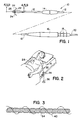
- FIG. 1 shows a side plan view of a simple, unipolar, endocardial pacing lead according to the present invention.
- the lead is provided with an elongated lead body 10 which is covered with an insulation sheath 12, which may be fabricated of silicone rubber, polyurethane or other suitable plastic.
- an insulation sheath 12 which may be fabricated of silicone rubber, polyurethane or other suitable plastic.
- connector assembly 16 At the proximal end of lead body 10 is connector assembly 16, which is provided with sealing rings 18 and which carries connector pin 20.
- Connector assembly 16 may be constructed using techniques known to the art, and may be fabricated of silicone rubber, polyurethane or other suitable plastic.
- Connector pin 20 may be fabricated of stainless steel or other conductive material.
- electrode 26 At the distal end of lead body 10 is discussed in more detail below.
- Tines 24 engage with heart tissue and urge electrode 26 into contact with the endocardium, in a direction parallel to the lead axis.
- Tines 24 are more fully described in U.S. Patent No. 3,902,501, issued to Citron et al. Slidably mounted around the site of venous insertion.
- Sleeve 14 is more fully described in commonly assigned U.S. Patent No. 4,437,475.
- FIG. 2 a cardiac pacing lead, generally designated as 10 in FIG. 1, is illustrated such that its implanted electrode 26 is fixed at its most distal tip by tissue and/or trabeculae in the right ventricle of the illustrated heart 28 of the reclining patient.
- the implanted condition generally illustrated in the drawing includes having a substantial length of the cardiac pacing lead 10 implanted within an appropriate vein (not shown) of the patient, while the proximal connector pin 20 of the lead 10 is accessible for connection to a pacemaker in accordance with generally well-known structures and procedures.
- steady traction is employed in the manner shown in FIG. 2.
- the proximal connector 16 and connector pin 20 of the lead 10 is exposed by an incision and attached to a line 32.
- the line 32 is suspended over a shoulder level pulley 34 and attached to a weight 36, e.g., 0,450 to 4,5 kg (1 to 10 lbs).
- a weight 36 e.g., 0,450 to 4,5 kg (1 to 10 lbs).
- the lead body is strengthened by the inclusion of one or more slack filaments 40 within the insulating sheath 12 of the lead depicted in FIGS. 1 and 2 and wound loosely about the coil 54 of at least one of the coiled wire conductors in either a unipolar embodiment as depicted in FIG. 1 or in bipolar and multipolar embodiments thereof.
- slack filaments 40 within the insulating sheath 12 of the lead depicted in FIGS. 1 and 2 and wound loosely about the coil 54 of at least one of the coiled wire conductors in either a unipolar embodiment as depicted in FIG. 1 or in bipolar and multipolar embodiments thereof.
- the slack, loosely wound, filament 40 is shown in a partial schematic view of its orientation to the coiled wire conductor 54 merely to illustrate that the filament or filaments are intentionally loosely wound around either the inner or outer coiled wire conductor to allow the lead to possess its normal flexibility and springiness in its normal intended usage in the implantation depicted, for example, in FIG. 2.
- the filament 40 extends between the connector 16 at the proximal end of the lead 10 and the tip electrode 26 at the distal end of the lead depicted in FIG. 1 and within the insulating sheath 12.
- the filament draws tight against the coiled wire conductors and prevents further stretching of the lead body, unless it is subjected to a pulling force far in excess of most manual traction situations, such as more than 9-13,5 kg (20-30 lbs.) of axially applied force.
- filaments 40 are lengths of Dacron woven yarn of relatively small cross-sectional area.
- a yarn, as opposed to a monofilament, is preferred that possesses the requisite strength, will flatten out in a constrained space and is not susceptible to stretching, but will instead break at the desired 20 lbs. traction applied to the lead body.
- FIGS. 4 and 5 alternative attachment mechanisms are depicted for attaching one or more filaments 40 to the shank 46 of the distal electrode 26.
- the distal electrode 26 preferably takes the form of that electrode shown in U.S. Patent No. 4,502,492.
- FIG. 4 shows a cross-sectional view of the distal end of the lead of FIG. 1.
- electrode 26 is seen to be provided with an elongated, proximally extending tubular shank 46 which has a central lumen 56.
- swaging pin 48 Mounted within lumen 56 are swaging pin 48 and coiled conductor 54.
- Crimps 50 maintain coiled conductor 54 tightly fixed between swaging pin 48 and tubular portion 46 of electrode 26.
- This structure provides mechanical and electrical coupling of conductor 54 to electrode 26.
- Coiled conductor 54 extends proximally within insulating sheath 12 to the proximal end of the lead and is coupled to connector pin 20 (FIG. 1).
- Swaging pin 48 is provided with a central lumen 52 into which a stylet may be inserted.
- Coiled conductor 54 may be fabricated of MP35N alloy or other suitable conductive material, and is preferably a multifilar coil as shown in FIG. 3.
- Swaging pin 48 may be fabricated of stainless steel or other appropriate metal.
- Electrode 26 is preferably constructed of or provided with a coating of platinum or of a platinum alloy, but may also be constructed of titanium, rhodium, iridium, or alloys thereof.
- the distal end of the lead of FIGS. 1 and 2 as described in the aforementioned '492 patent is modified as depicted in FIG. 4 to provide a hole 45 through the tubular shank portion 46 extending between recesses 47, 49 distal to the crimps 50.
- the filament ends 42, 43 of filaments 40, 41 are threaded in opposite directions through hole 45 and tied off and fitted within the recesses 47 and 49 of the tubular portion 46.
- the recesses 47, 49 and hole 45 may or may not be filled with epoxy cement to stabilize the filaments 40, 41 in hole 45 and recesses 47 and 49.
- the filaments 40, 41 extend along the outer surface of the tubular shank portion 46 and within the tine sheath 22 and through grooves cut in the shank ridge at 51, 53 whereafter it is wound loosely about the coil 54 as shown in FIG. 3 through the length of the lead body.
- a single filament could be employed in the same fashion as shown in the partial cross-sectional view of FIG. 4.
- FIG. 5 a further embodiment of the connection of the distal end of the filament with the shank of the connector end is depicted.
- the filament 40 extends through the lumen 55 of the coiled wire conductor 54 throughout its length and through the lumen 52 of the swaging pin 48.
- the filament is threaded through the lumen 52 and knotted at its distal end 42.
- a dab of epoxy may be applied to the knot 42.
- the coiled wire conductor 54 is slipped over the outer surface of the swaging pin 48, and the assembly is inserted into the central lumen 56 of the elongated shank tubular portion 46 to locate the knot 42 in the end 57 of lumen 56.
- the mechanical and electrical attachment is completed in the manner described above by swaging at points 50.
- the filament extends loosely down the lumen of the coiled wire conductor to the connector where it is attached thereto.
- FIGS. 6 and 7 the connector end of the lead of FIGS. 1 and 2 is depicted in partial cross-section to illustrate the fashion in which the proximal end of the filaments 40, 41 may be attached thereto.
- FIG. 6 is a modification of FIG. 2 of U.S. Patent No. 4,944,088 incorporated herein by reference in its entirety.
- the filaments 40, 41 actually constitute a single length of filament which are passed through holes 100, 102, in a ring element 144 and wound about the inner coil 134 or sheath 114 to extend between the coil 134 and the inner sheath 114 or the outer sheath 128 through the length of the lead body.
- the filaments 40, 41 may be loosely wound about either the inner sheath or coil and connected at the distal tip electrode in the fashion depicted, e.g., in FIG. 4 as described above. It will be understood that the filaments 40, 41 could be threaded through a similar connection in a unipolar connector and with or without the inner sheath 114.
- FIG. 6 shows a cross-sectional view of the proximal portion of a bipolar connector assembly showing the interconnection of the multiconductor coil 134 with the other components of the connector assembly.
- Multiconductor coil 134 includes a first coil conductor coupled to connector pin 124 and a second coil conductor electrically coupled to ring member 122.
- the connector assembly is fabricated by first laser welding ring member 122 to cylindrical member 136 by means of a circumferential laser weld at 138 to form a connector ring assembly. Assembled ring member 122 and cylindrical member 136 are assembled over connector pin 124, placed into a mold, and insulative sleeve 126 is then injection molded between them. This process is disclosed in more detail in Hess U.S. Patent No. 4,572,605.
- connector pin 124 The complete assembly of connector pin 124, insulative sleeve 126, ring member 122 and tubular member 136 is then coupled to one conductor 140 of multiconductor coil 134.
- Conductor 140 is screwed onto the distal end of connector pin 124, with protrusion 142 acting as a screw thread.
- Conductor 140 is screwed onto connector pin 124 until its proximal end abuts against circular flange 144.
- Conductor 140 is then coupled to circular flange 144 at 146 by means of a spot laser weld.
- the spacing of intermediate circular flange 144 and protrusion 142 allows for a limited amount of strain relief immediately distal to the spot laser weld at 146.
- Tubular extension 148 which takes the form of a cylinder having an extended longitudinal slot 150 is then slid over the distal end of cylindrical member 136 and coupled to it by means of a circumferential laser weld at 153.
- a shallow grooved section 152 having a groove that corresponds generally to the size of conductor 154, is located at the proximal end of slot 150 in tubular extension 148.
- Conductor 154 is stripped of insulation and laid lengthwise in the grooved area 152, and laser welded to extension 148.
- insulative sleeve 128 is slid over extension 148 and over cylindrical member 136.
- Member 136 is provided with a cross bore 156, which may be filled with medical adhesive, thereby bonding insulative sleeve 128 to insulative sleeve 126.
- the entire assembly is backfilled with adhesive injected between insulative sheath 114 and insulative sleeve 128, filling the area between insulative sleeve 128 and sheath 114, as well as the lumen 158 of sleeve 128 and the lumen 160 of tubular extension 148.
- This serves to bond the components of the connector assembly to one another and to insulative sleeve 128 and to electrically insulate the conductor 140 and connector pin 124 from the conductor 154.
- the backfilled adhesive is not shown in this illustration.
- Mounted within multiconductor coil 134 is a Teflon® plastic liner 162, which serves as a passageway for a stylet.
- the internal lumen of liner 62 is aligned with the internal bore 164 of connector pin 124.
- the filaments 40, 41 in this embodiment actually comprise a single filament threaded through holes 100, 102 shown in the cross-sectional view of FIG. 7 extending through the circular flange 144 in and out of holes 100 and 102. It will be appreciated that a single filament could be passed through the holes 100, 102 and tied off, rather than looped back as the second filament as shown in FIG. 6. It will also be appreciated that the filament or filaments may be looped through holes in other parts of the proximal lead assembly of FIG. 6, such as holes passing through the sidewalls of tubular extension 148.
- the connector end as described above in conjunction with FIGS. 6 and 7 involves the implementation of the invention in the context of the above '088 patent where the individual conductors of multiconductor coil 134 are separately insulated and connected to connector pin 124 and ring 122. It will be understood that the same attachment of the filaments 40, 41 through the flange 144 may be accomplished in less complex connectors where all of the multifilar, coaxial conductors are electrically and mechanically connected to the connector pin 124 and the tubular extension 148 and its attachment to one of the conductors of coil 134 is eliminated. In such embodiments, the flange 144 is present and functions as described above, but it may have a larger relative diameter than illustrated in FIG. 6.
- the proximal end of the filament 40 would be drawn through a spaced apart turn of the multifilar coil 134 at its juncture with the distal end of the connector pin 124 and attached in the same fashion as depicted in FIGS. 6 and 7 and described above.
- Other mechanisms for attaching the proximal and distal ends of the filament will be apparent to those of skill in the art and depend upon particular attachment configurations of existing and future lead designs.
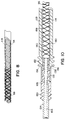
- FIG. 8 it depicts in partial side elevation view, the arrangement of a loosely wound, coaxial, tubular reinforcing sheath 66 fitted over the coiled wire conductor 54 or the insulating sheath 114.
- the loosely wound tubular sheath is an extension of the number of filaments from one or two as previously described but would employ a Dacron fabric having individual webs of a greater width than thickness and which would be capable of being stretched a certain amount until its shrinking inner diameter would firmly grip the outer surface of the coiled wire conductor 54 or the insulating sheath 114.
- the reinforcing sheath 66 would operate in the fashion of a Chinese finger pull toy on the underlying coil or insulating sheath.
- FIG. 9 a cross-sectional sideview of a distal tip similar to the distal tips depicted in FIGS. 4 and 5 illustrates one manner of attaching the loosely woven, criss-crossed or braided reinforcing sheath 66.
- the loosely woven sheath 66 is fitted over the inner insulating sheath 114 and inside the outer insulating sheath 12.
- the distal end of the tubular reinforcing sheath 66 is fitted over the flange of the tubular shank 46 which itself forms the distal electrode 26 as described above.
- the distal end of the tubular sheath 66 is pressed against the periphery of the shank 46 by a layer of heat shrink tubing 70 which extends over a predetermined length of the distal end of the sheath 66 after it is itself fitted over the shank 46 and heat shrunk in place. Thereafter, the outer insulating sheath 12 is placed over the assembly to further strengthen and insulate the lead body.
- FIG. 10 generally corresponds in structure to FIG. 6 except that conductive tube 154 is not present (as suggested above) and inner sheath 114 extends over the inner conductor coil and its attachment to connector pin 124.
- the loosely woven sheath 66 extends over inner sheath 114 and inside outer connector sheath 128.
- the space 180 within the outer connector sheath 128 would be filled with adhesive to fix the components together when traction is placed on the lead as described above.
- the adhesion of the sheath 66 to the connector structure may also be achieved through other means, including heat shrink wrap tubing as described in connection with FIG. 9.
- the reinforcing sheath 66 or the filaments 40, 41 may be embedded on a surface of or within an insulating sheath through the length of the lead body such that the sheath may be stretched to only a predetermined stretched length exceeding its normal relaxed length during application of traction forces.
- novel lead body reinforcement structure described herein also provides additional tensile support at the distal end of the lead body, which can be particularly useful for the physician who encounters, during a lead replacement procedure, an occasionally stubborn pacemaker connector block/pacing lead connector which requires significant pulling force to separate the lead from the pacemaker.
- claimed lead body reinforcement structure also provides benefit to the patient who may encounter a physically traumatic event, such as a fall, or an automobile accident, to the extent that the lead body can accommodate whatever stress may be exerted upon the lead body by allowing moderate lead body stretching without incurring lead damage for dislodgement.
Landscapes
- Health & Medical Sciences (AREA)
- Heart & Thoracic Surgery (AREA)
- Vascular Medicine (AREA)
- Cardiology (AREA)
- Engineering & Computer Science (AREA)
- Biomedical Technology (AREA)
- Nuclear Medicine, Radiotherapy & Molecular Imaging (AREA)
- Radiology & Medical Imaging (AREA)
- Life Sciences & Earth Sciences (AREA)
- Animal Behavior & Ethology (AREA)
- General Health & Medical Sciences (AREA)
- Public Health (AREA)
- Veterinary Medicine (AREA)
- Electrotherapy Devices (AREA)
- Piezo-Electric Or Mechanical Vibrators, Or Delay Or Filter Circuits (AREA)
- Vessels And Coating Films For Discharge Lamps (AREA)
Claims (5)
- Langgestreckte, elektrische, medizinische Zuleitung zur Verwendung mit einem Impulsgenerator, der im menschlichen Körper zu implantieren ist;a) wobei die Zuleitung ein proximales und ein distales Zuleitungsende aufweist und ferner über folgendes verfügt:1) eine äußere Isolierhülle (12) mit einer vorgegebenen Ruhelänge der Hülle zwischen dem proximalen und distalen Ende der Hülle, wobei sich die Hülle unter Zug verlängern kann;2) mindestens einen Leiter (54), der innerhalb der äußeren Isolierhülle (12) angeordnet ist und sich zwischen dem proximalen und distalen Ende der Hülle erstreckt, wobei der mindestens eine Leiter eine vorgegebene Ruhelänge zwischen seinem proximalen und seinem distalen Ende aufweist, wobei sich der eine Leiter oder die mehreren unter Zug strecken können;3) einen Verbinder (16), der das proximale Ende der Hülle mit dem proximalen Ende des Leiters für den mindestens einen Leiter (54) verbindet, und der dazu dient, eine elektrische Verbindung zum implantierten Impulsgenerator herzustellen;4) mindestens eine Spitzenelektrode (26), die benachbart zum distalen Ende der Hülle der Zuleitung angeordnet ist, wobei die eine Elektrode (26) oder die mehreren einen normalerweise elektrisch isolierten Schaftteil (46) und eine freiliegende Elektrodenfläche aufweisen; und5) eine Einrichtung (50) zum elektrischen und mechanischen Verbinden des distalen Endes des Leiters des einen Leiters (54) oder der mehreren mit dem elektrisch isolierten Schaftabschnitt (46) der Elektrode;dadurch gekennzeichnet, daßb) die Zuleitung ferner folgendes aufweist:- eine Verstärkungseinrichtung (40, 41) für den Zuleitungskörper, die dauerhaft am distalen Ende des Zuleiters und entweder am proximalen Ende der Zuleitung oder am Verbinder (16) befestigt ist, und die sich im Ruhezustand der Zuleitung lose zwischen diesen erstreckt, um es zu ermöglichen, daß sich die Isolierhülle (12) des Zuleitungskörpers und/oder der eine Leiter (54) oder die mehreren nur bis auf eine vorgegebene Streckungslänge strecken können, die die vorgegebene Ruhelänge überschreitet, solange die angelegte Spannung nicht die Zugfestigkeit der Verstärkungseinrichtung (40, 41) für den Zuleitungskörper überschreitet.
- Langgestreckte, elektrische, medizinische Zuleitung nach Anspruch 1, bei der die Verstärkungseinrichtung (40, 41) für den Zuleitungskörper das Strecken und Verlängern der Isolierhülle des Zuleitungskörpers und des Leiters zwischen den vorgegebenen Längen für die Ruhe- und die Streckstellung nicht einschränkt.
- Langgestreckte, elektrische, medizinische Zuleitung nach einem der Ansprüche 1 oder 2, bei der die Verstärkungseinrichtung für den Zuleitungskörper ferner eine oder mehrere normalerweise schlaffe, nicht verlängerbare Fasern (40) aufweist, die lose innerhalb der Isolierhülle (12) liegen und ein proximales und ein distales Faserende aufweisen, die mechanisch mit dem Verbinder (16) bzw. dem normalerweise isolierten Schaftabschnitt (46) der Elektrode (26) verbunden sind, wobei die Fasern zum Begrenzen des Streckens des Zuleitungskörpers auf eine Strecklänge dienen, die die vorgegebene Ruhelänge um ein Ausmaß übertrifft, das dazu ausreicht, es zu ermöglichen, daß die Zuleitung bei normalem Gebrauch und während des Entfernens durch Zug ohne Zerstörung gestreckt werden kann.
- Langgestreckte, elektrische, medizinische Zuleitung nach Anspruch 3, bei der:a) der eine Leiter (54) oder die mehreren jeweils ein gewendelter Drahtleiter ist; undb) die eine Faser (40) oder die mehreren ein Polyestergarn ist, das locker um den Außendurchmesser des gewendelten Drahtleiters (54) gewunden ist, wobei das Garn mechanisch am Verbinder und dem normalerweise isolierten Schaftabschnitt der Elektrode befestigt ist.
- Langgestreckte, elektrische, medizinische Zuleitung nach Anspruch 3, bei der:a) der Leiter (56) ein gewendelter Drahtleiter ist;b) die eine Faser oder die mehreren eine Hülle (66) aus einem locker gewobenen Gewebe ist, das rohrförmig ausgebildet ist und in seinem Ruhezustand lose um den gewendelten Drahtleiter (54) gelegt ist; undc) der Zuleitungskörperaufbau ferner eine Einrichtung zum mechanischen Befestigen der locker gewobenen Gewebehülle (66) am Verbinder und dem normalerweise isolierten Schaftabschnitt (46) der Elektrode aufweist.
Applications Claiming Priority (3)
| Application Number | Priority Date | Filing Date | Title |
|---|---|---|---|
| US07/827,121 US5231996A (en) | 1992-01-28 | 1992-01-28 | Removable endocardial lead |
| PCT/US1992/010132 WO1993014811A1 (en) | 1992-01-28 | 1992-11-23 | Removable endocardial lead |
| US827121 | 1997-03-27 |
Publications (2)
| Publication Number | Publication Date |
|---|---|
| EP0577787A1 EP0577787A1 (de) | 1994-01-12 |
| EP0577787B1 true EP0577787B1 (de) | 1994-10-12 |
Family
ID=25248359
Family Applications (1)
| Application Number | Title | Priority Date | Filing Date |
|---|---|---|---|
| EP93900608A Expired - Lifetime EP0577787B1 (de) | 1992-01-28 | 1992-11-23 | Abnehmbare endocardiale leitung |
Country Status (7)
| Country | Link |
|---|---|
| US (1) | US5231996A (de) |
| EP (1) | EP0577787B1 (de) |
| JP (1) | JP2601761B2 (de) |
| AU (1) | AU649911B2 (de) |
| CA (1) | CA2104861A1 (de) |
| DE (1) | DE69200527T2 (de) |
| WO (1) | WO1993014811A1 (de) |
Families Citing this family (157)
| Publication number | Priority date | Publication date | Assignee | Title |
|---|---|---|---|---|
| US5697936A (en) * | 1988-11-10 | 1997-12-16 | Cook Pacemaker Corporation | Device for removing an elongated structure implanted in biological tissue |
| US5411545A (en) * | 1994-03-14 | 1995-05-02 | Medtronic, Inc. | Medical electrical lead |
| US5433744A (en) * | 1994-03-14 | 1995-07-18 | Medtronic, Inc. | Medical electrical lead with super austentic stainless steel conductor |
| US5727552A (en) * | 1996-01-11 | 1998-03-17 | Medtronic, Inc. | Catheter and electrical lead location system |
| US5755762A (en) * | 1996-06-14 | 1998-05-26 | Pacesetter, Inc. | Medical lead and method of making and using |
| FR2751232B1 (fr) * | 1996-07-19 | 1998-09-25 | Ela Medical Sa | Sonde pour dispositif medical implante, notamment pour stimulateur cardiaque |
| US6929481B1 (en) * | 1996-09-04 | 2005-08-16 | Immersion Medical, Inc. | Interface device and method for interfacing instruments to medical procedure simulation systems |
| US5807399A (en) * | 1996-10-23 | 1998-09-15 | Medtronic, Inc. | Method for removal of chronically implanted leads and leads optimized for use therewith |
| US6285910B1 (en) * | 1997-04-21 | 2001-09-04 | Medtronic, Inc. | Medical electrical lead |
| US5972026A (en) | 1997-04-07 | 1999-10-26 | Broncus Technologies, Inc. | Bronchial stenter having diametrically adjustable electrodes |
| US7027869B2 (en) | 1998-01-07 | 2006-04-11 | Asthmatx, Inc. | Method for treating an asthma attack |
| US6200333B1 (en) | 1997-04-07 | 2001-03-13 | Broncus Technologies, Inc. | Bronchial stenter |
| US6634363B1 (en) | 1997-04-07 | 2003-10-21 | Broncus Technologies, Inc. | Methods of treating lungs having reversible obstructive pulmonary disease |
| US7992572B2 (en) | 1998-06-10 | 2011-08-09 | Asthmatx, Inc. | Methods of evaluating individuals having reversible obstructive pulmonary disease |
| US6283988B1 (en) | 1997-04-07 | 2001-09-04 | Broncus Technologies, Inc. | Bronchial stenter having expandable electrodes |
| US6273907B1 (en) | 1997-04-07 | 2001-08-14 | Broncus Technologies, Inc. | Bronchial stenter |
| US6488673B1 (en) | 1997-04-07 | 2002-12-03 | Broncus Technologies, Inc. | Method of increasing gas exchange of a lung |
| AU6564998A (en) | 1997-04-21 | 1998-11-13 | Medtronic, Inc. | Medical electrical lead |
| US6785576B2 (en) | 1997-04-21 | 2004-08-31 | Medtronic, Inc. | Medical electrical lead |
| US6117101A (en) | 1997-07-08 | 2000-09-12 | The Regents Of The University Of California | Circumferential ablation device assembly |
| EP1017445B1 (de) | 1997-08-29 | 2003-11-19 | Medtronic, Inc. | Medizinische elektrische zuleitung |
| US6038463A (en) * | 1997-09-26 | 2000-03-14 | Medtronic, Inc. | Medical electrical lead |
| US6016436A (en) * | 1997-09-26 | 2000-01-18 | Medtronic, Inc. | Medical electrical lead |
| US7921855B2 (en) | 1998-01-07 | 2011-04-12 | Asthmatx, Inc. | Method for treating an asthma attack |
| US6134478A (en) * | 1998-06-05 | 2000-10-17 | Intermedics Inc. | Method for making cardiac leads with zone insulated electrodes |
| US6240320B1 (en) | 1998-06-05 | 2001-05-29 | Intermedics Inc. | Cardiac lead with zone insulated electrodes |
| US8181656B2 (en) | 1998-06-10 | 2012-05-22 | Asthmatx, Inc. | Methods for treating airways |
| US7198635B2 (en) | 2000-10-17 | 2007-04-03 | Asthmatx, Inc. | Modification of airways by application of energy |
| EP1128869B1 (de) | 1998-11-09 | 2008-07-09 | Medtronic, Inc. | Entfernbare implantierbare medizinische leitung |
| US6052625A (en) * | 1998-11-09 | 2000-04-18 | Medtronic, Inc. | Extractable implantable medical lead |
| US20050004642A1 (en) * | 1998-11-09 | 2005-01-06 | Medtronic, Inc. | Implantable medical lead including overlay |
| US6801809B2 (en) | 2000-02-22 | 2004-10-05 | Medtronic, Inc. | Extractable implantable medical lead |
| EP1040846B1 (de) | 1999-04-02 | 2004-10-27 | SORIN BIOMEDICA CRM S.r.l. | Ankerstruktur für implantierbare Elektroden |
| US20040236396A1 (en) * | 1999-04-05 | 2004-11-25 | Coe Michael Sean | Lead locking device and method |
| US8428747B2 (en) * | 1999-04-05 | 2013-04-23 | The Spectranetics Corp. | Lead locking device and method |
| US6167315A (en) | 1999-04-05 | 2000-12-26 | Spectranetics Corporation | Lead locking device and method |
| US7499756B2 (en) * | 1999-04-05 | 2009-03-03 | Spectranetics | Lead locking device and method |
| US6216045B1 (en) * | 1999-04-26 | 2001-04-10 | Advanced Neuromodulation Systems, Inc. | Implantable lead and method of manufacture |
| US6289251B1 (en) | 1999-11-01 | 2001-09-11 | Medtronic, Inc. | High strength medical electrical lead |
| US8251070B2 (en) | 2000-03-27 | 2012-08-28 | Asthmatx, Inc. | Methods for treating airways |
| US6516230B2 (en) | 2000-04-26 | 2003-02-04 | Medtronic, Inc. | Medical electrical lead with fiber core |
| US7092764B2 (en) * | 2000-04-26 | 2006-08-15 | Medtronic, Inc. | Helix rotation by traction |
| EP1284782B1 (de) | 2000-05-17 | 2005-07-20 | Cook Vascular Incorporated | Vorrichtung zum herausnehmen von leitungen |
| US6684109B1 (en) * | 2000-09-13 | 2004-01-27 | Oscor Inc. | Endocardial lead |
| US7555349B2 (en) * | 2000-09-26 | 2009-06-30 | Advanced Neuromodulation Systems, Inc. | Lead body and method of lead body construction |
| US7149585B2 (en) * | 2001-03-30 | 2006-12-12 | Micronet Medical, Inc. | Lead body and method of lead body construction |
| US7104987B2 (en) | 2000-10-17 | 2006-09-12 | Asthmatx, Inc. | Control system and process for application of energy to airway walls and other mediums |
| US6512959B1 (en) | 2000-11-28 | 2003-01-28 | Pacesetter, Inc. | Double threaded stylet for extraction of leads with a threaded electrode |
| US6611710B2 (en) | 2000-11-29 | 2003-08-26 | Pacesetter, Inc. | Double threaded stylet for extraction of leads with a threaded electrode |
| US6643550B2 (en) * | 2000-12-15 | 2003-11-04 | Cardiac Pacemakers, Inc. | Multi-polar connector |
| US6912423B2 (en) * | 2000-12-15 | 2005-06-28 | Cardiac Pacemakers, Inc. | Terminal connector assembly for a medical device and method therefor |
| US6931285B2 (en) * | 2001-04-17 | 2005-08-16 | Medtronic, Inc. | Drive shaft seal for a medical electrical lead |
| US6763270B1 (en) | 2001-08-07 | 2004-07-13 | Pacesetter, Inc. | Lead extraction mechanism for active fixation leads |
| US6823217B2 (en) | 2001-08-21 | 2004-11-23 | Medtronic, Inc. | Method and apparatus for imparting curves in elongated implantable medical instruments |
| US6999819B2 (en) * | 2001-08-31 | 2006-02-14 | Medtronic, Inc. | Implantable medical electrical stimulation lead fixation method and apparatus |
| US6799991B2 (en) | 2001-09-05 | 2004-10-05 | Medtronic, Inc. | Medical lead connector |
| US6671554B2 (en) * | 2001-09-07 | 2003-12-30 | Medtronic Minimed, Inc. | Electronic lead for a medical implant device, method of making same, and method and apparatus for inserting same |
| US6978185B2 (en) * | 2001-11-09 | 2005-12-20 | Oscor Inc. | Multifilar conductor for cardiac leads |
| US20030105505A1 (en) * | 2001-12-05 | 2003-06-05 | Pianca Anne M. | Medical leads with superior handling characteristics |
| US7177704B2 (en) * | 2002-04-29 | 2007-02-13 | Medtronic, Inc. | Pacing method and apparatus |
| US7363244B2 (en) * | 2002-11-08 | 2008-04-22 | Palo Alto Research Center Incorporated | Methods, apparatus, and program products for inferring service usage |
| US20040102830A1 (en) * | 2002-11-22 | 2004-05-27 | Williams Terrell M. | System for coupling an implanatable medical device to an epicardial site |
| US7155293B2 (en) * | 2003-01-29 | 2006-12-26 | Cardiac Pacemakers, Inc. | Medical electrical lead employing load bearing sleeve |
| US20040226556A1 (en) | 2003-05-13 | 2004-11-18 | Deem Mark E. | Apparatus for treating asthma using neurotoxin |
| US7082336B2 (en) * | 2003-06-04 | 2006-07-25 | Synecor, Llc | Implantable intravascular device for defibrillation and/or pacing |
| US7529589B2 (en) | 2003-06-04 | 2009-05-05 | Synecor Llc | Intravascular electrophysiological system and methods |
| US7617007B2 (en) | 2003-06-04 | 2009-11-10 | Synecor Llc | Method and apparatus for retaining medical implants within body vessels |
| US8239045B2 (en) | 2003-06-04 | 2012-08-07 | Synecor Llc | Device and method for retaining a medical device within a vessel |
| US20050027341A1 (en) * | 2003-07-29 | 2005-02-03 | Micronet Medical, Inc. | System and method for providing a medical lead body having conductors that are wound in opposite directions |
| US20050027339A1 (en) * | 2003-07-29 | 2005-02-03 | Micronet Medical, Inc. | System and method for providing a medical lead body |
| US20050080472A1 (en) * | 2003-10-10 | 2005-04-14 | Atkinson Robert Emmett | Lead stabilization devices and methods |
| JP2007514482A (ja) | 2003-12-12 | 2007-06-07 | シネコー・エルエルシー | 前置移植外骨格を有する移植可能な医療デバイス |
| WO2005084563A1 (en) * | 2004-02-27 | 2005-09-15 | Cook Vascular Incorporated | Device for removing an elongated structure implanted in biological tissue |
| WO2006031874A1 (en) * | 2004-09-14 | 2006-03-23 | William A. Cook Australia Pty. Ltd. | Large diameter sheath |
| US7761170B2 (en) * | 2004-10-21 | 2010-07-20 | Medtronic, Inc. | Implantable medical lead with axially oriented coiled wire conductors |
| US7831311B2 (en) * | 2004-10-21 | 2010-11-09 | Medtronic, Inc. | Reduced axial stiffness implantable medical lead |
| US7519432B2 (en) * | 2004-10-21 | 2009-04-14 | Medtronic, Inc. | Implantable medical lead with helical reinforcement |
| US20060089692A1 (en) * | 2004-10-21 | 2006-04-27 | Medtronic, Inc. | Implantable medical lead with stylet guide tube |
| US7756579B2 (en) * | 2005-02-22 | 2010-07-13 | Depuy International Ltd. | Implantable sensor |
| US7353066B1 (en) | 2005-08-17 | 2008-04-01 | Pacesetter, Inc. | Self-sealing insulation employed on a catheter or lead |
| US20070100411A1 (en) * | 2005-10-27 | 2007-05-03 | Medtronic, Inc. | Implantable medical electrical stimulation lead fixation method and apparatus |
| AU2013245475B2 (en) * | 2005-11-23 | 2016-09-22 | Endotronix, Inc. | Implantable device for telemetric measurement of blood pressure/temperature within the heart |
| US7682313B2 (en) * | 2005-11-23 | 2010-03-23 | Vital Sensors Holding Company, Inc. | Implantable pressure monitor |
| US7686768B2 (en) * | 2005-11-23 | 2010-03-30 | Vital Sensors Holding Company, Inc. | Implantable pressure monitor |
| US7546165B2 (en) * | 2005-12-19 | 2009-06-09 | Cardiac Pacemakers, Inc. | Interconnections of implantable lead conductors and electrodes and reinforcement therefor |
| US20070179582A1 (en) * | 2006-01-31 | 2007-08-02 | Marshall Mark T | Polymer reinforced coil conductor for torque transmission |
| US9901731B2 (en) * | 2006-01-31 | 2018-02-27 | Medtronic, Inc. | Medical electrical lead having improved inductance |
| US8128636B2 (en) * | 2006-02-13 | 2012-03-06 | Cook Medical Technologies Llc | Device and method for removing lumenless leads |
| US20070250143A1 (en) * | 2006-04-19 | 2007-10-25 | Sommer John L | Multi-conductor ribbon coiled medical device lead |
| US20080046059A1 (en) * | 2006-08-04 | 2008-02-21 | Zarembo Paul E | Lead including a heat fused or formed lead body |
| US7917229B2 (en) | 2006-08-31 | 2011-03-29 | Cardiac Pacemakers, Inc. | Lead assembly including a polymer interconnect and methods related thereto |
| US7988674B2 (en) * | 2006-10-30 | 2011-08-02 | Medtronic, Inc. | Externally releasable body portal anchors and systems |
| US7610101B2 (en) * | 2006-11-30 | 2009-10-27 | Cardiac Pacemakers, Inc. | RF rejecting lead |
| US8014875B2 (en) * | 2007-01-26 | 2011-09-06 | Medtronic, Inc. | Lead having reinforcing member |
| CN101636837B (zh) * | 2007-03-23 | 2011-07-27 | 富士通株式会社 | 电子装置、安装有电子装置的电子设备、安装有电子装置的物品、电子装置的制造方法 |
| JP4683434B2 (ja) * | 2007-03-27 | 2011-05-18 | 日本ライフライン株式会社 | 焼灼用穿刺針 |
| US20090259280A1 (en) * | 2007-10-15 | 2009-10-15 | Kevin Wilkin | Electrical stimulation lead with bioerodible anchors and anchor straps |
| US8480626B2 (en) | 2007-11-30 | 2013-07-09 | Medtronic, Inc. | Infusion catheter assembly with reduced backflow |
| US8731685B2 (en) | 2007-12-06 | 2014-05-20 | Cardiac Pacemakers, Inc. | Implantable lead having a variable coil conductor pitch |
| EP2249920B1 (de) | 2008-02-06 | 2015-07-01 | Cardiac Pacemakers, Inc. | Leitung mit mrt-kompatiblen designmerkmalen |
| US8483831B1 (en) | 2008-02-15 | 2013-07-09 | Holaira, Inc. | System and method for bronchial dilation |
| EP2252364B1 (de) * | 2008-02-15 | 2012-06-20 | Cardiac Pacemakers, Inc. | Medizinische elektroleitung mit proximaler armierung |
| EP2249918A1 (de) * | 2008-02-15 | 2010-11-17 | Cardiac Pacemakers, Inc. | Modulares zonenspezifisches design von medizinischen elektrischen leitungen |
| US20090210040A1 (en) * | 2008-02-19 | 2009-08-20 | Ochoa Francisco | Variable length medical electrical stimulation lead |
| US20090281409A1 (en) * | 2008-05-06 | 2009-11-12 | Jeryle Walter | Reinforced medical device |
| US8103360B2 (en) * | 2008-05-09 | 2012-01-24 | Foster Arthur J | Medical lead coil conductor with spacer element |
| CA2723806C (en) | 2008-05-09 | 2022-05-31 | Innovative Pulmonary Solutions, Inc. | Systems, assemblies, and methods for treating a bronchial tree |
| US8219209B2 (en) | 2008-08-15 | 2012-07-10 | Cardiac Pacemakers, Inc. | Implantable medical lead having reduced dimension tubing transition |
| US8364281B2 (en) * | 2008-11-07 | 2013-01-29 | W. L. Gore & Associates, Inc. | Implantable lead |
| US8996134B2 (en) * | 2008-11-07 | 2015-03-31 | W. L. Gore & Associates, Inc. | Implantable lead |
| CN102361665B (zh) * | 2009-02-06 | 2014-01-01 | Med-El电气医疗器械有限公司 | 具有可变机械调节布线的植入式电极 |
| WO2010104643A2 (en) * | 2009-03-12 | 2010-09-16 | Cardiac Pacemakers, Inc. | Thin profile conductor assembly for medical device leads |
| ES2547713T3 (es) | 2009-06-26 | 2015-10-08 | Cardiac Pacemakers, Inc. | Derivación de dispositivo médico que incluye una bobina unifilar con una capacidad de transmisión del par de torsión mejorada y un calentamiento por RM reducido |
| US8335572B2 (en) * | 2009-10-08 | 2012-12-18 | Cardiac Pacemakers, Inc. | Medical device lead including a flared conductive coil |
| US9254380B2 (en) * | 2009-10-19 | 2016-02-09 | Cardiac Pacemakers, Inc. | MRI compatible tachycardia lead |
| JP5843777B2 (ja) | 2009-10-27 | 2016-01-13 | ホライラ, インコーポレイテッド | 冷却可能なエネルギー放出アセンブリを有する送達デバイス |
| US8911439B2 (en) | 2009-11-11 | 2014-12-16 | Holaira, Inc. | Non-invasive and minimally invasive denervation methods and systems for performing the same |
| CN102711645B (zh) | 2009-11-11 | 2016-12-28 | 赫莱拉公司 | 用于处理组织和控制狭窄的系统和装置 |
| US20110112614A1 (en) * | 2009-11-12 | 2011-05-12 | Joshua Haarer | Fiber reinforced silicone for cardiac and neurostimulation leads |
| JP5551794B2 (ja) * | 2009-12-30 | 2014-07-16 | カーディアック ペースメイカーズ, インコーポレイテッド | Mri条件下において安全な医療装置リード線 |
| CN102655908B (zh) * | 2009-12-31 | 2015-04-22 | 心脏起搏器公司 | 具有多层导体的mri条件下安全的导线 |
| US8391994B2 (en) | 2009-12-31 | 2013-03-05 | Cardiac Pacemakers, Inc. | MRI conditionally safe lead with low-profile multi-layer conductor for longitudinal expansion |
| US20110218602A1 (en) * | 2010-03-03 | 2011-09-08 | Pacesetter, Inc. | Braided implantable medical lead and method of making same |
| US8825181B2 (en) | 2010-08-30 | 2014-09-02 | Cardiac Pacemakers, Inc. | Lead conductor with pitch and torque control for MRI conditionally safe use |
| JP2011098211A (ja) * | 2011-01-15 | 2011-05-19 | Japan Lifeline Co Ltd | 焼灼用穿刺針 |
| AU2012333113B2 (en) | 2011-11-04 | 2014-11-20 | Cardiac Pacemakers, Inc. | Implantable medical device lead including inner coil reverse-wound relative to shocking coil |
| EP2838605A2 (de) | 2012-04-20 | 2015-02-25 | Cardiac Pacemakers, Inc. | Leiter einer implantierbaren medizinischen vorrichtung mit einem eindrahtigen spiralkabel |
| US8954168B2 (en) | 2012-06-01 | 2015-02-10 | Cardiac Pacemakers, Inc. | Implantable device lead including a distal electrode assembly with a coiled component |
| US9770293B2 (en) | 2012-06-04 | 2017-09-26 | Boston Scientific Scimed, Inc. | Systems and methods for treating tissue of a passageway within a body |
| WO2014000234A1 (en) * | 2012-06-28 | 2014-01-03 | Shanghai Microport Medical (Group) Co., Ltd. | Assembly of passive cardiac electrical lead |
| WO2014000237A1 (en) * | 2012-06-28 | 2014-01-03 | Shanghai Microport Medical (Group) Co., Ltd. | Assembly of active cardiac electrical lead |
| WO2014018153A1 (en) | 2012-07-24 | 2014-01-30 | Boston Scientific Scimed, Inc. | Electrodes for tissue treatment |
| US8644953B1 (en) | 2012-08-10 | 2014-02-04 | Greatbatch Ltd. | Lead with braided reinforcement |
| JP6069499B2 (ja) | 2012-08-31 | 2017-02-01 | カーディアック ペースメイカーズ, インコーポレイテッド | 低ピークmri加熱を有するリード線 |
| US9031671B2 (en) * | 2012-09-21 | 2015-05-12 | Composite Materials Technology, Inc. | Medical implantable lead and manufacture thereof |
| JP6034499B2 (ja) | 2012-10-18 | 2016-11-30 | カーディアック ペースメイカーズ, インコーポレイテッド | 植込み型医療装置リード線におけるmri適合性を提供するための誘導素子 |
| US9272132B2 (en) | 2012-11-02 | 2016-03-01 | Boston Scientific Scimed, Inc. | Medical device for treating airways and related methods of use |
| US9283374B2 (en) | 2012-11-05 | 2016-03-15 | Boston Scientific Scimed, Inc. | Devices and methods for delivering energy to body lumens |
| US9398933B2 (en) | 2012-12-27 | 2016-07-26 | Holaira, Inc. | Methods for improving drug efficacy including a combination of drug administration and nerve modulation |
| US9907948B2 (en) | 2013-06-07 | 2018-03-06 | Cardiac Pacemakers, Inc. | Electrical and mechanical connection for coiled stimulation/sensing lead conductors |
| EP3030182B1 (de) | 2013-08-09 | 2018-01-10 | Boston Scientific Scimed, Inc. | Expandierbarer katheter |
| EP3110499B1 (de) | 2014-02-26 | 2018-01-24 | Cardiac Pacemakers, Inc. | Konstruktion einer mrt-sicheren tachykardieelektrode |
| US9155605B1 (en) | 2014-07-10 | 2015-10-13 | Composite Materials Technology, Inc. | Biocompatible extremely fine tantalum filament scaffolding for bone and soft tissue prosthesis |
| US9498316B1 (en) | 2014-07-10 | 2016-11-22 | Composite Materials Technology, Inc. | Biocompatible extremely fine tantalum filament scaffolding for bone and soft tissue prosthesis |
| US9775984B2 (en) * | 2014-08-01 | 2017-10-03 | Nuvectra Corporation | Apparatus with unencapsulated reinforcement |
| US10743960B2 (en) | 2014-09-04 | 2020-08-18 | AtaCor Medical, Inc. | Cardiac arrhythmia treatment devices and delivery |
| US10328268B2 (en) | 2014-09-04 | 2019-06-25 | AtaCor Medical, Inc. | Cardiac pacing |
| US11097109B2 (en) | 2014-11-24 | 2021-08-24 | AtaCor Medical, Inc. | Cardiac pacing sensing and control |
| EP3895832B1 (de) | 2016-08-12 | 2022-12-28 | COMPOSITE MATERIALS TECHNOLOGY, Inc. | Elektrolytkondensator und verfahren für verbesserte elektrolytkondensatoranoden |
| CN109562950B (zh) | 2016-09-01 | 2020-05-19 | 复合材料技术公司 | 用于LIB阳极的阀金属基底上的纳米级/纳米结构Si涂层 |
| EP3506979B1 (de) | 2016-09-01 | 2023-04-12 | Epi-Minder Pty Ltd | Elektrodenvorrichtung zur überwachung der gehirnaktivität bei einer person |
| CN116531147A (zh) * | 2018-01-24 | 2023-08-04 | 爱德华兹生命科学创新(以色列)有限公司 | 瓣环成形术结构的收缩 |
| US11691003B2 (en) | 2018-07-23 | 2023-07-04 | Advanced Bionics Ag | Reinforced electrode leads and methods for manufacturing the same |
| CA3141999A1 (en) * | 2019-05-29 | 2020-12-03 | AtaCor Medical, Inc. | Implantable electrical leads and associated delivery systems |
| US11065461B2 (en) | 2019-07-08 | 2021-07-20 | Bioness Inc. | Implantable power adapter |
| DE202021104261U1 (de) * | 2021-08-10 | 2021-08-13 | Biotronik Se & Co. Kg | Geflechtgestützte wendelförmige Zuleitungen für implantierbare Elektroden |
| EP4436497A1 (de) | 2021-11-24 | 2024-10-02 | Atacor Medical, Inc. | Implantierbare elektrische leitungen und zugehörige abgabe- und steuerungssysteme |
Family Cites Families (18)
| Publication number | Priority date | Publication date | Assignee | Title |
|---|---|---|---|---|
| US3572344A (en) * | 1968-12-31 | 1971-03-23 | Medtronic Inc | Electrode apparatus with lead construction |
| US3788329A (en) * | 1972-04-17 | 1974-01-29 | Medtronic Inc | Body implantable lead |
| US3844292A (en) * | 1972-06-09 | 1974-10-29 | Medtronic Inc | Intravascular lead assembly |
| US3902501A (en) * | 1973-06-21 | 1975-09-02 | Medtronic Inc | Endocardial electrode |
| US3974834A (en) * | 1975-04-23 | 1976-08-17 | Medtronic, Inc. | Body-implantable lead |
| US4209019A (en) * | 1979-01-05 | 1980-06-24 | Medtronic, Inc. | Stylet insertion guide and rotation control device for use with body implantable lead |
| US4437475A (en) * | 1981-08-28 | 1984-03-20 | Medtronic, Inc. | Transvenous cardiovascular integrated lead anchoring sleeve, protector, and permanent lead introducer stop gap |
| US4582056A (en) * | 1983-03-30 | 1986-04-15 | Mccorkle Jr Charles E | Endocardial lead extraction apparatus and method |
| US4502492A (en) * | 1983-04-28 | 1985-03-05 | Medtronic, Inc. | Low-polarization low-threshold electrode |
| US4572605A (en) * | 1984-08-09 | 1986-02-25 | Medtronic, Inc. | Injection molded in-line connector assembly for bipolar leads |
| US4574800A (en) * | 1984-12-07 | 1986-03-11 | Cordis Corporation | Implanted lead extractor |
| US4660571A (en) * | 1985-07-18 | 1987-04-28 | Cordis Corporation | Percutaneous lead having radially adjustable electrode |
| EP0249338A3 (de) * | 1986-06-12 | 1988-12-14 | C.R. Bard, Inc. | Retroperfusionskatheter |
| US4920980A (en) * | 1987-09-14 | 1990-05-01 | Cordis Corporation | Catheter with controllable tip |
| US4944088A (en) * | 1988-05-25 | 1990-07-31 | Medtronic, Inc. | Ring electrode for multiconductor pacing leads |
| US4988347A (en) * | 1988-11-09 | 1991-01-29 | Cook Pacemaker Corporation | Method and apparatus for separating a coiled structure from biological tissue |
| EP0369044A1 (de) * | 1988-11-14 | 1990-05-23 | Siemens-Elema AB | Elektrodenanordnung |
| US5170803A (en) * | 1990-09-28 | 1992-12-15 | Brunswick Biomedical Technologies, Inc. | Esophageal displacement electrode |
-
1992
- 1992-01-28 US US07/827,121 patent/US5231996A/en not_active Expired - Fee Related
- 1992-11-23 JP JP5513187A patent/JP2601761B2/ja not_active Expired - Fee Related
- 1992-11-23 WO PCT/US1992/010132 patent/WO1993014811A1/en not_active Ceased
- 1992-11-23 CA CA002104861A patent/CA2104861A1/en not_active Abandoned
- 1992-11-23 DE DE69200527T patent/DE69200527T2/de not_active Expired - Fee Related
- 1992-11-23 AU AU32234/93A patent/AU649911B2/en not_active Ceased
- 1992-11-23 EP EP93900608A patent/EP0577787B1/de not_active Expired - Lifetime
Also Published As
| Publication number | Publication date |
|---|---|
| WO1993014811A1 (en) | 1993-08-05 |
| AU3223493A (en) | 1993-09-01 |
| AU649911B2 (en) | 1994-06-02 |
| JPH06505665A (ja) | 1994-06-30 |
| DE69200527D1 (de) | 1994-11-17 |
| CA2104861A1 (en) | 1993-07-29 |
| US5231996A (en) | 1993-08-03 |
| DE69200527T2 (de) | 1995-02-16 |
| EP0577787A1 (de) | 1994-01-12 |
| JP2601761B2 (ja) | 1997-04-16 |
Similar Documents
| Publication | Publication Date | Title |
|---|---|---|
| US5231996A (en) | Removable endocardial lead | |
| US5807399A (en) | Method for removal of chronically implanted leads and leads optimized for use therewith | |
| US5871530A (en) | Intracardiac defibrillation leads | |
| US5545203A (en) | Crush resistant multi-conductor lead body | |
| US7651503B1 (en) | Endocardial lead cutting apparatus | |
| US5931864A (en) | Coronary venous lead having fixation mechanism | |
| AU672543B2 (en) | Steroid eluting stitch-in chronic cardiac lead | |
| US5423806A (en) | Laser extractor for an implanted object | |
| US5769858A (en) | Locking stylet for extracting implantable lead or catheter | |
| US6868291B1 (en) | Arrangement for implanting an endocardial cardiac lead | |
| US5366496A (en) | Subcutaneous shunted coil electrode | |
| US5851226A (en) | Temporary transvenous endocardial lead | |
| US5824032A (en) | Medical electrical lead featuring a one piece lead anchoring sleeve with wrap-around locking arms | |
| US5674273A (en) | Implantable pacing lead with crush resistant, protective sleeve | |
| US6580949B1 (en) | Implantable electrode lead | |
| CA2050620A1 (en) | Multiple electrode deployable lead | |
| EP0618822A1 (de) | Implantierbares leitungssystem. | |
| US7239923B1 (en) | Lead having varying stiffness and method of manufacturing thereof | |
| EP1128869B1 (de) | Entfernbare implantierbare medizinische leitung | |
| JP2011512200A (ja) | 基端側に保護を有する医療用電気リード | |
| US7092764B2 (en) | Helix rotation by traction | |
| US20070239249A1 (en) | Lead having varying stiffness and method of manufacturing thereof |
Legal Events
| Date | Code | Title | Description |
|---|---|---|---|
| PUAI | Public reference made under article 153(3) epc to a published international application that has entered the european phase |
Free format text: ORIGINAL CODE: 0009012 |
|
| 17P | Request for examination filed |
Effective date: 19930925 |
|
| AK | Designated contracting states |
Kind code of ref document: A1 Designated state(s): AT BE CH DE DK ES FR GB GR IE IT LI LU MC NL SE |
|
| RBV | Designated contracting states (corrected) |
Designated state(s): DE FR GB IT NL SE |
|
| 17Q | First examination report despatched |
Effective date: 19940214 |
|
| GRAA | (expected) grant |
Free format text: ORIGINAL CODE: 0009210 |
|
| ITF | It: translation for a ep patent filed | ||
| AK | Designated contracting states |
Kind code of ref document: B1 Designated state(s): DE FR GB IT NL SE |
|
| REF | Corresponds to: |
Ref document number: 69200527 Country of ref document: DE Date of ref document: 19941117 |
|
| ET | Fr: translation filed | ||
| EAL | Se: european patent in force in sweden |
Ref document number: 93900608.6 |
|
| PLBI | Opposition filed |
Free format text: ORIGINAL CODE: 0009260 |
|
| 26 | Opposition filed |
Opponent name: BIOTRONIK MESS- UND THERAPIEGERAETE GMBH & CO INGE Effective date: 19950712 |
|
| NLR1 | Nl: opposition has been filed with the epo |
Opponent name: BIOTRONIK MESS- UND THERAPIEGERAETE GMBH & CO INGE |
|
| PLBF | Reply of patent proprietor to notice(s) of opposition |
Free format text: ORIGINAL CODE: EPIDOS OBSO |
|
| PLBF | Reply of patent proprietor to notice(s) of opposition |
Free format text: ORIGINAL CODE: EPIDOS OBSO |
|
| PGFP | Annual fee paid to national office [announced via postgrant information from national office to epo] |
Ref country code: NL Payment date: 19960924 Year of fee payment: 5 |
|
| PGFP | Annual fee paid to national office [announced via postgrant information from national office to epo] |
Ref country code: GB Payment date: 19961009 Year of fee payment: 5 |
|
| PGFP | Annual fee paid to national office [announced via postgrant information from national office to epo] |
Ref country code: SE Payment date: 19961018 Year of fee payment: 5 |
|
| PLBO | Opposition rejected |
Free format text: ORIGINAL CODE: EPIDOS REJO |
|
| APAC | Appeal dossier modified |
Free format text: ORIGINAL CODE: EPIDOS NOAPO |
|
| APAE | Appeal reference modified |
Free format text: ORIGINAL CODE: EPIDOS REFNO |
|
| APAC | Appeal dossier modified |
Free format text: ORIGINAL CODE: EPIDOS NOAPO |
|
| PG25 | Lapsed in a contracting state [announced via postgrant information from national office to epo] |
Ref country code: GB Free format text: LAPSE BECAUSE OF NON-PAYMENT OF DUE FEES Effective date: 19971123 |
|
| PG25 | Lapsed in a contracting state [announced via postgrant information from national office to epo] |
Ref country code: SE Free format text: LAPSE BECAUSE OF NON-PAYMENT OF DUE FEES Effective date: 19971124 |
|
| PG25 | Lapsed in a contracting state [announced via postgrant information from national office to epo] |
Ref country code: NL Free format text: LAPSE BECAUSE OF NON-PAYMENT OF DUE FEES Effective date: 19980601 |
|
| GBPC | Gb: european patent ceased through non-payment of renewal fee |
Effective date: 19971123 |
|
| EUG | Se: european patent has lapsed |
Ref document number: 93900608.6 |
|
| NLV4 | Nl: lapsed or anulled due to non-payment of the annual fee |
Effective date: 19980601 |
|
| PLBN | Opposition rejected |
Free format text: ORIGINAL CODE: 0009273 |
|
| STAA | Information on the status of an ep patent application or granted ep patent |
Free format text: STATUS: OPPOSITION REJECTED |
|
| 27O | Opposition rejected |
Effective date: 19970812 |
|
| PGFP | Annual fee paid to national office [announced via postgrant information from national office to epo] |
Ref country code: FR Payment date: 20031105 Year of fee payment: 12 |
|
| PGFP | Annual fee paid to national office [announced via postgrant information from national office to epo] |
Ref country code: DE Payment date: 20031128 Year of fee payment: 12 |
|
| PG25 | Lapsed in a contracting state [announced via postgrant information from national office to epo] |
Ref country code: DE Free format text: LAPSE BECAUSE OF NON-PAYMENT OF DUE FEES Effective date: 20050601 |
|
| PG25 | Lapsed in a contracting state [announced via postgrant information from national office to epo] |
Ref country code: FR Free format text: LAPSE BECAUSE OF NON-PAYMENT OF DUE FEES Effective date: 20050729 |
|
| REG | Reference to a national code |
Ref country code: FR Ref legal event code: ST |
|
| APAH | Appeal reference modified |
Free format text: ORIGINAL CODE: EPIDOSCREFNO |
|
| PG25 | Lapsed in a contracting state [announced via postgrant information from national office to epo] |
Ref country code: IT Free format text: LAPSE BECAUSE OF NON-PAYMENT OF DUE FEES;WARNING: LAPSES OF ITALIAN PATENTS WITH EFFECTIVE DATE BEFORE 2007 MAY HAVE OCCURRED AT ANY TIME BEFORE 2007. THE CORRECT EFFECTIVE DATE MAY BE DIFFERENT FROM THE ONE RECORDED. Effective date: 20051123 |