EP0577472B1 - Coin lock for returnable article and a trolley which nestles inside another provided with such a device - Google Patents
Coin lock for returnable article and a trolley which nestles inside another provided with such a device Download PDFInfo
- Publication number
- EP0577472B1 EP0577472B1 EP19930401612 EP93401612A EP0577472B1 EP 0577472 B1 EP0577472 B1 EP 0577472B1 EP 19930401612 EP19930401612 EP 19930401612 EP 93401612 A EP93401612 A EP 93401612A EP 0577472 B1 EP0577472 B1 EP 0577472B1
- Authority
- EP
- European Patent Office
- Prior art keywords
- key
- drawer
- housing
- casing
- latching
- Prior art date
- Legal status (The legal status is an assumption and is not a legal conclusion. Google has not performed a legal analysis and makes no representation as to the accuracy of the status listed.)
- Expired - Lifetime
Links
Images


Classifications
-
- G—PHYSICS
- G07—CHECKING-DEVICES
- G07F—COIN-FREED OR LIKE APPARATUS
- G07F7/00—Mechanisms actuated by objects other than coins to free or to actuate vending, hiring, coin or paper currency dispensing or refunding apparatus
- G07F7/06—Mechanisms actuated by objects other than coins to free or to actuate vending, hiring, coin or paper currency dispensing or refunding apparatus by returnable containers, i.e. reverse vending systems in which a user is rewarded for returning a container that serves as a token of value, e.g. bottles
- G07F7/0618—Mechanisms actuated by objects other than coins to free or to actuate vending, hiring, coin or paper currency dispensing or refunding apparatus by returnable containers, i.e. reverse vending systems in which a user is rewarded for returning a container that serves as a token of value, e.g. bottles by carts
- G07F7/0654—Mechanisms actuated by objects other than coins to free or to actuate vending, hiring, coin or paper currency dispensing or refunding apparatus by returnable containers, i.e. reverse vending systems in which a user is rewarded for returning a container that serves as a token of value, e.g. bottles by carts in which the lock functions according to a "pinching of the token" principle, i.e. the token is held between two members
Definitions
- the invention relates to a deposit device and to a built-in cart comprising such a device.
- transport carts of the built-in type made available to users in self-service stores, railway stations, airports and other public places.
- These trolleys are provided with a permanently fixed control unit capable of receiving a coupling member of a neighboring trolley when these trolleys are embedded one in the other.
- the uncoupling of these carriages is carried out by introducing a coin of predetermined type into a coin operated system which can be actuated so as to release the coupling member and to embed the carriage of the following carriage.
- US Patent 4,691,816 describes a lockout device for a carriage comprising a body constituted by a sliding drawer in a housing against a return spring in the open position.
- the drawer has a housing for a coin of a predetermined type, while the housing has a lock for a key.
- the drawer slides substantially perpendicular to the direction of insertion of the key into a slot in the housing.
- This device is generally satisfactory in normal use but is subject to break-ins resulting from the introduction of tools into the housing intended for the coin and the wrenching of the key. In this way, these known type carts can be released without prior deposit of a coin in the corresponding housing and can be damaged or stolen.
- the object of the invention is to remedy the aforementioned drawbacks, by creating a new locking device having greater safety and reliability than those of the prior art, as well as economical manufacture.
- the subject of the invention is a deposit device, in particular for a trolley, comprising a drawer sliding in a box against a return spring, the drawer comprising a housing for a deposit piece of predetermined type, the box comprising a lock for a key or similar coupling member and the sliding drawer substantially perpendicular to the direction of insertion of the key into a slot in the housing, characterized in that a latching member secured to the housing retains the drawer in a position stable intermediary in which the key and the drawer are simultaneously prisoners of the case.
- the invention also relates to a built-in trolley comprising a device fixed to the push bar of the trolley, characterized in that the sliding direction of the drawer is parallel to the longitudinal axis of the trolley bar and in that the direction of introduction of the key is substantially perpendicular to said longitudinal axis.
- a device comprises a drawer 1 sliding in a housing 2 adapted to receive a key 3 in a slot of corresponding shape.
- the drawer 1 is mounted captive in the housing 2 and is held in the open position by a spring 4 working in compression between two corresponding faces of the drawer 1 and of the housing 2 respectively.
- the drawer 1 has a housing 5 corresponding to a lockout piece of predetermined type.
- the drawer comprises for example a bar 6 for holding the part in its housing 5, an end boss 7, a slot 29 corresponding substantially to a diameter of the housing 5 of essentially cylindrical shape, an end member 9 disposed internally at the box 2 when the drawer is assembled to the box;
- the housing 2 also includes a latch 10 held in the key locking position 3 by a spring 11 as well as possibly an ejector 12 consisting for example of a key ejection spring disposed under the end of the key when the key 3 is locked in the housing.
- a latch 10 held in the key locking position 3 by a spring 11 as well as possibly an ejector 12 consisting for example of a key ejection spring disposed under the end of the key when the key 3 is locked in the housing.
- an end member 9 secured to the drawer 1 produced, for example directly by machining the latter, comprises a latching housing 13 limited by a retaining spout 14.
- the member 9 comprises two lugs 15 and 16 in relief relative to the spout 14 and the arm 17 connecting the member 9 to the drawer 1 and to the housing 5.
- the lug 15 is limited by a first inclined plane 18 or similar surface bearing a slope inclined at an acute angle relative to the direction of insertion of the key, as well as another inclined plane 19 forming a predetermined angle as a function of the diameter of the housing 5 of the deposit coin.
- the inclined plane 19 is extended by a concave surface 20 which also limits the lug 16 constituting an additional protuberance with respect to the lug 15.
- the lug 16 is limited by two planes 21 and 22: the plane 21 is substantially parallel to the direction of insertion of the key 3 and the plane 22 is substantially parallel to the direction of sliding of the drawer 1 in the housing 2.
- the invention preferably relates to devices in which the direction of sliding of the drawer 1 in the housing 2 is substantially perpendicular to the direction of insertion of the key 3 in the housing 2, but it is understood that the invention s 'also applies in the case of non-perpendicularity with obvious modifications to the skilled person.
- FIG 4 there is shown schematically a device according to the invention comprising identical or similar elements and identified by numbers identical to those of Figures 1 to 3B.
- a latching member 23 is held in position by a return spring 24 working for example in elongation, so that the latching member 23 pivots about an axis 25 integral with the housing on which it is threaded by means of the corresponding bore in Figure 5.
- end pins 26 and 27 cams or similar rollers, are attached to the latching member 23, or else made from a single piece, for example directly machined in the same draft.
- the lock 10 held in the key locking position by the spring 11 is extended by a notch 28 corresponding to the insertion into the light 29 opening into the housing 5 of the deposit piece.
- the key 3 has two perpendicular wings 30 and 31.
- the wing 30 cooperates with the latch 10 by means of an inclined plane of engagement 32 capable of pushing the latch 10 until it engages under the pressure of the spring 11 in the housing 33 corresponding to the thickness of the latch 10.
- the lateral face 34 is substantially flat and parallel to the direction of insertion of the key.
- the plane 35 of the inner wing 31 at the right angle formed by the two wings 30 and 31 cooperates with the inclined slope 18 of the member 9 of the drawer 1 to push this drawer towards the interior of the housing 2.
- the wing 31 is indented in its thickness by openings limited by planes substantially parallel to the direction of sliding of the drawer 1 in the housing 2: the first plane 36 cooperates with the stud 27 of the latching member 23 to push this latching member downwards by pivoting it against the return spring 24, the plane 37 corresponds to the retention of the key in an intermediate position in which the drawer and the key are simultaneously trapped, the key being retained by pressing the plane 37 on the substantially planar extension 20a of the concave surface 20 of FIG. 3b.
- the plane 37 also cooperates with the stud 27 of the latching member 23 to retain the key 3 in the housing 2 in another intermediate position described below.
- the substantially L-shaped recess 38 corresponds to the passage of the end member 9 through the key.
- the drawer 1 is held in the open position by the spring 4, while the key 3 is retained by the latch 10 supported by the spring 11 in the housing 33, the ejector 12, bearing on the lower end 39 ( Figure 6) of the key, not being shown.
- the stud 26 of the latching member 23 is held in the low position by the spring 24: if the drawer 1 is pushed in the closing direction, the end and the stud 26 of the latching member 23 abut against the boss 7 of the drawer 1 thereby constituting a translation stop on closing in the absence of a deposit or in the presence of a part not conforming to the required type.
- the stud 26 of the latching member 23 follows the outer contour of the locking piece raising the end 26, so that the stud 27 and the corresponding end pass through the notches of the wing 31 of the key 3, the stud 27 first of all following the inclined plane 19 of predetermined slope as a function of the diameter of the consignment piece, then the concave surface 20 thereby enveloping the outer contour of the end member 9 of the drawer 1.
- the stud 27 reaches a low position corresponding to the highest position of the stud 26 on the contour of the deposit piece.
- the latching member 23 integral with the housing 2, retains the drawer 1 in a position in which the key 3 and the deposit piece are simultaneously trapped in the device: effect, the key is both retained by the latch 10 cooperating with the housing 33 of the key 3 and simultaneously by pressing the plane 20a of the drawer 1 on the plane 37 of the key 3, while the drawer 1 containing the deposit piece in its housing 5 is retained by the support of the stud 27 braced in the housing 13 of the end member 9 of the drawer 1.
- a complete relaxation of the drawer 1 causes the latching of the stud 27 in the housing 13 of the end member 9 of the drawer: the drawer is thus snapped on and the locking piece placed in the housing 5 remains trapped inside the device.
- the coin contained in the housing 5 of the drawer is trapped inside the device, because the drawer is retained by the latching member 23, in particular because the end 27 of the lever 23 braced inside the latching housing 13 of the end member 9 of the drawer retains the latter inside the housing 2 against the opening spring 4 of the drawer.
- the key 3 engaging along the inclined plane 18 forming an acute angle with the direction of introduction of the key pushes the drawer 1 in the closing direction and then releases the end 27 of the lever 23 and pushes this end 27 down by pressing the plane 36 on said end 27: the key 3 thus engages between the end member 9 and the latching member 23 by separating them one of the 'other and pushing them away from each other.
- the key 3 presses by its plane 36 on the end 27 of the lever 23 and thus pushes it down.
- the drawer 1 unlatched moves back to a position in which the lug 16 of the end member 9 is retained by the support of the plane 21 on the inner face of the wing 31, that is to say the plane 35.
- the key engages by the inclined plane 32 of the wing 30 in the corresponding orifice of the bolt 10 and thus pushes the bolt 10 against the spring 11.
- a depression of the key 3 causes the sliding along the outer face of the wing 31 of the end 27 of the latching member 23 to a position in which the end 27 retains the key by cooperation with the plane 37, while passing under the spout 14 and thus avoiding accidental snap-fastening in the housing 13.
- the key 3 retains the drawer 1 by the cooperation of the planes 21 of the drawer 1 and 35 of the key 3, while the end 27 of the lever 23 retained by the plane 20a of the end member 9 , in turn retains the key 3 by pressing on the plane 37.
- a depression of the key 3 results in locking by engagement of the lock 10 in the housing 33 of the key under the thrust of the corresponding spring 11.
- the end 27 of the lever 23 is in equilibrium on the plane 20a of the end member 9 of the drawer 1.
- the end member 9 escapes through the notch 38 L-shaped formed in the wing 31 of the key 3 and corresponding to the passage of the pins 15 and 16; the retraction of the drawer 1 then enables the surfaces 20 and 19 to be bypassed by the stud 27: therefore the springs 4 and 24 are no longer under stress and can exert their restoring action respectively on the drawer 1 and on the lever 23.
- the springs 4 and 24 recall the drawer 1 in the open position and the lever 23 in the lowering position of the end 26 and raising the end 27.
- the recoil of the drawer thus allows access to housing 5 of the deposit and removal of the deposit.
- the invention also relates to built-in carriages comprising a device described with reference to FIGS. 1 to 19.
- the device is fixed to the push bar of a built-in cart so that the direction of sliding of the drawer is parallel to the longitudinal axis of the carriage bar or in such a way that the direction of insertion of the key is substantially perpendicular to said longitudinal axis of the carriage bar.
- a key is connected by a chain or a flexible link similar to a box of a carriage: the device is adapted by adjusting the length of the flexible link so that a key can be inserted into the slot of a neighboring carriage and that it cannot be inserted into the slot of the housing to which it is connected by the flexible link.
- the key of the first carriage cooperates with the slot in the housing of the second carriage embedded with the first.
- the housing of the second carriage is in the position shown in FIG. 14, the key engaged in the slot of the housing successively pushes the drawer towards the interior of the housing, the latching member corresponding against the associated spring and the corresponding lock 10 against the associated spring, so as to lock the carriages to one another and cause the drawer to open, which makes it possible to extract the deposit piece from its housing as shown in the figure 19.
- the second carriage is left with a box corresponding to the position in FIG. 7. It then suffices to place a deposit piece of determined type in the housing 5 of the box.
- the key and the drawer are engaged with each other by corresponding conformations preventing the release of the drawer and the key.
- the conformations correspond to the support of the plane 20a on the plane 37 and to the support of the plane 21 on the plane 35: it is understood that the invention also applies to any variant embodiment or modification in the form of these supports having perpendicular directions substantially parallel respectively to the direction of sliding of the drawer and to the direction of introduction of the key.
- the key is thus directly unlocked by pressing the deposit piece on a notch secured to the lock.
- the device according to the invention always passes through an intermediate latching position in which the key and the locking piece are simultaneously trapped in the housing.
- this device provides a means of controlling the outline of the piece placed in the housing 5 and the diameter of the piece pressing the lug 28 passing through the light 29. It is therefore necessary, to operate the device according to the invention, to place a part of the required type in the housing 5. The operation of the device by means of objects having a geometry different from that of the deposit is thus excluded.
- the present invention has been described with reference to particular embodiments; the invention is in no way limited thereto, but on the contrary includes any modification of form and any variant embodiment within the framework of the invention, relating to a device in which a latching position corresponding to a simultaneous imprisonment of the key and a deposit is obtained.
- the latching member 23 shaped as a lever can adopt any mechanically equivalent shape in conjunction with the relative movements of the drawer and the key in the housing.
- the latching member can move in translation, in the case where at least the key or the drawer will be subjected to a pivoting movement or a kinematically equivalent movement.
Description
L'invention est relative à un dispositif de consignation et à un chariot encastrable comportant un tel dispositif.The invention relates to a deposit device and to a built-in cart comprising such a device.
On connaît des chariots de transport de type encastrable mis à la disposition des utilisateurs dans des magasins en libre-service, des gares de chemins de fer, des aéroports et autres lieux publics. Ces chariots sont pourvus d'un boîtier de commande fixé à demeure apte à recevoir un organe d'accouplement d'un chariot voisin lors de l'encastrement de ces chariots l'un dans l'autre. Le désaccouplement de ces chariots s'effectue en introduisant une pièce de monnaie de type prédéterminé dans un système monnayeur pouvant être actionné de manière à libérer l'organe d'accouplement et désencastrer le chariot du chariot suivant.There are known transport carts of the built-in type made available to users in self-service stores, railway stations, airports and other public places. These trolleys are provided with a permanently fixed control unit capable of receiving a coupling member of a neighboring trolley when these trolleys are embedded one in the other. The uncoupling of these carriages is carried out by introducing a coin of predetermined type into a coin operated system which can be actuated so as to release the coupling member and to embed the carriage of the following carriage.
Le brevet américain 4 691 816 décrit un dispositif de consignation pour chariot comportant un corps constitué par un tiroir coulissant dans un boîtier à l'encontre d'un ressort de rappel en position ouverte. Le tiroir comporte un logement pour une pièce de monnaie de type prédéterminé, tandis que le boîtier comporte un verrou pour une clé. Le tiroir coulisse sensiblement perpendiculairement au sens d'introduction de la clé dans une fente du boîtier.US Patent 4,691,816 describes a lockout device for a carriage comprising a body constituted by a sliding drawer in a housing against a return spring in the open position. The drawer has a housing for a coin of a predetermined type, while the housing has a lock for a key. The drawer slides substantially perpendicular to the direction of insertion of the key into a slot in the housing.
Ce dispositif donne généralement satisfaction en utilisation normale mais est sujet à des effractions résultant de l'introduction d'outils dans le logement destiné à la pièce de monnaie et à l'arrachage de la clé. De cette manière, ces chariots de type connu peuvent être libérés sans consignation préalable d'une pièce de monnaie dans le logement correspondant et peuvent être détériorés ou dérobés.This device is generally satisfactory in normal use but is subject to break-ins resulting from the introduction of tools into the housing intended for the coin and the wrenching of the key. In this way, these known type carts can be released without prior deposit of a coin in the corresponding housing and can be damaged or stolen.
Par ailleurs, ces dispositifs connus comportent un grand nombre de pièces en mouvement et de ressorts correspondants, ce qui entraîne une fabrication coûteuse et une dégradation du fonctionnement des l'usure d'une seule pièce en mouvement.Furthermore, these known devices include a large number of moving parts and corresponding springs, which results in costly manufacturing and a deterioration in the functioning of the wear of a single moving part.
L'invention a pour but de remédier aux inconvénients précités, en créant un nouveau dispositif de consignation présentant une sécurité, et une fiabilité supérieures à celles de l'art antérieur ainsi qu'une fabrication économique.The object of the invention is to remedy the aforementioned drawbacks, by creating a new locking device having greater safety and reliability than those of the prior art, as well as economical manufacture.
L'invention a pour objet un dispositif de consignation, notamment pour chariot, comportant un tiroir coulissant dans un boîtier à l'encontre d'un ressort de rappel, le tiroir comportant un logement pour une pièce de consignation de type prédéterminé, le boîtier comportant un verrou pour une clef ou organe d'accouplement analogue et le tiroir coulissant sensiblement perpendiculairement au sens d'introduction de la clef dans une fente du boîtier, caractérisé en ce qu'un organe d'encliquetage solidaire du boîtier retient le tiroir dans une position intermédiaire stable dans laquelle la clef et le tiroir sont simultanément prisonniers du boîtier.The subject of the invention is a deposit device, in particular for a trolley, comprising a drawer sliding in a box against a return spring, the drawer comprising a housing for a deposit piece of predetermined type, the box comprising a lock for a key or similar coupling member and the sliding drawer substantially perpendicular to the direction of insertion of the key into a slot in the housing, characterized in that a latching member secured to the housing retains the drawer in a position stable intermediary in which the key and the drawer are simultaneously prisoners of the case.
Selon d'autres caractéristiques de l'invention :
- le logement de la pièce de consignation et le verrou de la clef présentent des conformations correspondant à l'appui direct de la pièce sur le verrou.
- l'organe d'encliquetage comporte une extrémité présentant une conformation en téton, came ou galet analogue apte a suivre une trajectoire prédéterminée en fonction du contour périphérique de la pièce de consignation.
- ladite extrémité se déplace sur un arc de cercle.
- l'organe d'encliquetage comporte une extrémité intérieure au boîtier présentant une deuxième conformation en téton, came ou galet analogue apte à suivre le contour d'une extrémité du tiroir intérieure au boîtier.
- la deuxième conformation coopère avec un logement d'encliquetage du tiroir, pour retenir le tiroir dans la position intermédiaire stable.
- l'organe d'encliquetage présente une forme de levier articulé entre ses deux extrémités à pivotement autour d'un axe solidaire du boîtier.
- le levier est maintenu dans une position prédéterminée par un ressort de rappel ou analogue .
- selon un mode de réalisation particulier, le ressort de rappel ou analogue est adjacent à l'extrémité du levier correspondant au suivi du contour de la pièce de consignation.
- le tiroir comporte un bossage formant butée de translation venant au contact de l'organe d'encliquetage lors de la fermeture du tiroir démuni de pièce de consignation du type prédéterminé.
- le tiroir comporte un organe d'extrémité apte a traverser une aile de la clef par passage dans des échancrures ou conformations de forme correspondante et rattaché par un bras au logement de la pièce de consignation.
- l'organe d'extrémité présente un bec délimitant un logement d'encliquetage.
- l'organe d'extrémité comporte un premier ergot protubérant et un deuxième ergot en relief par rapport au premier ergot.
- le premier ergot comporte un plan incliné formant un angle aigu avec la direction d'introduction de la clef, de manière à pousser le tiroir vers l'intérieur du boîtier au moyen d'une aile de la clef glissant dans le sens d'introduction le long dudit plan incliné.
- le contour d'extrémité du premier ergot comporte au moins une surface correspondant à la trajectoire d'une extrémité de l'organe d'encliquetage.
- le deuxième ergot est limité par deux plans perpendiculaires, parallèles respectivement a la direction d'introduction de la clef et à la direction de coulissement du tiroir.
- le verrou comporte un ergot et le logement de la pièce présente une lumière correspondante, de manière à ce que la pièce de consignation pousse directement sur l'ergot du verrou passant dans la lumière du logement en position de fermeture du tiroir.
- le tiroir et la clef présentent des premières conformations correspondantes empêchant le retrait de la clef et des secondes conformations correspondantes empêchant l'ouverture du tiroir.
- la clef comporte une aile présentant des échancrures ou conformations correspondant au passage d'une extrémité de l'organe d'encliquetage à travers l'aile de la clef.
- la clef comporte une aile présentant un plan incliné d'engagement et de poussée sur le verrou et un logement de verrouillage correspondant audit verrou.
- la clef comporte deux ailes sensiblement perpendiculaires.
- la première aile de la clef coopère avec le tiroir et l'organe d'encliquetage et la deuxième aile de la clef coopère avec le verrou.
- la première aile de la clef présente une échancrure en L correspondant au passage des deux ergots à travers l'aile de la clef.
- la première aile de la clef présente un plan d'appui sur l'organe d'encliquetage, ou une conformation analogue par laquelle la clef repousse l'organe d'encliquetage.
- un éjecteur de clef est monté à demeure dans le boîtier pour repousser la clef déverrouillée hors du boîtier, l'éjecteur comportant un moyen élastique tel qu'un ressort.
- the housing of the deposit piece and the key lock have conformations corresponding to the direct support of the piece on the lock.
- the latching member has one end having a conformation in the form of a stud, cam or similar roller capable of following a predetermined path as a function of the peripheral contour of the deposit piece.
- said end moves on an arc.
- the latching member has an end inside the housing having a second conformation in stud, cam or similar roller capable of following the contour of one end of the drawer inside the housing.
- the second conformation cooperates with a latching housing of the drawer, to retain the drawer in the stable intermediate position.
- the latching member has a form of lever articulated between its two ends pivoting about an axis integral with the housing.
- the lever is held in a predetermined position by a return spring or the like.
- according to a particular embodiment, the return spring or the like is adjacent to the end of the lever corresponding to the monitoring of the contour of the deposit piece.
- the drawer has a boss forming a translation stop coming into contact with the latching member when closing the drawer without a lockout piece of the predetermined type.
- the drawer comprises an end member capable of crossing a wing of the key by passing through notches or conformations of corresponding shape and attached by an arm to the housing of the deposit coin.
- the end member has a spout defining a latching housing.
- the end member comprises a first protruding lug and a second lug in relief relative to the first lug.
- the first lug has an inclined plane forming an acute angle with the direction of introduction of the key, so as to push the drawer towards the inside of the housing by means of a wing of the key sliding in the direction of introduction. along said inclined plane.
- the end contour of the first lug comprises at least one surface corresponding to the path of one end of the latching member.
- the second lug is limited by two perpendicular planes, parallel respectively to the direction of insertion of the key and to the direction of sliding of the drawer.
- the latch has a lug and the housing of the part has a corresponding lumen, so that the depositing piece pushes directly on the lug of the latch passing through the housing light in the closed position of the drawer.
- the drawer and the key have corresponding first conformations preventing the withdrawal of the key and corresponding second conformations preventing the opening of the drawer.
- the key comprises a wing having notches or conformations corresponding to the passage of one end of the latching member through the wing of the key.
- the key comprises a wing having an inclined plane of engagement and thrust on the lock and a locking housing corresponding to said lock.
- the key has two substantially perpendicular wings.
- the first wing of the key cooperates with the drawer and the latching member and the second wing of the key cooperates with the lock.
- the first wing of the key has an L-shaped notch corresponding to the passage of the two pins through the wing of the key.
- the first wing of the key has a support plane on the latching member, or a similar conformation by which the key pushes the latching member.
- a key ejector is permanently mounted in the housing to push the unlocked key out of the housing, the ejector comprising an elastic means such as a spring.
L'invention a également pour objet un chariot encastrable comportant un dispositif fixé à la barre de poussée du chariot, caractérisé en ce que la direction de coulissement du tiroir est parallèle à l'axe longitudinal de la barre du chariot et en ce que le sens d'introduction de la clef est sensiblement perpendiculaire audit axe longitudinal.The invention also relates to a built-in trolley comprising a device fixed to the push bar of the trolley, characterized in that the sliding direction of the drawer is parallel to the longitudinal axis of the trolley bar and in that the direction of introduction of the key is substantially perpendicular to said longitudinal axis.
Selon d'autres caractéristiques de l'invention :
- la clef solidaire d'un premier chariot au moyen d'une chaîne ou lien analogue fixé au boîtier coopère avec la fente correspondante du boîtier d'un deuxième chariot encastré avec le premier chariot en repoussant successivement le tiroir correspondant vers l'intérieur du boîtier, l'organe d'encliquetage correspondant à l'encontre d'un ressort ou analogue et le verrou à l'encontre d'un ressort ou moyen de rappel correspondant, de manière à relier les chariots l'un à l'autre et ouvrir le tiroir pour extraire la pièce de consignation de son logement.
- une pièce de consignation introduite dans le logement du tiroir repoussé dans le boîtier actionne un déplacement de l'organe d'encliquetage, jusqu'à une position intermédiaire stable dans laquelle le tiroir est retenu par encliquetage dans le boîtier à l'encontre d'un ressort ou moyen de rappel à l'ouverture correspondant.
- la clef et le tiroir sont en prise l'un avec l'autre par des conformations correspondantes empêchant le dégagement du tiroir et de la clef.
- une pièce de consignation introduite dans le logement du tiroir repoussé à fond dans le boîtier, repousse le verrou de la clef à l'encontre du ressort correspondant de manière à déverrouiller la clef.
- une poussée à fond du tiroir contenant la pièce de consignation, provoque simultanément des déplacements de part et d'autre de la clef de conformations correspondantes respectives du tiroir et de l'organe d'encliquetage, de manière à permettre la libération de la clef passant entre lesdites conformations de retenue.
- the key secured to a first carriage by means of a chain or similar link fixed to the housing cooperates with the corresponding slot of the housing of a second carriage embedded with the first carriage by successively pushing the corresponding drawer towards the interior of the housing, the corresponding latching member against of a spring or the like and the lock against a spring or corresponding return means, so as to connect the carriages to one another and open the drawer to extract the deposit piece from its housing.
- a lockout piece inserted in the housing of the drawer pushed back into the housing actuates a movement of the latching member, to a stable intermediate position in which the drawer is retained by latching in the housing against a spring or return means to the corresponding opening.
- the key and the drawer are engaged with each other by corresponding conformations preventing the release of the drawer and the key.
- a deposit inserted into the drawer housing pushed back fully into the housing, pushes the key lock against the corresponding spring so as to unlock the key.
- a push to the bottom of the drawer containing the deposit, simultaneously causes displacements on either side of the key of respective corresponding conformations of the drawer and of the latching member, so as to allow the release of the passing key between said retaining conformations.
L'invention sera mieux comprise grâce à la description qui va suivre donnée à titre d'exemple non limitatif au regard des dessins annexés dans lesquels :
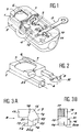
- La Figure 1 représente schématiquement une vue en perspective d'un dispositif selon l'invention en position ouverte correspondant au verrouillage de la clé,
- La Figure 2 représente schématiquement une vue en perspective d'un tiroir de dispositif selon l'invention,
- Les Figures 3A et 3B représentent schématiquement des vues partielles agrandies respectivement de face et selon la flèche 8 de la figure 3A d'un tiroir de dispositif selon l'invention,
- La Figure 4 représente schématiquement un dispositif selon l'invention en position ouverte,
- La Figure 5 représente schématiquement une vue en perspective d'un organe d'encliquetage d'un dispositif selon l'invention,
- La Figure 6 représente schématiquement une vue en perspective partielle agrandie d'une clef pour dispositif selon l'invention,
- Les Figures 7 à 13 représentent schématiquement le fonctionnement d'un dispositif selon l'invention en partant de l'ouverture jusqu'à la fermeture correspondant à la libération de la clef,
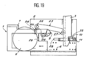
- Les Figures 14 à 19 représentent schématiquement le fonctionnement d'un dispositif selon l'invention en partant d'une position fermée jusqu'à la libération de la pièce de consignation et le verrouillage de la clef.
- FIG. 1 schematically represents a perspective view of a device according to the invention in the open position corresponding to the locking of the key,
- FIG. 2 schematically represents a perspective view of a device drawer according to the invention,
- FIGS. 3A and 3B schematically represent enlarged partial views respectively from the front and according to arrow 8 in FIG. 3A of a device drawer according to the invention,
- FIG. 4 schematically represents a device according to the invention in the open position,
- FIG. 5 schematically represents a perspective view of a latching member of a device according to the invention,
- FIG. 6 schematically represents an enlarged partial perspective view of a key for a device according to the invention,
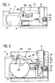
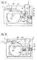
- FIGS. 7 to 13 schematically represent the operation of a device according to the invention, starting from the opening until the closing corresponding to the release of the key,
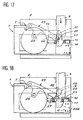
- Figures 14 to 19 schematically represent the operation of a device according to the invention, starting from a closed position until the release of the lockout piece and the locking of the key.
En référence aux figures 1 et 2, un dispositif selon l'invention comporte un tiroir 1 coulissant dans un boîtier 2 apte à recevoir une clef 3 dans une fente de forme correspondante. Le tiroir 1 est monté prisonnier dans le boîtier 2 et est maintenu en position ouverte par un ressort 4 travaillant en compression entre deux faces correspondantes respectivement du tiroir 1 et du boîtier 2. Le tiroir 1 comporte un logement 5 correspondant à une pièce de consignation de type prédéterminé.Referring to Figures 1 and 2, a device according to the invention comprises a
Le tiroir comporte par exemple une barre 6 de maintien de la pièce dans son logement 5, un bossage d'extrémité 7, une lumière 29 correspondant sensiblement à un diamètre du logement 5 de forme essentiellement cylindrique, un organe d'extrémité 9 disposé intérieurement au boîtier 2 lorsque le tiroir est assemblé au boîtier;The drawer comprises for example a bar 6 for holding the part in its
Le boîtier 2 comporte également un verrou 10 maintenu en position de verrouillage de la clef 3 par un ressort 11 ainsi qu'éventuellement un éjecteur 12 consistant par exemple en un ressort d'éjection de la clef disposé sous l'extrémité de la clef lorsque la clef 3 est verrouillée dans le boîtier.The
En référence aux figures 3A et 38, un organe d'extrémité 9 solidaire du tiroir 1 réalisé par exemple directement par usinage de celui-ci comporte un logement d'encliquetage 13 limité par un bec de retenue 14.With reference to FIGS. 3A and 38, an
L'organe 9 comporte deux ergots 15 et 16 en relief par rapport au bec 14 et au bras 17 reliant l'organe 9 au tiroir 1 et au logement 5. L'ergot 15 est limité par un premier plan incliné 18 ou surface analogue portant une pente inclinée selon un angle aigu par rapport au sens d'introduction de la clef, ainsi qu'un autre plan incliné 19 formant un angle prédéterminé en fonction du diamètre du logement 5 de la pièce de consignation.The
Le plan incliné 19 se prolonge par une surface concave 20 qui limite également l'ergot 16 constituant une protubérance supplémentaire par rapport à l'ergot 15. L'ergot 16 est limité par deux plans 21 et 22 : le plan 21 est sensiblement parallèle au sens d'introduction de la clef 3 et le plan 22 est sensiblement parallèle au sens du coulissement du tiroir 1 dans le boîtier 2.The
L'invention se rapporte de préférence à des dispositifs dans lequel le sens du coulissement du tiroir 1 dans le boîtier 2 est sensiblement perpendiculaire au sens d'introduction de la clef 3 dans le boîtier 2, mais il est bien entendu que l'invention s'applique également dans le cas de la non-perpendicularité moyennant des modifications évidentes pour l'homme du métier.The invention preferably relates to devices in which the direction of sliding of the
En référence à la figure 4, on a représenté schématiquement un dispositif selon l'invention comportant des éléments identiques ou similaires et repérés par des chiffres identiques à ceux des figures 1 à 3B.Referring to Figure 4, there is shown schematically a device according to the invention comprising identical or similar elements and identified by numbers identical to those of Figures 1 to 3B.
Un organe d'encliquetage 23 est maintenu en position par un ressort de rappel 24 travaillant par exemple à l'allongement, de manière à ce que l'organe d'encliquetage 23 pivote autour d'un axe 25 solidaire du boîtier sur lequel il est enfilé au moyen de l'alésage correspondant de la figure 5.A latching
Sur la figure 5, des tétons d'extrémités 26 et 27, des cames ou des roulettes analogues, sont rapportés sur l'organe d'encliquetage 23, ou bien venus de matière d'une seule pièce, par exemple directement usinés dans la même ébauche.In FIG. 5, end pins 26 and 27, cams or similar rollers, are attached to the latching
Le verrou 10 maintenu en position de verrouillage de la clef par le ressort 11 est prolongé par un cran 28 correspondant à l'insertion dans la lumière 29 débouchant dans le logement 5 de la pièce de consignation.The
Ainsi le diamètre de la pièce de consignation vient repousser le verrou 10 à l'encontre du ressort 11 pour libérer la clef 3 en appuyant directement sur le cran 28 passant à travers la lumière 29 du logement 5.Thus the diameter of the depositing piece pushes the
En référence à la figure 6, la clef 3 comporte deux ailes perpendiculaires 30 et 31. L'aile 30 coopère avec le verrou 10 au moyen d'un plan incliné d'engagement 32 apte à repousser le verrou 10 jusqu'à ce qu'il s'enclenche sous la pression du ressort 11 dans le logement 33 correspondant à l'épaisseur du verrou 10. A l'exception du plan incliné 32 et du logement 33 en forme de U, la face latérale 34 est sensiblement plane et parallèle au sens d'introduction de la clef.Referring to Figure 6, the
Le plan 35 de l'aile 31 intérieur à l'angle droit formé par les deux ailes 30 et 31 coopère avec la pente inclinée 18 de l'organe 9 du tiroir 1 pour repousser ce tiroir vers l'intérieur du boîtier 2.The
L'aile 31 est échancrée dans son épaisseur par des ouvertures limitées par des plans sensiblement parallèles au sens du coulissement du tiroir 1 dans le boîtier 2 : le premier plan 36 coopère avec le téton 27 de l'organe d'encliquetage 23 pour repousser cet organe d'encliquetage vers le bas en le faisant pivoter à l'encontre du ressort de rappel 24, le plan 37 correspond à la retenue de la clef dans une position intermédiaire dans laquelle le tiroir et la clef sont simultanément prisonniers, la clef étant retenue par appui du plan 37 sur le prolongement sensiblement plan 20a de la surface concave 20 de la figure 3b.The
Le plan 37 coopère également avec le téton 27 de l'organe d'encliquetage 23 pour retenir la clef 3 dans le boîtier 2 dans une autre position intermédiaire décrite ci-après.The
L'évidement 38 sensiblement en forme de L correspond au passage de l'organe d'extrémité 9 à travers la clef.The substantially L-shaped
En référence aux figures 7 à 13, le tiroir 1 est maintenu en position ouverte par le ressort 4, tandis que la clef 3 est retenue par le verrou 10 appuyé par le ressort 11 dans le logement 33, l'éjecteur 12, prenant appui sur l'extrémité inférieure 39 (figure 6) de la clef, n'étant pas représenté.Referring to Figures 7 to 13, the
Dans la position de la figure 7, le téton 26 de l'organe d'encliquetage 23 est maintenu en position basse par le ressort 24 : si l'on pousse le tiroir 1 dans le sens de la fermeture, l'extrémité et le téton 26 de l'organe d'encliquetage 23 butent contre le bossage 7 du tiroir 1 constituant de ce fait une butée de translation à la fermeture en l'absence de pièce de consignation ou en présence d'une pièce non conforme au type requis.In the position of FIG. 7, the
Après avoir placé une pièce conforme au type requis dans le logement 5 et après avoir poussé le tiroir 1 dans le sens de la fermeture, le téton 26 de l'organe d'encliquetage 23 suit le contour extérieur de la pièce de consignation soulevant l'extrémité 26, de sorte que le téton 27 et l'extrémité correspondante passent à travers les échancrures de l'aile 31 de la clef 3, le téton 27 suivant tout d'abord le plan incliné 19 de pente prédéterminée en fonction du diamètre de la pièce de consignation, puis la surface concave 20 en enveloppant ainsi le contour extérieur de l'organe d'extrémité 9 du tiroir 1.After placing a part conforming to the required type in the
Sur la Figure 8, le téton 27 atteint une position basse correspondant à la position la plus haute du téton 26 sur le contour de la pièce de consignation.In Figure 8, the
En poussant davantage le tiroir 1, le téton 26 redescend ce qui provoque, du fait du pivotement du levier 23 autour l'axe 25, un relèvement du téton 27 qui vient se loger dans le logement d'encliquetage 13 de l'organe d'extrémité 9. Dans cette position intermédiaire représentée à la figure 9, l'organe d'encliquetage 23, solidaire du boîtier 2, retient le tiroir 1 dans une position dans laquelle la clef 3 et la pièce de consignation sont simultanément prisonnières du dispositif : en effet, la clef est à la fois retenue par le verrou 10 coopérant avec le logement 33 de la clef 3 et simultanément par l'appui du plan 20a du tiroir 1 sur le plan 37 de la clef 3, tandis que le tiroir 1 contenant la pièce de consignation dans son logement 5 est retenu par l'appui du téton 27 arc-bouté dans le logement 13 de l'organe d'extrémité 9 du tiroir 1.By pushing the
A partir de la position intermédiaire de la figure 9, on exerce une poussée supplémentaire sur le tiroir 1 : cet enfoncement provoque le chevauchement de la butée 7 par l'extrémité du levier 23 correspondant au téton 26 ; par effet de levier, le téton 27 s'abaisse, tandis que l'organe d'extrémité 9 traverse complètement l'aile 31 de la clef 3 et que la pièce de consignation vient appuyer directement sur l'ergot 28 du verrou 10 et repousse seule le verrou à l'encontre du ressort 11 d'une distance suffisante pour permettre le dégagement de la clef 3. Toutefois dans cette position, le téton 27 du levier 23 est encore en appui sur l'arête du plan 37 de la clef 3, comme représenté à la figure 10.From the intermediate position in FIG. 9, an additional thrust is exerted on the slide 1: this depression causes the
En référence à la figure 11, lorsque l'on continue le mouvement de poussée vers l'intérieur le bossage 7 soulève le téton 26 qui provoque l'abaissement du téton opposé 27 de l'organe d'encliquetage 23. Cet abaissement et pivotement de l'extrémité 27 dégage le plan d'appui 37 de la clef 3 : la clef 3 entièrement libérée est alors repoussée vers l'extérieur par un éjecteur 12 comportant par exemple un ressort symbolisé par la flèche de la figure 11.With reference to FIG. 11, when the pushing movement is continued inwards, the
En référence à la figure 12, après que la clef 3 soit libérée en passant entre l'organe d'extrémité 9 du tiroir 1 et l'extrémité 27 du levier 23, le tiroir 1 se dégage à l'extérieur sous l'action du ressort 4 simultanément, le levier 23 est ramené en position par le ressort de rappel 24 de manière à se trouver sensiblement au contact de l'extrémité du bec 14 de l'organe d'extrémité 9.Referring to Figure 12, after the
En référence à la figure 13, un relâchement complet du tiroir 1 provoque l'encliquetage du téton 27 dans le logement 13 de l'organe d'extrémité 9 du tiroir : le tiroir est ainsi encliqueté et la pièce de consignation disposée dans le logement 5 reste prisonnière à l'intérieur du dispositif.Referring to Figure 13, a complete relaxation of the
En partant de la figure 7 dans laquelle le tiroir est ouvert et la clef prisonnière du verrou 10, on arrive ainsi en passant par une étape représentée à la figure 9 correspondant a une position intermédiaire d'encliquetage dans laquelle la clef et le tiroir sont simultanément prisonniers du boîtier à une étape représentée à la figure 13 dans laquelle la clef est dégagée du dispositif et la pièce de monnaie est consignée à l'intérieur du dispositif.Starting from FIG. 7 in which the drawer is open and the key trapped in the
En référence à la figure 14, la pièce de monnaie contenue dans le logement 5 du tiroir est prisonnière à l'intérieur du dispositif, du fait que le tiroir est retenu par l'organe d'encliquetage 23, en particulier du fait que l'extrémité 27 du levier 23 arc-bouté à l'intérieur du logement d'encliquetage 13 de l'organe d'extrémité 9 du tiroir retient celui-ci à l'intérieur du boîtier 2 à l'encontre du ressort 4 d'ouverture du tiroir.Referring to Figure 14, the coin contained in the
En référence à la figure 15, la clef 3 s'engageant le long du plan incliné 18 formant un angle aigu avec la direction d'introduction de la clef repousse le tiroir 1 dans le sens de la fermeture puis dégage l'extrémité 27 du levier 23 et repousse cette extrémité 27 vers le bas par appui du plan 36 sur ladite extrémité 27 : la clef 3 s'engage ainsi entre l'organe d'extrémité 9 et l'organe d'encliquetage 23 en les séparant l'un de l'autre et en les repoussant en sens opposé l'un à l'autre.Referring to Figure 15, the
Cette action de la clef provoque le désencliquetage du tiroir 1.This action of the key causes the
En référence à la figure 16, la clef 3 appuie par son plan 36 sur l'extrémité 27 du levier 23 et repousse ainsi celui-ci vers le bas. Le tiroir 1 désencliqueté recule jusqu'à une position dans laquelle l'ergot 16 de l'organe d'extrémité 9 est retenu par l'appui du plan 21 sur la face intérieure de l'aile 31, c'est-à-dire le plan 35. Simultanément la clef s'engage par le plan incliné 32 de l'aile 30 dans l'orifice correspondant du verrou 10 et repousse ainsi le verrou 10 à l'encontre du ressort 11.Referring to Figure 16, the key 3 presses by its
En référence à la figure 17, un enfoncement de la clef 3 provoque le glissement le long de la face extérieure de l'aile 31 de l'extrémité 27 de l'organe d'encliquetage 23 jusqu'à une position dans laquelle l'extrémité 27 retient la clef par coopération avec le plan 37, tout en passant sous le bec 14 et en évitant ainsi un encliquetage accidentel dans le logement 13.Referring to Figure 17, a depression of the key 3 causes the sliding along the outer face of the
Dans cette position intermédiaire, la clef 3 retient le tiroir 1 par la coopération des plans 21 du tiroir 1 et 35 de la clef 3, tandis que l'extrémité 27 du levier 23 retenu par le plan 20a de l'organe d'extrémité 9, retient à son tour la clef 3 en appuyant sur le plan 37.In this intermediate position, the
Dans cette position intermédiaire, dans laquelle la clef 3 et la pièce de consignation sont simultanément prisonnières du dispositif, la seule possibilité d'actionnement correspond à un enfoncement de la clef 3.In this intermediate position, in which the
En référence à la figure 18, un enfoncement de la clef 3 aboutit au verrouillage par engagement du verrou 10 dans le logement 33 de la clef sous la poussée du ressort 11 correspondant. Dans cette position, l'extrémité 27 du levier 23 est en équilibre sur le plan 20a de l'organe d'extrémité 9 du tiroir 1. En enfonçant encore légèrement la clef, l'organe d'extrémité 9 s'échappe par l'échancrure 38 en forme de L ménagée dans l'aile 31 de la clef 3 et correspondant au passage des ergots 15 et 16 ; le recul du tiroir 1 permet ensuite le contournement par le téton 27 des surfaces 20 et 19 : de ce fait les ressorts 4 et 24 ne sont plus sous contrainte et peuvent exercer leur action de rappel respectivement sur le tiroir 1 et sur le levier 23.Referring to Figure 18, a depression of the key 3 results in locking by engagement of the
En référence à la figure 19, les ressorts 4 et 24 rappellent le tiroir 1 en position d'ouverture et le levier 23 en position d'abaissement de l'extrémité 26 et de relèvement de l'extrémité 27. Le recul du tiroir permet ainsi l'accès au logement 5 de la pièce de consignation et le retrait de la pièce de consignation.Referring to Figure 19, the
Ainsi en partant d'une position représentée à la figure 14 où la pièce de consignation est prisonnière en position d'encliquetage du tiroir 1 par l'organe d'encliquetage 23, on aboutit en passant par une étape intermédiaire représentée à la figure 17 où la pièce et la clef sont simultanément prisonnières du dispositif, à une étape finale représentée à la figure 19 dans laquelle la clef est prisonnière du dispositif et la pièce de consignation peut être retirée du logement 5 du tiroir 1 ouvert.Thus, starting from a position represented in FIG. 14 where the depositing piece is trapped in the latching position of the
L'invention est également relative à des chariots encastrables comportant un dispositif décrit en référence aux figures 1 à 19. De préférence, on fixe le dispositif à la barre de poussée d'un chariot encastrable de manière à ce que la direction du coulissement du tiroir soit parallèle à l'axe longitudinal de la barre du chariot ou de manière à ce que le sens d'introduction de la clef soit sensiblement perpendiculaire audit axe longitudinal de la barre du chariot.The invention also relates to built-in carriages comprising a device described with reference to FIGS. 1 to 19. Preferably, the device is fixed to the push bar of a built-in cart so that the direction of sliding of the drawer is parallel to the longitudinal axis of the carriage bar or in such a way that the direction of insertion of the key is substantially perpendicular to said longitudinal axis of the carriage bar.
De préférence et de manière connue, on relie une clef par une chaîne ou un lien souple analogue à un boîtier d'un chariot : le dispositif est adapté par ajustement de la longueur du lien souple pour que l'on puisse insérer une clef dans la fente d'un chariot voisin et que l'on ne puisse pas l'insérer dans la fente du boîtier à laquelle elle est reliée par le lien souple.Preferably and in a known manner, a key is connected by a chain or a flexible link similar to a box of a carriage: the device is adapted by adjusting the length of the flexible link so that a key can be inserted into the slot of a neighboring carriage and that it cannot be inserted into the slot of the housing to which it is connected by the flexible link.
Ainsi, après avoir encastré un premier chariot avec un deuxième chariot, la clef du premier chariot coopère avec la fente du boîtier du deuxième chariot encastré avec le premier. Lorsque le boîtier du deuxième chariot est dans la position représentée à la figure 14, la clef engagée dans la fente du boîtier repousse successivement le tiroir vers l'intérieur du boîtier, l'organe d'encliquetage correspondant à l'encontre du ressort associé et le verrou 10 correspondant à l'encontre du ressort associé, de manière à verrouiller les chariots l'un à l'autre et provoquer l'ouverture du tiroir, ce qui permet d'extraire la pièce de consignation de son logement comme représenté à la figure 19.Thus, after having embedded a first carriage with a second carriage, the key of the first carriage cooperates with the slot in the housing of the second carriage embedded with the first. When the housing of the second carriage is in the position shown in FIG. 14, the key engaged in the slot of the housing successively pushes the drawer towards the interior of the housing, the latching member corresponding against the associated spring and the
Dans ce cas, le deuxième chariot se retrouve avec un boîtier correspondant à la position de la figure 7. Il suffit alors de placer une pièce de consignation de type déterminé dans le logement 5 du boîtier. La pièce de consignation introduite dans le logement du tiroir, le tiroir étant ensuite repousse dans le boîtier, actionne un déplacement de l'organe d'encliquetage jusqu'à une position intermédiaire stable dans laquelle le tiroir est retenu par encliquetage dans le boîtier à l'encontre du ressort 4 de rappel à l'ouverture.In this case, the second carriage is left with a box corresponding to the position in FIG. 7. It then suffices to place a deposit piece of determined type in the
Comme représenté à la figure 9, dans cette position d'encliquetage stable du tiroir dans le boîtier, la clef et le tiroir sont en prise l'un avec l'autre par des conformations correspondantes empêchant le dégagement du tiroir et de la clef. Dans cet exemple, les conformations correspondent à l'appui du plan 20a sur le plan 37 et à l'appui du plan 21 sur le plan 35 : il est bien entendu que l'invention s'applique également à toute variante de réalisation ou modification de forme de ces appuis présentant des directions perpendiculaires sensiblement parallèles respectivement au sens de coulissement du tiroir et au sens d'introduction de la clef.As shown in Figure 9, in this stable snap-in position of the drawer in the housing, the key and the drawer are engaged with each other by corresponding conformations preventing the release of the drawer and the key. In this example, the conformations correspond to the support of the
Une poussée supplémentaire sur le tiroir contenant une pièce de consignation provoque le repoussage du verrou: dans ce cas particulier, la pièce de consignation introduite dans le logement du tiroir repoussée à fond dans le boîtier repousse directement le verrou de la clef à l'encontre du ressort correspondant grâce à l'appui de la tranche de la pièce elle-même sur l'ergot 28 du verrou 10 passant à travers la lumière 29 débouchant dans le logement 5.An additional push on the drawer containing a lockout piece causes the lock to be pushed back: in this particular case, the lockout piece introduced into the drawer housing pushed back fully into the housing directly pushes the key lock against the corresponding spring by pressing the edge of the part itself on the
La clef est ainsi directement déverrouillée par appui de la pièce de consignation sur un cran solidaire du verrou.The key is thus directly unlocked by pressing the deposit piece on a notch secured to the lock.
Après déverrouillage de la clef, celle-ci reste retenue par une conformation telle que le plan 37 réalisé sur l'aile 31 de la clef coopérant avec le tiroir et l'organe d'encliquetage. Lorsque l'on pousse à fond le tiroir contenant la pièce de consignation, on provoque des déplacements simultanés de conformations de retenue de la clef situées de part et d'autre de celle-ci. Ces conformations ménagées respectivement sur le tiroir et sur l'organe d'encliquetage s'écartent et permettent ainsi la libération de la clef. La clef passe entre lesdites conformations de retenue, en étant par exemple repoussée par un éjecteur formant ressort.After unlocking the key, it remains retained by a conformation such as the
Ainsi, le dispositif selon l'invention passe toujours par une position intermédiaire d'encliquetage dans laquelle la clef et la pièce de consignation sont simultanément retenues prisonnières du boîtier.Thus, the device according to the invention always passes through an intermediate latching position in which the key and the locking piece are simultaneously trapped in the housing.
Grâce à cette étape intermédiaire d'encliquetage, on évite ainsi les inconvénients de l'Art antérieur du fait que les moyens de retenue multiples de la clef et du tiroir renforcent la sécurité du système et empêchent les manoeuvres brutales de déverrouillage au moyen d'un outil ou d'arrachement de la clef hors de la fente correspondante du boîtier.Thanks to this intermediate latching step, the drawbacks of the prior art are thus avoided, since the multiple means for retaining the key and the drawer reinforce the security of the system and prevent brutal unlocking operations by means of a tool or wrench wrench out of the corresponding slot in the housing.
De plus, du fait que la pièce de consignation actionne directement l'organe d'encliquetage et le verrou de la clef, ce dispositif fournit un moyen de contrôle du contour de la pièce placée dans le logement 5 et du diamètre de la pièce appuyant sur l'ergot 28 passant à travers la lumière 29. Il est donc nécessaire, pour faire fonctionner le dispositif selon l'invention, de placer une pièce du type requis dans le logement 5. Le fonctionnement du dispositif au moyen d'objets présentant une géométrie différente de celle de la pièce de consignation est ainsi exclus.In addition, the fact that the locking piece directly actuates the latching member and the key lock, this device provides a means of controlling the outline of the piece placed in the
La présente invention a été décrite en référence à des modes de réalisation particuliers ; l'invention n'y est nullement limitée, mais englobe au contraire toute modification de forme et toute variante de réalisation dans le cadre de l'invention, relative à un dispositif dans lequel une position d'encliquetage correspondant à un emprisonnement simultané de la clef et de la pièce de consignation est obtenue. L'organe d'encliquetage 23 conformé en levier peut adopter toute forme mécaniquement équivalente en conjonction avec les mouvements relatifs du tiroir et de la clef dans le boîtier. Ainsi l'organe d'encliquetage pourra se déplacer en translation, dans le cas où au moins la clef ou le tiroir seront soumis à un mouvement de pivotement ou un mouvement cinématiquement équivalent.The present invention has been described with reference to particular embodiments; the invention is in no way limited thereto, but on the contrary includes any modification of form and any variant embodiment within the framework of the invention, relating to a device in which a latching position corresponding to a simultaneous imprisonment of the key and a deposit is obtained. The latching
Claims (31)
- Deposit device, in particular for a trolley, comprising a drawer (1) sliding in a casing (2) against a return spring, the drawer (1) comprising a housing (5) for a deposit piece of a predetermined type, the casing (2) comprising a lock (10) for a key (3) or a similar coupling device and the drawer (1) sliding substantially perpendicular to the direction of the introduction of the key (3) in a slot of the casing (2), characterised in that a latching device (23) firmly fixed to the casing (2) holds the drawer (1) in a stable intermediate position in which the key (3) and the drawer (1) are simultaneously trapped by the casing (2).
- Device according to claim 1, characterised in that the housing (5) of the deposit piece and the lock (10) of the key (3) have conformations (28, 29) corresponding to the direct support of the piece on the lock (10).
- Device according to claim 2, characterised in that the latching device (23) comprises an end having a conformation (26) in the form of a dog point, cam or similar guide able to follow a trajectory predetermined according to the peripheral contour of the deposit piece.
- Device according to claim 3, for a deposit piece in the form of a flat disc, characterised in that the said end (26) moves in an arc of a circle.
- Device according to any one of the preceding claims, characterised in that the latching device (23) comprises an end inside the casing (2) having a second conformation (27) in the form of a dog point, cam or similar guide able to follow the contour (19, 20) of one end (9) of the drawer (1) inside the casing (2).
- Device according to claim 5, characterised in that the second conformation (27) cooperates with a latching housing (13) of the drawer (1) in order to hold the drawer (1) in the stable intermediate position.
- Device according to all the preceding claims, characterised in that the latching device (23) is in the form of a lever articulated between its two ends (26, 27) so as to pivot about an axis (25) firmly fixed to the casing (2).
- Device according to claim 7, characterised in that the lever (23) is held in a predetermined position by a return spring (24) or the like.
- Device according to claim 8, characterised in that the return spring (24) or the like is adjacent to the end (26) of the lever (23) corresponding to the following of the contour of the deposit piece.
- Device according to any one of the preceding claims, characterised in that the drawer (1) comprises a projection (7) forming a translation stop coming into contact with the latching device (23) when the drawer (1) is closed without the deposit piece of the predetermined type.
- Device according to claim 10, characterised in that the drawer (1) comprises an end device (9) which is able to cross a wing (31) of the key (3) by passing into notches (38) or conformations of a corresponding shape and is attached by an arm (17) to the housing (5) of the deposit piece.
- Device according to claim 11, characterised in that the end device (9) has a projection (14) defining a latching housing (13).
- Device according to claim 10 or claim 11, characterised in that the end device (9) comprises a first projecting toe (15) and a second toe (16) in relief with respect to the first toe (15).
- Device according to claim 13, characterised in that the first toe (15) comprises an inclined plane (18) forming an acute angle with the direction of introduction of the key, in such a way as to push the drawer (1) towards the inside of the casing (2) by means of a wing (31) of the key (3) sliding in the introduction direction along the said inclined plane (18).
- Device according to claim 13 or claim 14, characterised in that the end contour of the first toe (15) comprises at least one surface (20) corresponding to the trajectory of one end (27) of the latching device (23).
- Device according to any of claims 13 to 15, characterised in that the second toe (16) is limited by two perpendicular planes (21, 22) which are respectively parallel to the direction of the introduction of the key (3) and the direction in which the drawer (1) slides.
- Device according to any of the preceding claims, characterised in that the lock (10) comprises a toe (28) and that the housing (5) of the piece has a corresponding hole (29) so that the deposit piece pushes directly onto the toe (28) of the lock (10) passing into the hole (29) of the housing in the closed position of the drawer (1).
- Device according to any of the preceding claims, characterised in that in the stable intermediate position corresponding to the latching, the drawer (1) and the key (3) have corresponding first conformations (20a, 33) preventing the retraction of the key (3) and corresponding second conformations (21, 35) preventing the opening of the drawer (1).
- Device according to any of the preceding claims, characterised in that the key (3) comprises a wing (31) having notches or conformations corresponding to the passage of one end (27) of the latching device (23) through the wing (31) of the key (3).
- Device according to any of the preceding claims, characterised in that the key comprises a wing (30) having an inclined plane (32) for engagement and for pushing on the lock (10) and a locking housing (33) corresponding to the said lock (10).
- Device according to claim 19 and claim 20, characterised in that the key comprises two substantially perpendicular wings (30, 31).
- Device according to claim 21, characterised in that the first wing (31) of the key cooperates with the drawer (1) and the latching device (23) and in that the second wing (30) of the key cooperates with the lock (10).
- Device according to claim 22 and claim 13, characterised in that the first wing (31) of the key has a notch (38) in an L shape corresponding to the passage of the two toes (15, 16) through the wing (31) of the key.
- Device according to claim 22 or 23, characterised in that the first wing (31) of the key (3) has a support plane (36) on the latching device (23), or a similar conformation by means of which the key (3) pushes back the latching device (23).
- Device according to any of the preceding claims, characterised in that an ejector (12) for the key (3) is permanently mounted in the casing (2) in order to push back the unlocked key (3) out of the casing (2), the ejector comprising elastic means such as a spring.
- Nesting trolley comprising a device in accordance with any of the preceding claims fixed to the pushing bar of the trolley, characterised in that the sliding direction of the drawer (1) is parallel to the longitudinal axis of the bar of the trolley and in that the direction of the introduction of the key (3) is substantially perpendicular to the said longitudinal axis.
- Trolley according to claim 26, characterised in that the key (3) firmly fixed to a first trolley by means of a chain or similar connection fixed to the casing (2) cooperates with the corresponding slot of the casing (2) of a second trolley nested in the first trolley by successively pushing back the corresponding drawer (1) towards the inside of the casing (2), the corresponding latching device (23) against a corresponding spring (24) or the like and the corresponding lock (10) against a corresponding spring (11) or return means, in such a way as to connect the trolleys to each other and to open the drawer (1) to extract the deposit piece from its housing (5).
- Trolley according to claim 26 or claim 27, characterised in that a deposit piece introduced into the housing (5) of the drawer (1) pushed back in the casing (2) actuates a movement of the latching device (23) as far as a stable intermediate position in which the drawer (1) is held by latching in the casing (2) against a spring (4) or return means at the corresponding opening.
- Trolley according to claim 28, characterised in that in that in the stable latching position of the drawer (1) in the casing (2), the key (3) and the drawer (1) are engaged with each other by corresponding conformations (20a, 37; 21, 35) preventing the release of the drawer (1) and of the key (3).
- Trolley according to any of claims 26 to 29, characterised in that a deposit piece introduced into the housing (5) of the drawer (1) pushed right into the casing pushes back the lock (10) of the key (3) against the corresponding spring (11) in such a way as to unlock the key (3).
- Trolley according to claim 30, characterised in that after unlocking the key (3) remaining held by a conformation (37), a push right on the drawer (1) containing the deposit piece simultaneously causes movements on both sides of the key (3) of corresponding respective conformations (20a, 27) of the drawer (1) and of the latching device (23) in such a way as to permit the freeing of the key (3) passing between the said holding conformations (20a, 27).
Applications Claiming Priority (2)
| Application Number | Priority Date | Filing Date | Title |
|---|---|---|---|
| FR9208087A FR2693297B1 (en) | 1992-07-01 | 1992-07-01 | Lockout device and built-in cart comprising such a device. |
| FR9208087 | 1992-07-01 |
Publications (2)
| Publication Number | Publication Date |
|---|---|
| EP0577472A1 EP0577472A1 (en) | 1994-01-05 |
| EP0577472B1 true EP0577472B1 (en) | 1995-05-31 |
Family
ID=9431394
Family Applications (1)
| Application Number | Title | Priority Date | Filing Date |
|---|---|---|---|
| EP19930401612 Expired - Lifetime EP0577472B1 (en) | 1992-07-01 | 1993-06-23 | Coin lock for returnable article and a trolley which nestles inside another provided with such a device |
Country Status (3)
| Country | Link |
|---|---|
| EP (1) | EP0577472B1 (en) |
| DE (1) | DE69300170T2 (en) |
| FR (1) | FR2693297B1 (en) |
Families Citing this family (4)
| Publication number | Priority date | Publication date | Assignee | Title |
|---|---|---|---|---|
| DE19600248C1 (en) * | 1996-01-05 | 1997-07-31 | Boehringer Rainer | Deposit lock |
| ATE302984T1 (en) * | 1998-05-08 | 2005-09-15 | Assa Ab | CARD LOCK |
| IT1403642B1 (en) * | 2011-01-21 | 2013-10-31 | Bailini | LOCKING DEVICE, SHOPPING TROLLEY USING THIS LOCKING DEVICE, REALIZATION PROCEDURE AND USE OF THE LOCKING DEVICE |
| IT1403641B1 (en) * | 2011-01-21 | 2013-10-31 | Bailini | LOCKING DEVICE, SHOPPING TROLLEY USING THIS LOCKING DEVICE, REALIZATION PROCEDURE AND USE OF THE LOCKING DEVICE |
Family Cites Families (7)
| Publication number | Priority date | Publication date | Assignee | Title |
|---|---|---|---|---|
| FR2604010B2 (en) * | 1984-12-27 | 1990-03-02 | Maloeuvre Robert | COIN, IN PARTICULAR FOR SUPERMARKET TROLLEYS |
| FR2575569B1 (en) * | 1984-12-27 | 1988-06-10 | Maloeuvre Robert | METHOD AND DEVICE FOR INCENTING THE STORAGE OF SELF-SERVICE TROLLEYS |
| US4691816A (en) * | 1985-09-19 | 1987-09-08 | Cari-All Inc. | Locking device for interlocking nested shopping carts |
| DK163387C (en) * | 1988-12-20 | 1992-07-13 | Catena Systems Aps | MOUNTING WELDING AUTOMATIC FOR DELIVERY OF A LASTE ORGANIC LISTED IN THE AUTOMATIC |
| FR2645306B1 (en) * | 1989-03-31 | 1992-04-10 | Mors | LOCKER AND DISSIGNER DEVICE FOR UTILITY OBJECTS, SUCH AS LUGGAGE CARTS |
| DE3912831A1 (en) * | 1989-04-19 | 1990-10-25 | Wanzl Entwicklung Gmbh | COIN LOCK FOR TRANSPORT CARS |
| US5040656A (en) * | 1990-01-31 | 1991-08-20 | Dipaolo Anthony M | Coin-controlled apparatus for locking shopping carts together |
-
1992
- 1992-07-01 FR FR9208087A patent/FR2693297B1/en not_active Expired - Fee Related
-
1993
- 1993-06-23 EP EP19930401612 patent/EP0577472B1/en not_active Expired - Lifetime
- 1993-06-23 DE DE1993600170 patent/DE69300170T2/en not_active Expired - Fee Related
Also Published As
| Publication number | Publication date |
|---|---|
| FR2693297A1 (en) | 1994-01-07 |
| EP0577472A1 (en) | 1994-01-05 |
| DE69300170D1 (en) | 1995-07-06 |
| DE69300170T2 (en) | 1995-10-19 |
| FR2693297B1 (en) | 1994-08-26 |
Similar Documents
| Publication | Publication Date | Title |
|---|---|---|
| EP1644604B1 (en) | Latch for joining two panels of an airplane structure | |
| EP0341174B1 (en) | Latch assembly, especially for sliding wings | |
| EP0040132B1 (en) | Safety belt buckle | |
| EP0577472B1 (en) | Coin lock for returnable article and a trolley which nestles inside another provided with such a device | |
| CA1145174A (en) | Safety device for the release of a load suspended from an aircraft carrying said load, and load thus fitted | |
| EP2960406B1 (en) | Device for opening and closing an article, especially made of leather, and article comprising such a device | |
| FR2645306A1 (en) | Deposit taking and returning device for utility objects, such as luggage trolleys | |
| CA1285784C (en) | Cart rental installation | |
| FR2738864A1 (en) | Combination lock, e.g. for luggage with sliding clasp fasteners | |
| EP0415805B1 (en) | Consignment deposit for rigid fixing type of trolleys and trolleys provided with such a device | |
| WO1988007615A1 (en) | Lock with locking-unlocking mechanism using an electromagnet | |
| WO2002025041A1 (en) | Mechanism for manoeuvring a door | |
| FR2601062A1 (en) | Locking latch with pivoting bolt, intended in particular for a part comprising a panic bolt | |
| WO1996013019A1 (en) | Coin deposit lock for trolleys | |
| EP3724429B1 (en) | Handle support for a motor vehicle | |
| LU85571A1 (en) | LOCKER AND DISSIGNER DEVICE FOR UTILITY OBJECTS SUCH AS LUGGAGE CARTS | |
| EP0354107B1 (en) | Fastening device for rapidly docking a structure thereto in a detachable way | |
| FR2845718A1 (en) | Lock for high security sliding door, comprises bolt which is spring loaded towards a locked position, an operating plate with articulated latch to engage with fixed lug and door detecting finger | |
| EP3588526B1 (en) | Fuse holder | |
| EP1049847B1 (en) | Anti-theft case | |
| FR2850697A1 (en) | Door lock for building, has maintenance unit to maintain immobilization unit in releasing configuration, where immobilization unit immobilizes locking unit when dead bolt is in locking position | |
| EP1620853A2 (en) | Anti-theft device for case | |
| FR2530715A1 (en) | Safety lock with lockable rotary barrel. | |
| FR2826682A1 (en) | Lock e.g. for fire door has door frame detector that releases bolt when door is in closed position | |
| FR2763722A3 (en) | Coin return lock for supermarket trolleys |
Legal Events
| Date | Code | Title | Description |
|---|---|---|---|
| PUAI | Public reference made under article 153(3) epc to a published international application that has entered the european phase |
Free format text: ORIGINAL CODE: 0009012 |
|
| AK | Designated contracting states |
Kind code of ref document: A1 Designated state(s): BE DE DK ES GB IT LU NL SE |
|
| 17P | Request for examination filed |
Effective date: 19931223 |
|
| 17Q | First examination report despatched |
Effective date: 19941111 |
|
| GRAA | (expected) grant |
Free format text: ORIGINAL CODE: 0009210 |
|
| AK | Designated contracting states |
Kind code of ref document: B1 Designated state(s): BE DE DK ES GB IT LU NL SE |
|
| PG25 | Lapsed in a contracting state [announced via postgrant information from national office to epo] |
Ref country code: NL Free format text: LAPSE BECAUSE OF FAILURE TO SUBMIT A TRANSLATION OF THE DESCRIPTION OR TO PAY THE FEE WITHIN THE PRESCRIBED TIME-LIMIT Effective date: 19950531 Ref country code: IT Free format text: LAPSE BECAUSE OF FAILURE TO SUBMIT A TRANSLATION OF THE DESCRIPTION OR TO PAY THE FEE WITHIN THE PRE;WARNING: LAPSES OF ITALIAN PATENTS WITH EFFECTIVE DATE BEFORE 2007 MAY HAVE OCCURRED AT ANY TIME BEFORE 2007. THE CORRECT EFFECTIVE DATE MAY BE DIFFERENT FROM THE ONE RECORDED.SCRIBED TIME-LIMIT Effective date: 19950531 Ref country code: ES Free format text: THE PATENT HAS BEEN ANNULLED BY A DECISION OF A NATIONAL AUTHORITY Effective date: 19950531 Ref country code: DK Effective date: 19950531 |
|
| GBT | Gb: translation of ep patent filed (gb section 77(6)(a)/1977) |
Effective date: 19950605 |
|
| REF | Corresponds to: |
Ref document number: 69300170 Country of ref document: DE Date of ref document: 19950706 |
|
| PG25 | Lapsed in a contracting state [announced via postgrant information from national office to epo] |
Ref country code: SE Effective date: 19950831 |
|
| NLV1 | Nl: lapsed or annulled due to failure to fulfill the requirements of art. 29p and 29m of the patents act | ||
| PLBE | No opposition filed within time limit |
Free format text: ORIGINAL CODE: 0009261 |
|
| STAA | Information on the status of an ep patent application or granted ep patent |
Free format text: STATUS: NO OPPOSITION FILED WITHIN TIME LIMIT |
|
| 26N | No opposition filed | ||
| PGFP | Annual fee paid to national office [announced via postgrant information from national office to epo] |
Ref country code: BE Payment date: 19980511 Year of fee payment: 6 |
|
| PGFP | Annual fee paid to national office [announced via postgrant information from national office to epo] |
Ref country code: GB Payment date: 19980615 Year of fee payment: 6 |
|
| PGFP | Annual fee paid to national office [announced via postgrant information from national office to epo] |
Ref country code: LU Payment date: 19980617 Year of fee payment: 6 |
|
| PG25 | Lapsed in a contracting state [announced via postgrant information from national office to epo] |
Ref country code: LU Free format text: LAPSE BECAUSE OF NON-PAYMENT OF DUE FEES Effective date: 19990623 Ref country code: GB Free format text: LAPSE BECAUSE OF NON-PAYMENT OF DUE FEES Effective date: 19990623 |
|
| PG25 | Lapsed in a contracting state [announced via postgrant information from national office to epo] |
Ref country code: BE Free format text: LAPSE BECAUSE OF NON-PAYMENT OF DUE FEES Effective date: 19990630 |
|
| BERE | Be: lapsed |
Owner name: ATELIERS REUNIS CADDIE Effective date: 19990630 |
|
| GBPC | Gb: european patent ceased through non-payment of renewal fee |
Effective date: 19990623 |
|
| PGFP | Annual fee paid to national office [announced via postgrant information from national office to epo] |
Ref country code: DE Payment date: 20030428 Year of fee payment: 11 |
|
| PG25 | Lapsed in a contracting state [announced via postgrant information from national office to epo] |
Ref country code: DE Free format text: LAPSE BECAUSE OF NON-PAYMENT OF DUE FEES Effective date: 20050101 |