EP0577111A2 - Safety shutter device for drawout type switch gear - Google Patents
Safety shutter device for drawout type switch gear Download PDFInfo
- Publication number
- EP0577111A2 EP0577111A2 EP93110470A EP93110470A EP0577111A2 EP 0577111 A2 EP0577111 A2 EP 0577111A2 EP 93110470 A EP93110470 A EP 93110470A EP 93110470 A EP93110470 A EP 93110470A EP 0577111 A2 EP0577111 A2 EP 0577111A2
- Authority
- EP
- European Patent Office
- Prior art keywords
- shutter
- base frame
- pair
- driving unit
- rod
- Prior art date
- Legal status (The legal status is an assumption and is not a legal conclusion. Google has not performed a legal analysis and makes no representation as to the accuracy of the status listed.)
- Granted
Links
- 239000004020 conductor Substances 0.000 claims abstract description 23
- 238000003780 insertion Methods 0.000 claims abstract description 14
- 230000037431 insertion Effects 0.000 claims abstract description 14
- 230000006835 compression Effects 0.000 claims description 5
- 238000007906 compression Methods 0.000 claims description 5
- 238000007689 inspection Methods 0.000 description 5
- 238000012423 maintenance Methods 0.000 description 3
- 230000000717 retained effect Effects 0.000 description 3
- 230000004075 alteration Effects 0.000 description 2
- 238000009434 installation Methods 0.000 description 2
- 238000012986 modification Methods 0.000 description 2
- 230000004048 modification Effects 0.000 description 2
- 230000000694 effects Effects 0.000 description 1
- 239000002184 metal Substances 0.000 description 1
- NJPPVKZQTLUDBO-UHFFFAOYSA-N novaluron Chemical group C1=C(Cl)C(OC(F)(F)C(OC(F)(F)F)F)=CC=C1NC(=O)NC(=O)C1=C(F)C=CC=C1F NJPPVKZQTLUDBO-UHFFFAOYSA-N 0.000 description 1
- 230000008520 organization Effects 0.000 description 1
- 230000002265 prevention Effects 0.000 description 1
Images


Classifications
-
- H—ELECTRICITY
- H02—GENERATION; CONVERSION OR DISTRIBUTION OF ELECTRIC POWER
- H02B—BOARDS, SUBSTATIONS OR SWITCHING ARRANGEMENTS FOR THE SUPPLY OR DISTRIBUTION OF ELECTRIC POWER
- H02B1/00—Frameworks, boards, panels, desks, casings; Details of substations or switching arrangements
-
- H—ELECTRICITY
- H02—GENERATION; CONVERSION OR DISTRIBUTION OF ELECTRIC POWER
- H02B—BOARDS, SUBSTATIONS OR SWITCHING ARRANGEMENTS FOR THE SUPPLY OR DISTRIBUTION OF ELECTRIC POWER
- H02B11/00—Switchgear having carriage withdrawable for isolation
- H02B11/24—Shutters or guards
-
- H—ELECTRICITY
- H02—GENERATION; CONVERSION OR DISTRIBUTION OF ELECTRIC POWER
- H02B—BOARDS, SUBSTATIONS OR SWITCHING ARRANGEMENTS FOR THE SUPPLY OR DISTRIBUTION OF ELECTRIC POWER
- H02B11/00—Switchgear having carriage withdrawable for isolation
- H02B11/12—Switchgear having carriage withdrawable for isolation with isolation by horizontal withdrawal
Definitions
- the present invention generally relates to a drawout type switch gear. More particularly, it is concerned with a safety shutter device for such a drawout type switch gear that has a base frame, a circuit breaker movably mounted on said base frame in a manner to be drawn out of or pushed into said base frame.
- FIG.16 is a schematic side view of the drawout type switch gear in its state wherein the circuit breaker is drawn out of the base frame
- FIG.17 is a schematic side view of the switch gear shown in FIG.16, in such a state that the circuit breaker is on a way to be inserted into the base frame, with its shutter open
- FIG.18 is a schematic side view of the switch gear shown in FIGs. 16 and 17, in the connected state of the circuit breaker.
- the switch gear with the safety shutter device includes: a base frame 1, the circuit breaker 2 movably mounted on the base frame 1 so as to be drawn out of or pushed into the base frame 1, a pair of frame-side main circuit lead conductors 3 mounted on the base frame 1 through a terminal pedestal 4, a pair of breaker-side main circuit lead conductors 5 mounted on the circuit breaker 2, a fixed shutter blade 6 mounted on the base frame 1 and having a pair of openings 6a for the lead conductors, a movable shutter blade 7 also mounted on the base frame 1 while permitted of its limited vertical movement with respect to the fixed shutter blade 6 and having a pair of openings 7a for the lead conductors, an actuating pin 8 provided on the movable shutter blade 7, a shutter actuating plate 9 provided on the circuit breaker 2 whose slope 9a can engage with the actuating pin 8 to effect the limited vertical movement of the movable shutter blade 7, and a pair of contact fingers 10 mounted on the base frame 1 for connecting the both lead conductors 3 and
- the movable shutter blade 7 When the circuit breaker 2 is in its drawn out position, the movable shutter blade 7 is in its lower position and closes the opening 6a of the fixed shutter blade 6 as shown by FIG.16.
- the circuit breaker 2 of the location indicated by FIG.16 is pushed into the base frame 1, the movable shutter blade 7 is elevated by the actuating plate 9 to bring an open state of the fixed shutter blade 6 on the way of the circuit breaker 2 to be inserted into the base frame 1 shown by FIG.17.
- the breaker-side main circuit lead conductors 5 are connected to the contact fingers 10 through both the openings 7a and 6a as shown by FIG.18.
- the shutter blades 6 and 7 must however be installed on the base frame in their parts level, namely, must be assembled on the basis of discrete parts and components, with the aid of tools; and hence there is a problem in that a great deal of time is consumed for the assembling, inspection and maintenance.
- the present invention has been made in order to solve the above-mentioned problem, and has, as its object, a provision of a safety shutter device for the drawout type switch gear that has a good workability in assembling, and permits an easy maintenance and inspection.
- the disclosed safety shutter device can be installed on the drawout type switch gear in a simple operation without using any tool.
- the drawout type switch gear comprises, a base frame, a circuit breaker which is movably mounted on the base frame in a manner to be drawn out of or pushed into the base frame when transferred between a drawout position and a pushed-in position, (a) pair(s) of breaker-side main circuit lead conductors provided on the circuit breaker and (a) pair(s) of base frame-side main circuit lead conductors provided on the base frame, wherein the breaker-side main circuit lead conductors are arranged to connect to the base frame-side main circuit lead conductors in the pushed-in position through a pair of contact fingers provided on the base frame, a safety shutter device which is provided on the base frame and including: at least one lead conductor-carrying member provided on the base frame, leaving at least one insertion space between the lead conductor-carrying members or between the side wall of the base frame and one of the lead conductor-carrying members; at least one fixed shutter blade provided on the front face of the lead conductor-car
- each of the shutter driving unit preferably comprises; a rod which retracts into the shutter driving unit against the urging by a compression spring, upon the push-in operation of the circuit breaker, and a pair of levers pivotally mounted on the shutter driving unit and engaging with the rod and the movable shutter blades, each of which rotates against the urging by a return spring, upon the retracting movement of the rod and causes one of the movable shutter blade to move, thereby causing the shutter device to open.
- each of the shutter driving unit may alternatively comprises; a pair of rod, each of which individually retracts into the shutter driving unit against the urging by a compression spring upon the push-in operation of the circuit breaker, a pair of levers which are pivotally mounted on the shutter driving unit and engaging with one of the rods and one of the movable shutter blades, and each of which lever individually rotates against the urging by a return spring upon the retracting movement of the rod and causes one of the movable shutter blades to move, thereby causing the shutter device to partly open, and a pair of stoppers provided on each of the rods for retaining one of the rods in its retracted position.
- the above-mentioned safety shutter device for drawout type switch gear may further comprises; at least one lock plate having a width sufficient for holding the rod in its extended position, a pair of pawls for receiving the movable shutter blades and holding them not to move, a notch for accommodating the head of the rod, and an opening for a padlock, and the padlock which can engage with the opening for securing the lock plate in its fixed position on the rod.
- the installation of the safety shutter device can be completed simply by inserting the shutter driving unit into the insertion space, securing the unit therein with the fixed shutter blade, and fixing the movable shutter blades on the shutter driving unit.
- the thus configured safety shutter device has such an advantage that it can be installed without using any tool and that it has a good workability in assembling as well as in its maintenance and inspection.
- FIG.1 is a schematic side view of the drawout type switch gear equipped with the safety device built in accordance with the first embodiment, in its connected state.
- FIG.2 is a schematic side view of the drawout switch gear of FIG.1, in its disconnected state.
- FIG.3 is an exploded perspective view of a shutter unit in the drawout type switch gear shown in FIGs.1 and 2.
- FIG.4 is an exploded perspective view of lead conductor carrying parts in the drawout type switch gear shown in FIGs.1 and 2.
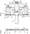
- FIG.5 is a shematic side view for illustrating a shutter driving unit in the drawout type switch gear shown in FIGs.1 and 2, in its non-actuated state
- FIG.6 is a rear view of the shutter driving unit of in FIG.5, as seen from the rear left side
- FIG.7 is a schematic side view for illustrating the shutter driving unit of FIG.5 in its actuated state.
- the parts and components which are the same or equivalent to those used in the previously described prior art switch gear will be denoted with the same or similar reference numerals and the descriptions therefor will be omitted.
- lead conductor-carrying members 11 are supported by an upper angle 12 and a lower angle 13 traversely provided on the base frame 1.
- Each of the lead conductor-carrying members 11 is composed of a pair of left-right (horizontally) symmetrical half bodies 11A and 11B (FIGs.3 and 4).
- Each of the half bodies 11A and 11B has a dowel 14a or 14b for fitting in rectangular openings 12a provided on the upper angle 12, and dowel 15a or 15b for fitting in rectangular openings 13a provided on the lower angle 13.
- each of the half bodies 11A and 11B has on its front face three protrusions with guiding grooves 16a or 16b, and, on its rear face recesses 17a and 17b which, when combined together, each forms the openings 17 for passing the lead conductors therethrough.
- insertion spaces 18 between each of the lead conductor-carrying members 11.
- Three fixed shutter blades 19 are having such sizes as to be inserted along the guiding grooves 16a and 16b downward and held on the front faces of the lead conductor-carrying members 11.
- Each of the fixed shutter blades 19 has two opening 19a for accommodating the lead conductors, and is prevented from its upward extracting movement by one of protrusions 20 provided on the upper angle 12.
- Each of the insertion spaces 18 permits the insertion of one of the shutter driving sub-units 21, and, in its accommodated state, is prevented from its forward extracting movement.
- Each of the shutter driving units 21 comprises a housing 22, a rod 23 which can project forward from the housing 22, a pair of compression springs 24 for giving an invariable projecting tendency on the rod 23, a pair of levers 25 each of which is shaped to be symmetrical with respect to the center line of the rod 23 and pivotally mounted on the housing 22, a pair of movable shutter blades 27 and a pair of return springs 26 for urging the levers 25 in the direction of closing the safety shutter device.
- Each of the movable shutter blades 27 is located between the front face of the lead conductor-carrying member 11 and one of the fixed shutter blades 19, and is vertically movable by one of the levers 25.
- Each of the levers 25 has an arm having a cam profile and engaging with the root part of the rod 23 and another arm engaging at its tip with one of the opening 28 provided on the movable shutter blade 27.
- the lead conductor-carrying member 11 is fixed on the base frame 1 by combining each of the half bodies 11A and 11B together and fitting it in between the upper angle 12 having the rectangular openings 12a and the lower angle 13 having the rectangular openings 13a, as shown by FIG. 3. Then the insertions spaces 18 are formed between the lead conductor-carrying members 11. In the state shown in FIG.3, when the shutter driving units 21 are inserted into these insertion spaces 18 and the fixed shutter blades 19 are inserted into the front face of the lead conductor-carrying members 11 between both guiding grooves 16a and 16b by pushing them 21 downward, the fixed shutter blades 19 are retained there by the protrusions 20 as shown by FIGs.1 and 2.
- the safety shutter device of the present invention can be installed in the switch gear without any need of tools.
- the movable shutter blades 27 are in their closed position because the rod 23 are projected and the levers 25 are urged by the return springs 26 to close the movable shutter blades 27 as shown by FIGs.2 and 5.
- the circuit breaker 2 is moved to its connected position and pushes the projected rods 23, the levers 25 are rotated against the urging by the return springs 26 thereby to open the movable shutter blades 27 and bring the connected state of the circuit breaker 2 as shown by FIGs.1 and 7.
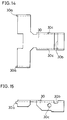
- FIG.8 is a schematic side view for illustrating the shutter driving unit.
- FIG.9 is a rear view the shutter driving unit shown in FIG.8, as viewed the latter from the left side.
- FIG.10 is a schematic side view for illustrating the shutter driving unit of FIG.8 in its actuated state.
- FIG.11 is a schematic perspective view of the rods in the shutter driving unit shown in FIG.8.
- FIG.12 is a shematic perspective view of the rods in the shutter driving sub-unit of FIG.8 with a man's hand, for illustrating the manner of actuating the rods.
- the parts and components which are the same or equivalent to those used in the forgoing embodiment will be denoted with the same or similar reference numerals, and the descriptions therefor will be omitted.
- a rod 29 for the shutter driving unit 21 is composed of a pair of vertically symmetrical upper half rod 29A and lower half rod 29B, each of which has a stopper 29a or 29b on its confronting face.
- One of the stoppers 29a or 29b can engage with one of the root portion of the pair of half rods 29B or 29A as shown by FIG.10.
- the rod 29 When the rod 29 is configured to be divided into the pair of half rod 29A and 29B, only one of the movable shutter blades, for instance, the upper shutter blade 27 can be opened by pushing in only the upper half rod 29A.
- An inspection on one of the circuits of the source side and the load side namely, the inspection on a circuit actually requiring a check, can be performed individually by opening only one of the movable shutter 27, and thereby the safety is further improved. Since, the stopper 29a is engaging with the half rod 29B as shown by FIG.10 when the half rod 29A is pushed, the upper half rod 29A is retained at the pushed-in state, and the upper movable shutter balde 27 is held at its opened position.
- the upper half rod 29A can be released from the engagement with the lower half rod 29B by pulling it from the shutter driving sub-unit 11 in the direction indicated by an arrow shown in FIG.11.
- the rod 29 as the whole can be integrally pushed in or pulled from the shutter driving unit 11 as a combined body of the half rods 29A and 29B together or individually.
- FIG.13 is a perspective view of the safety shutter device of this embodiment, in its locked state.
- FIG.14 is a schematic side view of a lock plate for use in the safety device shown in FIG.13.
- FIG.15 is a schematic plan view of the lock plate shown in FIG.14.
- the parts and components which are the same or equivalent to those used in the forgoing embodiment will be denoted with the same or similar reference numerals and the descriptions therefor will be omitted.
- each of the lock plates 30 has a pair of pawls 30a for receiving and retaining the movable shutter blades 27 in their closed positions, a notch 30b for accommodating the head part of the rod 23 or 29, and an opening 30c for receiving a padlock 31.
Landscapes
- Engineering & Computer Science (AREA)
- Power Engineering (AREA)
- Trip Switchboards (AREA)
- Operating, Guiding And Securing Of Roll- Type Closing Members (AREA)
- Breakers (AREA)
Abstract
Description
- The present invention generally relates to a drawout type switch gear. More particularly, it is concerned with a safety shutter device for such a drawout type switch gear that has a base frame, a circuit breaker movably mounted on said base frame in a manner to be drawn out of or pushed into said base frame.
- One of the prior art safety shutter device for the drawout type switch gear as shown in Japanese Utility Model Examined Publication (Jikko Sho) 61-14,256 is illustrated in FIGs. 16, 17 and 18 of the attached drawings. In those Figures, FIG.16 is a schematic side view of the drawout type switch gear in its state wherein the circuit breaker is drawn out of the base frame, FIG.17 is a schematic side view of the switch gear shown in FIG.16, in such a state that the circuit breaker is on a way to be inserted into the base frame, with its shutter open, and FIG.18 is a schematic side view of the switch gear shown in FIGs. 16 and 17, in the connected state of the circuit breaker.
- In these Figures, the switch gear with the safety shutter device includes: a
base frame 1, thecircuit breaker 2 movably mounted on thebase frame 1 so as to be drawn out of or pushed into thebase frame 1, a pair of frame-side maincircuit lead conductors 3 mounted on thebase frame 1 through aterminal pedestal 4, a pair of breaker-side maincircuit lead conductors 5 mounted on thecircuit breaker 2, afixed shutter blade 6 mounted on thebase frame 1 and having a pair ofopenings 6a for the lead conductors, amovable shutter blade 7 also mounted on thebase frame 1 while permitted of its limited vertical movement with respect to the fixedshutter blade 6 and having a pair ofopenings 7a for the lead conductors, an actuatingpin 8 provided on themovable shutter blade 7, a shutter actuatingplate 9 provided on thecircuit breaker 2 whoseslope 9a can engage with the actuatingpin 8 to effect the limited vertical movement of themovable shutter blade 7, and a pair ofcontact fingers 10 mounted on thebase frame 1 for connecting the bothlead conductors - In the following paragraphs, the operation of the above-mentioned prior art drawout type switch gear combined with the safety shutter device will be described.
- When the
circuit breaker 2 is in its drawn out position, themovable shutter blade 7 is in its lower position and closes the opening 6a of thefixed shutter blade 6 as shown by FIG.16. When thecircuit breaker 2 of the location indicated by FIG.16 is pushed into thebase frame 1, themovable shutter blade 7 is elevated by the actuatingplate 9 to bring an open state of thefixed shutter blade 6 on the way of thecircuit breaker 2 to be inserted into thebase frame 1 shown by FIG.17. Thus the breaker-side maincircuit lead conductors 5 are connected to thecontact fingers 10 through both theopenings - In the above-mentioned safety shutter device, the
shutter blades - The present invention has been made in order to solve the above-mentioned problem, and has, as its object, a provision of a safety shutter device for the drawout type switch gear that has a good workability in assembling, and permits an easy maintenance and inspection. The disclosed safety shutter device can be installed on the drawout type switch gear in a simple operation without using any tool.
- According to the present invention, the drawout type switch gear comprises, a base frame, a circuit breaker which is movably mounted on the base frame in a manner to be drawn out of or pushed into the base frame when transferred between a drawout position and a pushed-in position, (a) pair(s) of breaker-side main circuit lead conductors provided on the circuit breaker and (a) pair(s) of base frame-side main circuit lead conductors provided on the base frame, wherein the breaker-side main circuit lead conductors are arranged to connect to the base frame-side main circuit lead conductors in the pushed-in position through a pair of contact fingers provided on the base frame,
a safety shutter device which is provided on the base frame and including:
at least one lead conductor-carrying member provided on the base frame, leaving at least one insertion space between the lead conductor-carrying members or between the side wall of the base frame and one of the lead conductor-carrying members;
at least one fixed shutter blade provided on the front face of the lead conductor-carrying member and each having a pair of openings for permitting the breaker-side main circuit lead conductors to put therethrough; and
at least one shutter driving unit accommodated in the insertion space and secured there by the fixed shutter blade, which includes; and
a pair of movable shutter blades provided in front of the shutter driving unit, which are permitted of a limited vertical movement by the drawout and poushed-in operation of the circuit breaker and, when the shutter driving unit is accommodated in the insertion space, are located behind the fixed shutter blades to constitute a shutter-closed state for the switch gear in combination with the fixed shutter blades. - In the above-mentioned safety shutter device for drawout type switch gear, each of the shutter driving unit preferably comprises;
a rod which retracts into the shutter driving unit against the urging by a compression spring, upon the push-in operation of the circuit breaker, and
a pair of levers pivotally mounted on the shutter driving unit and engaging with the rod and the movable shutter blades, each of which rotates against the urging by a return spring, upon the retracting movement of the rod and causes one of the movable shutter blade to move, thereby causing the shutter device to open. - In the above-mentioned safety shutter device for drawout type switch gear, each of the shutter driving unit may alternatively comprises;
a pair of rod, each of which individually retracts into the shutter driving unit against the urging by a compression spring upon the push-in operation of the circuit breaker,
a pair of levers which are pivotally mounted on the shutter driving unit and engaging with one of the rods and one of the movable shutter blades, and each of which lever individually rotates against the urging by a return spring upon the retracting movement of the rod and causes one of the movable shutter blades to move, thereby causing the shutter device to partly open, and
a pair of stoppers provided on each of the rods for retaining one of the rods in its retracted position. - The above-mentioned safety shutter device for drawout type switch gear may further comprises;
at least one lock plate having a width sufficient for holding the rod in its extended position, a pair of pawls for receiving the movable shutter blades and holding them not to move, a notch for accommodating the head of the rod, and an opening for a padlock, and
the padlock which can engage with the opening for securing the lock plate in its fixed position on the rod. - As above-described, in accordance with the present invention, the installation of the safety shutter device can be completed simply by inserting the shutter driving unit into the insertion space, securing the unit therein with the fixed shutter blade, and fixing the movable shutter blades on the shutter driving unit. The thus configured safety shutter device has such an advantage that it can be installed without using any tool and that it has a good workability in assembling as well as in its maintenance and inspection.
- While the novel features of the present invention are set fourth particularly in the appended claims, the invention, both as to organization and content, will be better understood and appreciated, along with other objects and features thereof, from the following detailed description taken in conjunction with the attached drawings.
-
- FIG.1 is a schematic side view of the drawout type switch gear equipped with the safety device built in accordance with a first embodiment of the present invention, in its connected state.
- FIG.2 is a schematic side view of the drawout switch gear of FIG.1, in its disconnected state.
- FIG.3 is an exploded perspective view of a shutter device in the drawout type switch gear shown in FIGs.1 and 2.
- FIG.4 is an exploded perspective view of lead conductor carrying parts in the drawout type switch gear shown in FIGs.1 and 2.
- FIG.5 is a schematic side view for illustrating a shutter driving unit in the drawout type switch gear shown in FIGs.1 and 2, in its non-actuated state.
- FIG.6 is a rear view of the shutter driving unit shown in FIG.5, as viewed the latter from the left side.
- FIG.7 is a schematic side view for illustrating the shutter driving unit of FIG.5 in its actuated state.
- FIG.8 is a schematic side view for illustrating the shutter driving unit built in accordance with a second embodiment of the present invention
- FIG.9 is a rear view the shutter driving unit shown in FIG.8, as viewed the latter from the left side.
- FIG.10 is a schematic side view for illustrating the shutter driving unit of FIG.8 in its actuated state.
- FIG.11 is a schematic perspective view of the rods in the shutter driving unit shown in FIG.8.
- FIG.12 is a shematic perspective view of the rods in the shutter driving unit of FIG.8 with a man's hand, for illustrating the manner of actuating the rods.
- FIG.13 is a perspective view of the safety shutter device built in accordance with a third embodiment of the present invention, in its locked state.
- FIG.14 is a schematic side view of a lock plate for use in the safety device shown in FIG.13.
- FIG.15 is a schematic plan view of the lock plate shown in FIG.14.
- FIG.16 is a schematic side view of the prior art drawout type switch gear in its state wherein the circuit breaker is withdrawn from the base frame.
- FIG.17 is a schematic side view of the prior art drawout type switch gear shown in FIG.16, in its state wherein the circuit breaker is in its way to be inserted into the base frame.
- FIG.18 is a schematic side view of the prior art drawout type switch gear shown in FIGs.16 and 17, in its connected state.
- It will be recognized that some or all of the Figures are schematic representations for purposes of illustration and do not necessarily depict the actual relative sizes or locations of the elements shown.
- In the following paragraphs, the present invention will be described in more detail by way of example with reference to the preferred embodiments shown in the attached drawings.
- The first embodiment of the present invention will now be illustrated by referring to FIG.1 through FIG.7 of the drawings. FIG.1 is a schematic side view of the drawout type switch gear equipped with the safety device built in accordance with the first embodiment, in its connected state. FIG.2 is a schematic side view of the drawout switch gear of FIG.1, in its disconnected state. FIG.3 is an exploded perspective view of a shutter unit in the drawout type switch gear shown in FIGs.1 and 2. FIG.4 is an exploded perspective view of lead conductor carrying parts in the drawout type switch gear shown in FIGs.1 and 2. FIG.5 is a shematic side view for illustrating a shutter driving unit in the drawout type switch gear shown in FIGs.1 and 2, in its non-actuated state, FIG.6 is a rear view of the shutter driving unit of in FIG.5, as seen from the rear left side. FIG.7 is a schematic side view for illustrating the shutter driving unit of FIG.5 in its actuated state. In these Figures, the parts and components which are the same or equivalent to those used in the previously described prior art switch gear will be denoted with the same or similar reference numerals and the descriptions therefor will be omitted.
- In these Figures, lead conductor-carrying
members 11 are supported by anupper angle 12 and alower angle 13 traversely provided on thebase frame 1. Each of the lead conductor-carryingmembers 11 is composed of a pair of left-right (horizontally)symmetrical half bodies half bodies dowel rectangular openings 12a provided on theupper angle 12, anddowel rectangular openings 13a provided on thelower angle 13. In addition, each of thehalf bodies grooves openings 17 for passing the lead conductors therethrough. - When the lead conductor-carrying
members 11 are supported by the upper andlower angles insertion spaces 18 between each of the lead conductor-carryingmembers 11. Three fixedshutter blades 19 are having such sizes as to be inserted along the guidinggrooves members 11. Each of the fixedshutter blades 19 has twoopening 19a for accommodating the lead conductors, and is prevented from its upward extracting movement by one ofprotrusions 20 provided on theupper angle 12. Each of theinsertion spaces 18 permits the insertion of one of theshutter driving sub-units 21, and, in its accommodated state, is prevented from its forward extracting movement. This prevention is caused by engagement of the upper and lowerlateral protrusions 21a of theshutter driving unit 21 with one of the inner face of the fixedshutter blades 19. Each of theshutter driving units 21 comprises ahousing 22, arod 23 which can project forward from thehousing 22, a pair of compression springs 24 for giving an invariable projecting tendency on therod 23, a pair oflevers 25 each of which is shaped to be symmetrical with respect to the center line of therod 23 and pivotally mounted on thehousing 22, a pair ofmovable shutter blades 27 and a pair of return springs 26 for urging thelevers 25 in the direction of closing the safety shutter device. Each of themovable shutter blades 27 is located between the front face of the lead conductor-carryingmember 11 and one of the fixedshutter blades 19, and is vertically movable by one of thelevers 25. Each of thelevers 25 has an arm having a cam profile and engaging with the root part of therod 23 and another arm engaging at its tip with one of theopening 28 provided on themovable shutter blade 27. - In the following paragraphs, the installation of the thus configured shutter unit in the drawout type switch gear will be described.
- First, the lead conductor-carrying
member 11 is fixed on thebase frame 1 by combining each of thehalf bodies upper angle 12 having therectangular openings 12a and thelower angle 13 having therectangular openings 13a, as shown by FIG. 3. Then theinsertions spaces 18 are formed between the lead conductor-carryingmembers 11. In the state shown in FIG.3, when theshutter driving units 21 are inserted into theseinsertion spaces 18 and the fixedshutter blades 19 are inserted into the front face of the lead conductor-carryingmembers 11 between both guidinggrooves shutter blades 19 are retained there by theprotrusions 20 as shown by FIGs.1 and 2. In this state, thelateral protrusions 21a of theshutter driving units 21 are engaging with the inner faces of the fixedshutter blades 19 and prevent theshutter driving units 21 from their forward extracting movement. Thus theshutter driving units 21 are retained there, as shown by FIGs. 5 and 7. Before the fixedshutter blades 19 are inserted downward, the tips of thelevers 25 have previously been fit in theopenings 28 of themovable shutter blades 27 located behind the fixedshutter blades 19. - As previously described, the safety shutter device of the present invention can be installed in the switch gear without any need of tools. In the assembled state, when the
circuit breaker 2 is in its drawout position, themovable shutter blades 27 are in their closed position because therod 23 are projected and thelevers 25 are urged by the return springs 26 to close themovable shutter blades 27 as shown by FIGs.2 and 5. On the other hand, when thecircuit breaker 2 is moved to its connected position and pushes the projectedrods 23, thelevers 25 are rotated against the urging by the return springs 26 thereby to open themovable shutter blades 27 and bring the connected state of thecircuit breaker 2 as shown by FIGs.1 and 7. - Another embodiment of the present invention will be described with reference to FIG.8 through FIG.12 of the drawings. FIG.8 is a schematic side view for illustrating the shutter driving unit. FIG.9 is a rear view the shutter driving unit shown in FIG.8, as viewed the latter from the left side. FIG.10 is a schematic side view for illustrating the shutter driving unit of FIG.8 in its actuated state. FIG.11 is a schematic perspective view of the rods in the shutter driving unit shown in FIG.8. And FIG.12 is a shematic perspective view of the rods in the shutter driving sub-unit of FIG.8 with a man's hand, for illustrating the manner of actuating the rods. In these Figures, the parts and components which are the same or equivalent to those used in the forgoing embodiment will be denoted with the same or similar reference numerals, and the descriptions therefor will be omitted.
- In this embodiment, a
rod 29 for theshutter driving unit 21 is composed of a pair of vertically symmetrical upperhalf rod 29A andlower half rod 29B, each of which has astopper stoppers half rods - When the
rod 29 is configured to be divided into the pair ofhalf rod upper shutter blade 27 can be opened by pushing in only theupper half rod 29A. An inspection on one of the circuits of the source side and the load side, namely, the inspection on a circuit actually requiring a check, can be performed individually by opening only one of themovable shutter 27, and thereby the safety is further improved. Since, thestopper 29a is engaging with thehalf rod 29B as shown by FIG.10 when thehalf rod 29A is pushed, theupper half rod 29A is retained at the pushed-in state, and the uppermovable shutter balde 27 is held at its opened position. Theupper half rod 29A can be released from the engagement with thelower half rod 29B by pulling it from the shutter driving sub-unit 11 in the direction indicated by an arrow shown in FIG.11. Therod 29 as the whole can be integrally pushed in or pulled from theshutter driving unit 11 as a combined body of thehalf rods - A further embodiment of the present invention will now be described with reference to FIG.13 through FIG.15 of the drawings. FIG.13 is a perspective view of the safety shutter device of this embodiment, in its locked state. FIG.14 is a schematic side view of a lock plate for use in the safety device shown in FIG.13. FIG.15 is a schematic plan view of the lock plate shown in FIG.14. In these Figures, the parts and components which are the same or equivalent to those used in the forgoing embodiment will be denoted with the same or similar reference numerals and the descriptions therefor will be omitted.
- As shown by FIGs.14 and 15, each of the
lock plates 30 has a pair ofpawls 30a for receiving and retaining themovable shutter blades 27 in their closed positions, anotch 30b for accommodating the head part of therod opening 30c for receiving apadlock 31. - In the drawout state of the
circuit breaker 2 as shown by FIG.2, when thepawls 30a of thelock plate 30 of a flexible metal plate are inserted in the front face of theshutter driving sub-unit 11 beyond the location of the movable shutter blades 27 (the location is indicated by the dotted line in FIG.5). Then, the head of therod 23 is fit in thenotch 30b by means of the flexibility of thelock plate 30, and thepadlock 31 is fixed through theopening 30c for fixing thelock plate 30 to therod 23 as shown by FIG.13. Accordingly the pushing-in operation of therod 23 and the insertion of thecircuit breaker 2 are effectively prevented. Although the present invention has been described in terms of the poresently preferred embodiments,it is to be understood that such disclosure is not to be interpreted as limiting. Various alterations and modifications will no doubt become apparent to those skilled in the art to which the present invention pertains, after having read the above disclosure. Accordingly, it is intended that the appended claims be interpreted as covering all alterations and modifications as fall within the true spirit and scope of the invention.
Claims (4)
- A drawout type switch gear comprising:
a base frame,
a circuit breaker which is movably mounted on said base frame in a manner to be drawn out of or pushed into said base frame when transferred between a drawout position and a pushed-in position,
at least a pair of breaker-side main circuit lead conductors provided on said circuit breaker and corresponding pair of base frame-side main circuit lead conductors provided on said base frame, said breaker-side main circuit lead conductors being arranged to connect to said base frame-side main circuit lead conductors in said pushed-in position through a pair of contact fingers provided on said base frame, and
a safety shutter device which is provided on said base frame and including:
at least one lead conductor-carrying member provided on said base frame, leaving at least one insertion space between said lead conductor-carrying members or between the side wall of said base frame and one of said lead conductor-carrying members,
at least one fixed shutter blade provided on the front face of said lead conductor-carrying member and each having a pair of openings for permitting said breaker-side
main circuit lead conductors to put therethrough, and
at least one shutter driving unit accommodated in said insertion space and secured there by said fixed shutter blade, each of which includes, and
a pair of movable shutter blades provided in front of said shutter driving unit, which are permitted of a limited vertical movement by said drawout and poushed-in operation of said circuit breaker and, when said shutter driving unit is accommodated in said insertion space, are located behind said fixed shutter blades to constitute a shutter-closed state for the switch gear in combination with said fixed shutter blades. - The safety shutter device for drawout type switch gear in accordance with claim 1, wherein each of said shutter driving unit comprising:
a rod which retracts into said shutter driving unit against the urging by a compression spring, upon said push-in operation of said circuit breaker, and
a pair of levers pivotally mounted on said shutter driving unit and engaging with said rod and said movable shutter blades, each of which rotates against the urging by a return spring, upon said retracting movement of said rod and causes one of the movable shutter blades to move, thereby causing the shutter device to open. - The safety shutter device for drawout type switch gear in accordance with claim 1, wherein each of said shutter driving unit comprising:
a pair of rod, each of which individually retracts into said shutter driving unit against the urging by a compression spring upon said push-in operation of said circuit breaker,
a pair of levers which are pivotally mounted on the shutter driving unit and engaging with one of said rods and one of said movable shutter blades, and each of which lever individually rotates against the urging by a return spring upon said retracting movement of said rod and causes one of the movable shutter blades to move, thereby causing the shutter device to partly open, and
a pair of stoppers provided on each of said rods for retaining one of the rods in its retracted position. - The safety shutter device for drawout type switch gear in accordance with claim 2 or 3, further comprising:
at least one lock plate having a width sufficient for holding said rod in its extended position, a pair of pawls for receiving said movable shutter blades and holding them not to move, a notch for accommodating the head of said rod, and an opening for a padlock, and
the padlock which can engage with said opening for securing said lock plate in its fixed position on said rod.
Applications Claiming Priority (2)
| Application Number | Priority Date | Filing Date | Title |
|---|---|---|---|
| JP4172343A JP2755049B2 (en) | 1992-06-30 | 1992-06-30 | Safety shutter device for draw-out circuit breaker |
| JP172343/92 | 1992-06-30 |
Publications (3)
| Publication Number | Publication Date |
|---|---|
| EP0577111A2 true EP0577111A2 (en) | 1994-01-05 |
| EP0577111A3 EP0577111A3 (en) | 1994-07-13 |
| EP0577111B1 EP0577111B1 (en) | 1996-09-18 |
Family
ID=15940153
Family Applications (1)
| Application Number | Title | Priority Date | Filing Date |
|---|---|---|---|
| EP93110470A Expired - Lifetime EP0577111B1 (en) | 1992-06-30 | 1993-06-30 | Safety shutter device for drawout type switch gear |
Country Status (8)
| Country | Link |
|---|---|
| US (1) | US5343355A (en) |
| EP (1) | EP0577111B1 (en) |
| JP (1) | JP2755049B2 (en) |
| KR (1) | KR970004462B1 (en) |
| CN (1) | CN1052580C (en) |
| DE (1) | DE69304818T2 (en) |
| HK (1) | HK1006763A1 (en) |
| SG (1) | SG54272A1 (en) |
Cited By (9)
| Publication number | Priority date | Publication date | Assignee | Title |
|---|---|---|---|---|
| WO1996021960A1 (en) * | 1995-01-10 | 1996-07-18 | Siemens Aktiengesellschaft | Sliding frame with a break contact arrangement |
| WO1998033253A1 (en) * | 1997-01-24 | 1998-07-30 | Siemens Aktiengesellschaft | Plug-in frame with protecting plates for disconnectors |
| SG83765A1 (en) * | 1999-07-14 | 2001-10-16 | Mitsubishi Electric Corp | Switching device |
| WO2002087041A1 (en) * | 2001-04-23 | 2002-10-31 | Siemens Aktiengesellschaft | Protective unit to prevent contact with conductive contacts in a withdrawable rack of a switching device |
| WO2005027288A1 (en) * | 2003-09-11 | 2005-03-24 | Siemens Aktiengesellschaft | Lockable shutter for withdrawable racks of low-voltage power circuit breakers |
| GB2461616A (en) * | 2008-07-09 | 2010-01-13 | Schneider Electric Ltd | Safety device for electrical distribution boards |
| EP2493038A1 (en) * | 2011-02-24 | 2012-08-29 | LSIS Co., Ltd. | Circuit breaker having cradle |
| WO2019134633A1 (en) * | 2018-01-05 | 2019-07-11 | 浙江正泰电器股份有限公司 | Drawer type circuit breaker |
| US11075506B2 (en) * | 2018-02-01 | 2021-07-27 | Eaton Intelligent Power Limited | Maintenance latch for switchgear shutter |
Families Citing this family (44)
| Publication number | Priority date | Publication date | Assignee | Title |
|---|---|---|---|---|
| US5933319A (en) * | 1998-05-29 | 1999-08-03 | Intel Corporation | Electrical panelboard having an enclosure over an exposed terminal of circuit breaker mounted to a panel of the electrical panelboard |
| US6448519B1 (en) * | 2000-03-20 | 2002-09-10 | General Electric Company | Contact system arrangement for plug-in circuit breakers and base |
| US6414839B1 (en) | 2000-09-29 | 2002-07-02 | Siemens Energy & Automation | Shutter mechanism for vertical bus of motor control center |
| KR100463604B1 (en) * | 2002-05-22 | 2004-12-29 | 엘지산전 주식회사 | assembly structure of shutter plate for draw-out type air circuit breaker |
| US8809705B2 (en) * | 2007-12-04 | 2014-08-19 | General Electric Company | Device and method for switching electrical energy |
| US7064641B2 (en) * | 2004-05-18 | 2006-06-20 | Eaton Corporation | Cathedral door shutter assembly |
| US7348505B2 (en) | 2005-12-21 | 2008-03-25 | General Electric Company | Shutter locking system for draw-out circuit breakers and method of assembly thereof |
| JP4584843B2 (en) * | 2006-02-02 | 2010-11-24 | 寺崎電気産業株式会社 | Shutter device for drawer type circuit breaker |
| US8817454B2 (en) | 2006-07-26 | 2014-08-26 | Eaton Corporation | Coordinating installation and connection of a motor control center subunit having moveable line contacts |
| US10973143B2 (en) | 2006-07-26 | 2021-04-06 | Eaton Intelligent Power Limited | Coordinating installation and connection of a motor control center subunit having moveable line contacts |
| US7688572B2 (en) | 2006-07-26 | 2010-03-30 | Eaton Corporation | Motor control center subunit having moveable line contacts and method of manufacture |
| US7790994B2 (en) * | 2006-10-19 | 2010-09-07 | Rockwell Automation Technologies, Inc. | Draw-out power cell disconnect and isolation mechanism with rack-out guide tray |
| US7440259B1 (en) * | 2007-06-14 | 2008-10-21 | Siemens Aktiengesellschaft | Closure device for a withdrawable rack |
| DE102007054295A1 (en) | 2007-11-09 | 2009-05-14 | Siemens Ag | Protection device against touching electrical conductors in a power distribution unit |
| DE102007055047B4 (en) * | 2007-11-15 | 2021-10-14 | Siemens Aktiengesellschaft | Locking device for a slide-in frame, slide-in frame, actuating element and locking element |
| DE102008020753A1 (en) | 2008-04-18 | 2009-10-22 | Siemens Aktiengesellschaft | Protection device against touching electrical conductors in a power distribution unit |
| US8638561B2 (en) * | 2009-11-06 | 2014-01-28 | Rockwell Automation Technologies, Inc. | Motor control center unit withdraw with door closed |
| EP2325962A1 (en) * | 2009-11-23 | 2011-05-25 | ABB Technology AG | Partitioning device for MV cubicles. |
| CN102237651B (en) * | 2010-04-27 | 2016-08-10 | 上海电科电器科技有限公司 | The retaining device of open frame circuit breaker |
| JP5618806B2 (en) * | 2010-12-14 | 2014-11-05 | 三菱電機株式会社 | Shutter device for switchboard |
| US8366460B2 (en) * | 2011-01-31 | 2013-02-05 | General Electric Company | Withdrawable circuit breaker shutter systems |
| KR101119744B1 (en) * | 2011-02-24 | 2012-03-22 | 엘에스산전 주식회사 | Circuit breaker with earthing member locking unit |
| US9299522B2 (en) * | 2012-09-28 | 2016-03-29 | General Electric Company | Shutter locking mechanism for circuit breaker assembly |
| US8917494B2 (en) * | 2012-10-05 | 2014-12-23 | Siemens Industry, Inc. | Dual action shutter for drawout circuit breaker |
| US9129760B2 (en) * | 2013-01-07 | 2015-09-08 | General Electric Company | Shutter system for a switchgear compartment and method of manipulating a shutter system |
| US9350144B2 (en) | 2013-01-31 | 2016-05-24 | American Mine Research, Inc. | Removable contactor drawer |
| CN105027369B (en) * | 2013-03-14 | 2017-04-12 | 施耐德电气美国股份有限公司 | Independent shutter system for rack-in breakers |
| US9711954B2 (en) | 2013-09-30 | 2017-07-18 | Schneider Electric USA, Inc. | Snap-in shutter system for rack out circuit breakers |
| KR101659327B1 (en) * | 2014-02-26 | 2016-09-30 | 윤여관 | Shutter Barrier for Distributing Board With Auto Locking Function |
| US9312668B2 (en) * | 2014-06-20 | 2016-04-12 | Schneider Electric USA, Inc. | Arc resistant shutters |
| US9748024B2 (en) * | 2014-06-20 | 2017-08-29 | Schneider Electric USA, Inc. | Passive arc control with sequestered phases in a vertical bus system of a motor control center |
| US9531169B2 (en) | 2014-06-30 | 2016-12-27 | Eaton Corporation | Motor control center units with retractable stabs and interlocks using portal shutters |
| US9451718B2 (en) | 2014-06-30 | 2016-09-20 | Eaton Corporation | Telescoping panels suitable for motor control center units and related motor control centers |
| US9396889B1 (en) * | 2015-04-03 | 2016-07-19 | Eaton Corporation | Electrical switching apparatus and secondary disconnect assembly with cradle assembly alignment and positioning features therefor |
| US9336977B1 (en) * | 2015-04-03 | 2016-05-10 | Eaton Corporation | Electrical switching apparatus and secondary disconnect assembly with terminal retention and correction features therefor |
| US10186847B2 (en) | 2016-11-21 | 2019-01-22 | Eaton Intelligent Power Limited | Motor control center (MCC) units with slidable shutters |
| US10211606B2 (en) | 2016-11-29 | 2019-02-19 | Eaton Intelligent Power Limited | Motor control center units with multi-purpose shutter cams and related units |
| EP3627640B1 (en) * | 2017-05-16 | 2021-11-17 | Mitsubishi Electric Corporation | Drawer-type circuit breaker |
| WO2019116498A1 (en) | 2017-12-14 | 2019-06-20 | 三菱電機株式会社 | Drawer-type breaker |
| US10742004B2 (en) | 2017-12-20 | 2020-08-11 | Eaton Intelligent Power Limited | Motor control center (MCC) units with retractable power connector and interlocks including a power connector position interlock |
| WO2019171500A1 (en) * | 2018-03-07 | 2019-09-12 | 三菱電機株式会社 | Draw-out type circuit breaker |
| US10439371B1 (en) | 2018-06-22 | 2019-10-08 | Schneider Electric USA, Inc. | Snapped in rotating arc housing assembly for safety switch |
| CA3073017A1 (en) | 2019-02-22 | 2020-08-22 | Eaton Intelligent Power Limited | Motor control center (mcc) units with dual disconnect switches, dual operator handles, retractable power connector and interlocks |
| US20230344203A1 (en) * | 2022-04-22 | 2023-10-26 | Abb Schweiz Ag | Systems and methods for transferring heat generated in an electrical enclosure |
Citations (4)
| Publication number | Priority date | Publication date | Assignee | Title |
|---|---|---|---|---|
| GB807952A (en) * | 1955-05-13 | 1959-01-28 | English Electric Co Ltd | Improvements in and relating to withdrawable electric switchgear |
| JPS5431539A (en) * | 1977-08-15 | 1979-03-08 | Toshiba Corp | Folding shutter device |
| JPS54121943A (en) * | 1978-03-14 | 1979-09-21 | Toshiba Corp | Closed switchboard |
| SU858157A1 (en) * | 1979-07-23 | 1981-08-23 | Предприятие П/Я А-1184 | Unitized distributing device cabinet |
Family Cites Families (4)
| Publication number | Priority date | Publication date | Assignee | Title |
|---|---|---|---|---|
| US4285026A (en) * | 1979-08-13 | 1981-08-18 | Gould Inc. | Parallel plane shutter for LK breaker |
| JPS596563A (en) * | 1982-07-05 | 1984-01-13 | Nec Corp | Integrated circuit device |
| JPS6439281A (en) * | 1987-07-31 | 1989-02-09 | Noritz Corp | Rotation controller for dc motor |
| JPH0638685B2 (en) * | 1987-09-24 | 1994-05-18 | 株式会社戸上電機製作所 | Closed switchboard |
-
1992
- 1992-06-30 JP JP4172343A patent/JP2755049B2/en not_active Expired - Fee Related
-
1993
- 1993-06-19 KR KR1019930011253A patent/KR970004462B1/en not_active IP Right Cessation
- 1993-06-23 CN CN93108726A patent/CN1052580C/en not_active Expired - Lifetime
- 1993-06-24 US US08/080,770 patent/US5343355A/en not_active Expired - Lifetime
- 1993-06-30 DE DE69304818T patent/DE69304818T2/en not_active Expired - Lifetime
- 1993-06-30 EP EP93110470A patent/EP0577111B1/en not_active Expired - Lifetime
-
1996
- 1996-03-29 SG SG1996006907A patent/SG54272A1/en unknown
-
1998
- 1998-06-22 HK HK98105842A patent/HK1006763A1/en not_active IP Right Cessation
Patent Citations (4)
| Publication number | Priority date | Publication date | Assignee | Title |
|---|---|---|---|---|
| GB807952A (en) * | 1955-05-13 | 1959-01-28 | English Electric Co Ltd | Improvements in and relating to withdrawable electric switchgear |
| JPS5431539A (en) * | 1977-08-15 | 1979-03-08 | Toshiba Corp | Folding shutter device |
| JPS54121943A (en) * | 1978-03-14 | 1979-09-21 | Toshiba Corp | Closed switchboard |
| SU858157A1 (en) * | 1979-07-23 | 1981-08-23 | Предприятие П/Я А-1184 | Unitized distributing device cabinet |
Non-Patent Citations (3)
| Title |
|---|
| DATABASE WPI Week 1304, Derwent Publications Ltd., London, GB; AN 82-H16667E & SU-A-858 157 (I. A. GERVITS ET AL.) 23 August 1981 * |
| PATENT ABSTRACTS OF JAPAN vol. 3, no. 143 (E-154) 27 November 1979 & JP-A-54 121 943 (TOSHIBA CORP.) 21 September 1979 * |
| PATENT ABSTRACTS OF JAPAN vol. 3, no. 52 (E-108) 7 May 1979 & JP-A-54 031 539 (TOSHIBA CORP.) 8 March 1979 * |
Cited By (16)
| Publication number | Priority date | Publication date | Assignee | Title |
|---|---|---|---|---|
| DE19501928A1 (en) * | 1995-01-10 | 1996-07-25 | Siemens Ag | Slide-in frame with an isolating contact arrangement |
| US6031191A (en) * | 1995-01-10 | 2000-02-29 | Siemens Aktiengesellschaft | Sliding frame with a break contact arrangement |
| WO1996021960A1 (en) * | 1995-01-10 | 1996-07-18 | Siemens Aktiengesellschaft | Sliding frame with a break contact arrangement |
| WO1998033253A1 (en) * | 1997-01-24 | 1998-07-30 | Siemens Aktiengesellschaft | Plug-in frame with protecting plates for disconnectors |
| SG83765A1 (en) * | 1999-07-14 | 2001-10-16 | Mitsubishi Electric Corp | Switching device |
| WO2002087041A1 (en) * | 2001-04-23 | 2002-10-31 | Siemens Aktiengesellschaft | Protective unit to prevent contact with conductive contacts in a withdrawable rack of a switching device |
| US7903393B2 (en) | 2003-09-11 | 2011-03-08 | Siemens Aktiengesellschaft | Lockable shutter for withdrawable racks of low-voltage power circuit breakers |
| WO2005027288A1 (en) * | 2003-09-11 | 2005-03-24 | Siemens Aktiengesellschaft | Lockable shutter for withdrawable racks of low-voltage power circuit breakers |
| DE10342596B3 (en) * | 2003-09-11 | 2005-05-12 | Siemens Ag | Lockable shutter for slide-in frame of low-voltage circuit breakers |
| GB2461616A (en) * | 2008-07-09 | 2010-01-13 | Schneider Electric Ltd | Safety device for electrical distribution boards |
| GB2461616B (en) * | 2008-07-09 | 2012-06-20 | Schneider Electric Ltd | Safety device for electrical distribution boards |
| EP2493038A1 (en) * | 2011-02-24 | 2012-08-29 | LSIS Co., Ltd. | Circuit breaker having cradle |
| US8604368B2 (en) | 2011-02-24 | 2013-12-10 | Lsis Co., Ltd. | Circuit breaker having cradle with a shutter safety device |
| WO2019134633A1 (en) * | 2018-01-05 | 2019-07-11 | 浙江正泰电器股份有限公司 | Drawer type circuit breaker |
| US11158468B2 (en) | 2018-01-05 | 2021-10-26 | Zhejiang Chint Electrics Co., Ltd. | Drawer type circuit breaker |
| US11075506B2 (en) * | 2018-02-01 | 2021-07-27 | Eaton Intelligent Power Limited | Maintenance latch for switchgear shutter |
Also Published As
| Publication number | Publication date |
|---|---|
| DE69304818T2 (en) | 1997-01-30 |
| HK1006763A1 (en) | 1999-03-12 |
| EP0577111A3 (en) | 1994-07-13 |
| SG54272A1 (en) | 1998-11-16 |
| KR940001503A (en) | 1994-01-11 |
| DE69304818D1 (en) | 1996-10-24 |
| US5343355A (en) | 1994-08-30 |
| CN1052580C (en) | 2000-05-17 |
| CN1090095A (en) | 1994-07-27 |
| JPH0622418A (en) | 1994-01-28 |
| JP2755049B2 (en) | 1998-05-20 |
| EP0577111B1 (en) | 1996-09-18 |
| KR970004462B1 (en) | 1997-03-27 |
Similar Documents
| Publication | Publication Date | Title |
|---|---|---|
| US5343355A (en) | Safety shutter device for drawout type switch gear | |
| US7322840B2 (en) | Package with locking mechanism and optical transceiver | |
| CN103380553A (en) | Withdrawable unit for an electric switching device | |
| US5688134A (en) | IC card connector apparatus | |
| EP0776070A2 (en) | Connecting apparatus | |
| US4443676A (en) | Interchangeable shield arrangement for a circuit breaker compartment | |
| DE102008018271A1 (en) | Plug-connection | |
| US6493236B1 (en) | Electronic equipment | |
| US20070059985A1 (en) | Card connector with anti-mismating device | |
| EP0877978A2 (en) | Slide-in rack for a hard-disk drive with a "hot-replace" capability | |
| JP2019515627A (en) | Panel for receiving a drawer-type device | |
| CN217388021U (en) | Combined hand pulling mechanism | |
| CN220731424U (en) | Anti-touch structure for plug-in circuit breaker and plug-in circuit breaker | |
| US4646263A (en) | Reading and/or writing apparatus including a removable memory-containing cassette | |
| CN221651426U (en) | Circuit breaker | |
| CN211605055U (en) | Locking structure of distribution electrical apparatus | |
| JP3355686B2 (en) | Switch operation mechanism | |
| CN111200254B (en) | Switch cabinet and secondary interlocking device thereof | |
| JPS6237375Y2 (en) | ||
| KR200205038Y1 (en) | Opertional cam apparatus of push button switch | |
| JPH0323770Y2 (en) | ||
| JPH038008Y2 (en) | ||
| CN114865519A (en) | Drawer slide locking means and have its circuit breaker | |
| JPH01198205A (en) | Display device for switchboard | |
| JPH0442709A (en) | Drawer type circuit breaker |
Legal Events
| Date | Code | Title | Description |
|---|---|---|---|
| PUAI | Public reference made under article 153(3) epc to a published international application that has entered the european phase |
Free format text: ORIGINAL CODE: 0009012 |
|
| AK | Designated contracting states |
Kind code of ref document: A2 Designated state(s): DE FR GB IT NL |
|
| PUAL | Search report despatched |
Free format text: ORIGINAL CODE: 0009013 |
|
| AK | Designated contracting states |
Kind code of ref document: A3 Designated state(s): DE FR GB IT NL |
|
| 17P | Request for examination filed |
Effective date: 19940728 |
|
| 17Q | First examination report despatched |
Effective date: 19950412 |
|
| GRAH | Despatch of communication of intention to grant a patent |
Free format text: ORIGINAL CODE: EPIDOS IGRA |
|
| GRAA | (expected) grant |
Free format text: ORIGINAL CODE: 0009210 |
|
| GRAH | Despatch of communication of intention to grant a patent |
Free format text: ORIGINAL CODE: EPIDOS IGRA |
|
| AK | Designated contracting states |
Kind code of ref document: B1 Designated state(s): DE FR GB IT NL |
|
| REF | Corresponds to: |
Ref document number: 69304818 Country of ref document: DE Date of ref document: 19961024 |
|
| ITF | It: translation for a ep patent filed | ||
| ET | Fr: translation filed | ||
| PLBE | No opposition filed within time limit |
Free format text: ORIGINAL CODE: 0009261 |
|
| STAA | Information on the status of an ep patent application or granted ep patent |
Free format text: STATUS: NO OPPOSITION FILED WITHIN TIME LIMIT |
|
| 26N | No opposition filed | ||
| ITPR | It: changes in ownership of a european patent |
Owner name: OFFERTA DI LICENZA AL PUBBLICO;AL PUBBLICO |
|
| REG | Reference to a national code |
Ref country code: GB Ref legal event code: 746 Effective date: 19990519 |
|
| REG | Reference to a national code |
Ref country code: FR Ref legal event code: D6 |
|
| REG | Reference to a national code |
Ref country code: GB Ref legal event code: IF02 |
|
| PGFP | Annual fee paid to national office [announced via postgrant information from national office to epo] |
Ref country code: NL Payment date: 20020628 Year of fee payment: 10 |
|
| PGFP | Annual fee paid to national office [announced via postgrant information from national office to epo] |
Ref country code: GB Payment date: 20030625 Year of fee payment: 11 |
|
| PG25 | Lapsed in a contracting state [announced via postgrant information from national office to epo] |
Ref country code: NL Free format text: LAPSE BECAUSE OF NON-PAYMENT OF DUE FEES Effective date: 20040101 |
|
| NLV4 | Nl: lapsed or anulled due to non-payment of the annual fee |
Effective date: 20040101 |
|
| PG25 | Lapsed in a contracting state [announced via postgrant information from national office to epo] |
Ref country code: GB Free format text: LAPSE BECAUSE OF NON-PAYMENT OF DUE FEES Effective date: 20040630 |
|
| GBPC | Gb: european patent ceased through non-payment of renewal fee |
Effective date: 20040630 |
|
| PG25 | Lapsed in a contracting state [announced via postgrant information from national office to epo] |
Ref country code: IT Free format text: LAPSE BECAUSE OF NON-PAYMENT OF DUE FEES;WARNING: LAPSES OF ITALIAN PATENTS WITH EFFECTIVE DATE BEFORE 2007 MAY HAVE OCCURRED AT ANY TIME BEFORE 2007. THE CORRECT EFFECTIVE DATE MAY BE DIFFERENT FROM THE ONE RECORDED. Effective date: 20050630 |
|
| PGFP | Annual fee paid to national office [announced via postgrant information from national office to epo] |
Ref country code: FR Payment date: 20110621 Year of fee payment: 19 |
|
| PGFP | Annual fee paid to national office [announced via postgrant information from national office to epo] |
Ref country code: DE Payment date: 20110622 Year of fee payment: 19 |
|
| REG | Reference to a national code |
Ref country code: FR Ref legal event code: ST Effective date: 20130228 |
|
| REG | Reference to a national code |
Ref country code: DE Ref legal event code: R119 Ref document number: 69304818 Country of ref document: DE Effective date: 20130101 |
|
| PG25 | Lapsed in a contracting state [announced via postgrant information from national office to epo] |
Ref country code: DE Free format text: LAPSE BECAUSE OF NON-PAYMENT OF DUE FEES Effective date: 20130101 Ref country code: FR Free format text: LAPSE BECAUSE OF NON-PAYMENT OF DUE FEES Effective date: 20120702 |