EP0576593B1 - Fluid dispensing system - Google Patents
Fluid dispensing system Download PDFInfo
- Publication number
- EP0576593B1 EP0576593B1 EP92909533A EP92909533A EP0576593B1 EP 0576593 B1 EP0576593 B1 EP 0576593B1 EP 92909533 A EP92909533 A EP 92909533A EP 92909533 A EP92909533 A EP 92909533A EP 0576593 B1 EP0576593 B1 EP 0576593B1
- Authority
- EP
- European Patent Office
- Prior art keywords
- sealant
- needle valve
- solenoid
- predetermined
- housing portion
- Prior art date
- Legal status (The legal status is an assumption and is not a legal conclusion. Google has not performed a legal analysis and makes no representation as to the accuracy of the status listed.)
- Expired - Lifetime
Links
Images








Classifications
-
- B—PERFORMING OPERATIONS; TRANSPORTING
- B05—SPRAYING OR ATOMISING IN GENERAL; APPLYING FLUENT MATERIALS TO SURFACES, IN GENERAL
- B05C—APPARATUS FOR APPLYING FLUENT MATERIALS TO SURFACES, IN GENERAL
- B05C13/00—Means for manipulating or holding work, e.g. for separate articles
- B05C13/02—Means for manipulating or holding work, e.g. for separate articles for particular articles
- B05C13/025—Means for manipulating or holding work, e.g. for separate articles for particular articles relatively small cylindrical objects, e.g. cans, bottles
-
- B—PERFORMING OPERATIONS; TRANSPORTING
- B05—SPRAYING OR ATOMISING IN GENERAL; APPLYING FLUENT MATERIALS TO SURFACES, IN GENERAL
- B05C—APPARATUS FOR APPLYING FLUENT MATERIALS TO SURFACES, IN GENERAL
- B05C5/00—Apparatus in which liquid or other fluent material is projected, poured or allowed to flow on to the surface of the work
- B05C5/02—Apparatus in which liquid or other fluent material is projected, poured or allowed to flow on to the surface of the work the liquid or other fluent material being discharged through an outlet orifice by pressure, e.g. from an outlet device in contact or almost in contact, with the work
- B05C5/0208—Apparatus in which liquid or other fluent material is projected, poured or allowed to flow on to the surface of the work the liquid or other fluent material being discharged through an outlet orifice by pressure, e.g. from an outlet device in contact or almost in contact, with the work for applying liquid or other fluent material to separate articles
- B05C5/0212—Apparatus in which liquid or other fluent material is projected, poured or allowed to flow on to the surface of the work the liquid or other fluent material being discharged through an outlet orifice by pressure, e.g. from an outlet device in contact or almost in contact, with the work for applying liquid or other fluent material to separate articles only at particular parts of the articles
- B05C5/0216—Apparatus in which liquid or other fluent material is projected, poured or allowed to flow on to the surface of the work the liquid or other fluent material being discharged through an outlet orifice by pressure, e.g. from an outlet device in contact or almost in contact, with the work for applying liquid or other fluent material to separate articles only at particular parts of the articles by relative movement of article and outlet according to a predetermined path
-
- B—PERFORMING OPERATIONS; TRANSPORTING
- B05—SPRAYING OR ATOMISING IN GENERAL; APPLYING FLUENT MATERIALS TO SURFACES, IN GENERAL
- B05C—APPARATUS FOR APPLYING FLUENT MATERIALS TO SURFACES, IN GENERAL
- B05C5/00—Apparatus in which liquid or other fluent material is projected, poured or allowed to flow on to the surface of the work
- B05C5/02—Apparatus in which liquid or other fluent material is projected, poured or allowed to flow on to the surface of the work the liquid or other fluent material being discharged through an outlet orifice by pressure, e.g. from an outlet device in contact or almost in contact, with the work
- B05C5/0208—Apparatus in which liquid or other fluent material is projected, poured or allowed to flow on to the surface of the work the liquid or other fluent material being discharged through an outlet orifice by pressure, e.g. from an outlet device in contact or almost in contact, with the work for applying liquid or other fluent material to separate articles
- B05C5/0212—Apparatus in which liquid or other fluent material is projected, poured or allowed to flow on to the surface of the work the liquid or other fluent material being discharged through an outlet orifice by pressure, e.g. from an outlet device in contact or almost in contact, with the work for applying liquid or other fluent material to separate articles only at particular parts of the articles
- B05C5/0216—Apparatus in which liquid or other fluent material is projected, poured or allowed to flow on to the surface of the work the liquid or other fluent material being discharged through an outlet orifice by pressure, e.g. from an outlet device in contact or almost in contact, with the work for applying liquid or other fluent material to separate articles only at particular parts of the articles by relative movement of article and outlet according to a predetermined path
- B05C5/022—Apparatus in which liquid or other fluent material is projected, poured or allowed to flow on to the surface of the work the liquid or other fluent material being discharged through an outlet orifice by pressure, e.g. from an outlet device in contact or almost in contact, with the work for applying liquid or other fluent material to separate articles only at particular parts of the articles by relative movement of article and outlet according to a predetermined path the outlet being fixed during operation
-
- B—PERFORMING OPERATIONS; TRANSPORTING
- B05—SPRAYING OR ATOMISING IN GENERAL; APPLYING FLUENT MATERIALS TO SURFACES, IN GENERAL
- B05C—APPARATUS FOR APPLYING FLUENT MATERIALS TO SURFACES, IN GENERAL
- B05C5/00—Apparatus in which liquid or other fluent material is projected, poured or allowed to flow on to the surface of the work
- B05C5/02—Apparatus in which liquid or other fluent material is projected, poured or allowed to flow on to the surface of the work the liquid or other fluent material being discharged through an outlet orifice by pressure, e.g. from an outlet device in contact or almost in contact, with the work
- B05C5/0225—Apparatus in which liquid or other fluent material is projected, poured or allowed to flow on to the surface of the work the liquid or other fluent material being discharged through an outlet orifice by pressure, e.g. from an outlet device in contact or almost in contact, with the work characterised by flow controlling means, e.g. valves, located proximate the outlet
-
- B—PERFORMING OPERATIONS; TRANSPORTING
- B29—WORKING OF PLASTICS; WORKING OF SUBSTANCES IN A PLASTIC STATE IN GENERAL
- B29C—SHAPING OR JOINING OF PLASTICS; SHAPING OF MATERIAL IN A PLASTIC STATE, NOT OTHERWISE PROVIDED FOR; AFTER-TREATMENT OF THE SHAPED PRODUCTS, e.g. REPAIRING
- B29C31/00—Handling, e.g. feeding of the material to be shaped, storage of plastics material before moulding; Automation, i.e. automated handling lines in plastics processing plants, e.g. using manipulators or robots
- B29C31/04—Feeding of the material to be moulded, e.g. into a mould cavity
- B29C31/042—Feeding of the material to be moulded, e.g. into a mould cavity using dispensing heads, e.g. extruders, placed over or apart from the moulds
- B29C31/047—Feeding of the material to be moulded, e.g. into a mould cavity using dispensing heads, e.g. extruders, placed over or apart from the moulds combined with moving moulds
-
- B—PERFORMING OPERATIONS; TRANSPORTING
- B29—WORKING OF PLASTICS; WORKING OF SUBSTANCES IN A PLASTIC STATE IN GENERAL
- B29L—INDEXING SCHEME ASSOCIATED WITH SUBCLASS B29C, RELATING TO PARTICULAR ARTICLES
- B29L2031/00—Other particular articles
- B29L2031/56—Stoppers or lids for bottles, jars, or the like, e.g. closures
- B29L2031/565—Stoppers or lids for bottles, jars, or the like, e.g. closures for containers
-
- Y—GENERAL TAGGING OF NEW TECHNOLOGICAL DEVELOPMENTS; GENERAL TAGGING OF CROSS-SECTIONAL TECHNOLOGIES SPANNING OVER SEVERAL SECTIONS OF THE IPC; TECHNICAL SUBJECTS COVERED BY FORMER USPC CROSS-REFERENCE ART COLLECTIONS [XRACs] AND DIGESTS
- Y10—TECHNICAL SUBJECTS COVERED BY FORMER USPC
- Y10S—TECHNICAL SUBJECTS COVERED BY FORMER USPC CROSS-REFERENCE ART COLLECTIONS [XRACs] AND DIGESTS
- Y10S251/00—Valves and valve actuation
- Y10S251/903—Needle valves
Definitions
- This invention relates generally to a system for dispensing fluids, and more particularly to a sealant delivery system and apparatus for application of a sealant compound material to container lids and closures of the type disclosed in United States patent No. 4,262,629 and No. 4,840,138.
- the apparatus of U.S. patents No. 4,262,629 and No. 4,840,138 comprises a rotary can lid feed mechanism having a series of pockets which are advanced through a downstacker area to laterally shift each lowermost lid in succession of the stack of lids along an arcuate guide path into each of a series of shallow recesses formed in a rotary chuck table.
- the rotary chuck table has a series of lift chucks disposed in normally lowered position beneath the recesses, and a rotary drive is operative to synchronously rotate the table and lift chucks at a predetermined rate of speed.
- a cam member located in the path of travel of the lift chucks is operative to advance each lift chuck in succession when it is received at a first station between a normally lowered position and a raised position through a distance corresponding to two stations, after which the lid is lowered as it is advanced to a third station and discharged into a collection area. The empty recess then continues through a distance corresponding to three more stations before it picks up another can lid.
- An upper sealant gun assembly includes a spring-loaded chuck aligned with each recess to as to be engageable with each lid as it is raised by the lift chuck to activate an associated sealant gun in response to such engagement.
- the sealant is discharged from the gun as the can lid is caused to rotate about its own axis by rotation of the lift chuck through the first two stations so as to uniformly deposit the lining material into the groove of each can lid in succession.
- the can lid is lowered by the lift chuck, then disengaged so as to permit the can lid to be discharged from the table preferably by the rotary speed of rotation of the table into a discharge or collection area.
- Feed interrupt mechanism is provided for interrupting advancement of the can lids from the downstacker area in passing in the event of misalignment of a lid; also, an interrupt mechanism is provided in association with the sealant gun to interrupt delivery of sealant in the event that the can lid is not properly aligned with respect to a recess on the chuck table.
- both interrupt mechanisms are controlled by a common sensor in the rotary feed mechanism; however, a separate sensor is provided on the upper chuck assembly to interrupt supply of sealant. Apparatus of this type has been successfully employed with sealant material made from a non-abrasive, non-corrosive solvent base compound which does not present any significant problems in the sealant delivery system.
- U.S. patent No. 4,840,138 provides a sealant dispensing system for use with a conventional rotary-type sealant-applying machine wherein a plurality of circumferentially spaced sealant supply hose means connect a sealant supply means to a plurality of circumferentially spaced sealant dispensing head means which rotate about a central axis of rotation.
- the sealant supply means is located in coaxial relationship with the central axis of rotation and rotates thereabout and comprises an elongated vertical rotatable supply chamber means in which a supply of sealant is maintained under pressure by a supply of compressed air for delivery to the sealant dispensing head means through the supply hose means.
- a spindle means is attached to the supply chamber means for rotation therewith and extends into a non-rotatable support housing with bearing means mounted therebetween.
- the support housing means and the spindle means have coaxial aligned central passages which are coaxial with the central axis of rotation.
- Sealing means are mounted between the spindle means and the support housing means to prevent escape of air from the air passage means. Sealant is delivered to the supply chamber means through a non-rotatable central tubular passage means mounted in the housing and spindle passage means in coaxial alignment with the central axis of rotation. Air is delivered to the supply chamber means through an annular passage means circumjacent the tubular passage means.
- Electrical sensing means are provided to monitor the amount of sealant in the supply chamber means and to cause additional amounts of sealant to be automatically delivered to the supply chamber when a lower chamber level of sealant is detected and to terminate delivery when an upper maximum sealant level is reached.
- the sensing means are activated by contact with the conductive water-base sealant compound.
- the construction and arrangement is such that the sealant does not contact any part of the spindle means nor, the support housing means nor the bearing and sealing means associated therewith.
- U.S. Patent No. 4,339,482 discloses dispensing material with a solenoid actuated dispensing device including a solenoid value having a main body with a valve seat body.
- the main body contains an axially movable valve stem needle which is spring biased closed against an outlet opening when a separately housed actuating solenoid coil, coupled to the valve stem needle is de-energized. Adjustment in the flow gap thorough the outlet opening is manually performed by rotating a solenoid assembly relative to the main body to cause the main body to move axially towards or away from the solenoid assembly.
- U.S. Patent No. 5,133,033 discloses an electrically controlled valve apparatus for dispensing viscous plastic to form a sealing ring around the underside of bottle caps.
- the valve apparatus provides for a flow gap adjustment by way of a manual turn screw arrangement.
- Rotation of a knob, attached to a threaded shaft causes a coil supporting body to move up or down relative to a main body member. Since the upper coil member is attached to the coil supporting body, rotation of the knob and the threaded shaft causes corresponding up and down movement of the upper coil member to provide adjustment of the amount the needle valve may open.
- U.S. Patent No. 3,412,971 discloses a flow gap adjustment by way of a manual turn screw arrangement. Rotation of a knob attached to a threaded shaft, causes a coil supporting body to move up or down relative to the main body member. As the upper coil member is attached to the coil supporting body, rotation of the knob and the threaded shaft causes up and down movement of the upper coil member. The up and down movement of the upper coil member provides an adjustment in the distance the needle valve may open when the coil is actuated.
- U.S. Patent No. 4,437,488 discloses dispensing a plastic material with a solenoid actuated dispensing device including a solenoid valve with a main body.
- the main body includes a valve seat body containing an axially movable valve stem needle which is spring biased closed against an outlet opening.
- the valve stem needle is retracted from the outlet opening by a separately housed, actuating solenoid coil coupled to the valve steam needle.
- the solenoid assembly is rotated relative to the valve main body and coupled to the main body by a threaded connection. Rotation of the solenoid assembly causes the main body to move axially towards or away from the solenoid assembly resulting in an adjustment to the flow gap.
- a sealant applying machine for applying sealant to can lid members
- a sealant dispensing device with an elongated housing for supporting the components of the sealant dispensing device and having a lower housing portion, an upper housing portion and an intermediate housing portion, a nozzle on the lower housing portion having a sealant dispensing opening, a needle valve seat surface and a sealant flow passage, a needle valve axially slidable in the lower housing portion and being selectively axially movable between an open sealant applying position and a closed non-flow position relative to said needle valve seat surface, a spring mounted in said lower housing portion and being operatively associated with said needle valve to normally hold said needle valve in the closed position, and a needle valve actuator solenoid being operatively connected to said needle valve for selectively causing axial movement of said needle valve form the closed position to the open position by a predetermined axial distance to provide a predeterminedsealant flow gap in said nozzle to dispense a predetermined amount of sealant material
- Figs. 1 & 2 show a conventional can lid sealant applying machine 10 which comprises a rotatable star wheel feed means 12 for transferring can lids to a rotatable support wheel means 14 for supporting a plurality of circumferentially spaced lid support means 16 for rotation about a central axis of rotation 18 to a discharge track means 20 for removal of can lids after sealant has been applied thereto.
- a rotatable star wheel feed means 12 for transferring can lids to a rotatable support wheel means 14 for supporting a plurality of circumferentially spaced lid support means 16 for rotation about a central axis of rotation 18 to a discharge track means 20 for removal of can lids after sealant has been applied thereto.
- Fig. 2 shows the conventional sealant applying means which comprises a plurality of circumferential spaced lid holding means 22 for holding the lids on support means 16 and associated sealant applying nozzle means 24 for applying sealant to the lids during rotation of the lid support means 16.
- Each sealant applying nozzle means 24 has a linkage means 26 for controlling position of and supply of sealant to sealant applying nozzle means 24.
- the sealant applying nozzle means 24 and associated means are mounted on rotatable bracket means and hub means 30, 32 for rotation about central axis 18.
- a sealant supply chamber means 34 suitably mounted on bracket hub means 30, 32 is connected to each sealant supply means 24 through suitable supply hose means 36, 38.
- Fig. 3 shows a conventional mechanically actuated and adjusted nozzle means 24 which comprises a mounting plate member 40, a support housing member 41 and a cylindrical needle member 42 having a relatively large diameter upper end portion 42a, a relatively small diameter lower portion 42b with a conical end portion 42c and a connecting flange portion 42d.
- a nozzle end member 44 has a conical needle seat 44a above a cylindrical dispensing passage 44b.
- a sealant holding chamber 45 has a sealant inlet passage 45a and an outlet passage 45b suitably connected to a hose member (not shown) in a solvent-based sealant recirculation system or plugged by a suitable plug member (not shown) in a water-based sealant system.
- Needle member 42 is reciprocably mounted in bearing members 46a, 46b for movement between a lowermost closed-seated position and a variably adjustable raised dispensing position (not shown). Needle member 41 is normally held in the closed-seated position by a compression spring 47d mounted between bearing members 46a, 46b and operable against needle flange 42d through movable bearing member 46b. Lower needle end portion 42b extends through a packing-sealing assembly 47 to prevent escape of sealant and vapors from the sealant chamber.
- the assembly comprises a cup member 47a, a sealing ring member 47b and a plurality of packing rings 47c.
- An adjustment nut 48 is threadably mounted on cup member 47a.
- Fig. 4 shows the sealant delivery system of U.S. patent No. 4,840,138 which comprises a rotatable sealant supply chamber means 50 for holding a supply of sealant for delivery to one or more conventional dispensing head means 52, 53 through conventional supply hose means 54, 55.
- a spindle means 56 and conventional bearing means 58 enable rotation of supply chamber means 50 relative to a conventional non-rotatable support housing means 60.
- Sealant is periodically supplied to supply chamber means 50 from a large-size supply container means 62 through a conventional pump means 64, a conventional solenoid valve means 66 and supply tube means 68 mounted in and extending through support housing means 60 and spindle means 56 into supply chamber means 50.
- sealant supply chamber meant 50 Pressurized air is continuously supplied to sealant supply chamber meant 50 from a conventional air supply source 70 through a conventional pressure regulator means 72 and supply passage means 74 in and extending through spindle means 56 and support housing means 60 to chamber means 50.
- Three level sensor means 76, 78, 80 are mounted in sealant supply chamber means 50 and connected to a conventional electrical control means 82 which controls pump means 64 and solenoid valve means 66 to maintain a supply of sealant in the chamber means 50 between a maximum level 86 and a minimum level 88.
- This system may be used with the present invention when a water-based sealant material is being applied.
- the electronically actuated and adjustable nozzle system of the present invention comprises a housing means 100, a flow control needle means 102, a sealant dispensing nozzle means 104, a sealant supply chamber means 106, a variably axially adjustable needle actuating solenoid moans 108, a lower coupling means 110 for connecting the solenoid means 108 to the flow control needle means 102, sealant flow gap adjustment solenoid means 112, 114, and an upper coupling means, 116 for connecting the needle actuator solenoid means 108 to the flow gap adjustment solenoid means 112, 114.
- Housing means 100 comprises a lowermost relatively small diameter generally cylindrical needle/nozzle support housing portion 120, an intermediate needle actuating solenoid support housing portion 122, and an uppermost relatively large diameter gap adjustment solenoid support housing portion 124 which are stacked one upon another and suitably fixedly connected by suitable connecting means such as a ring member 126, and associated threaded fastener members 127 and an end plate member 128 and associated threaded fastener members 129.
- Needle means 102 comprises a lowermost relatively small diameter portion 130 terminating in a conical lower end portion 131 and an intermediate relatively large diameter portion 132 connected to portion 130 by abutment flange portion 133 and terminating in an upper threaded connecting portion 134.
- Intermediate needle portion 132 is separably supported by an upper bushing bearing means 135 mounted in a sleeve member 136.
- a compression spring means 137 is mounted between upper bearing means 136 and needle flange portion 133 to bias the needle member to the closed position.
- Lower needle portion 131 extends through a guide bore in an abutment plate member 138 having an O-ring peripheral seal member 139 and resilient rubber polymer sealing means 142 comprising a flanged upper end portion 144 and an elongated tapered lower end portion 145.
- Sleeve member 136 (Fig. 10A) is threadably connected to lower housing portion 120 by a threaded portion 146.
- Nozzle means 104 comprises a threaded upper coupling portion 150, an abutment flange portion 152 and a lowermost head portion 154 having wrench slots 155 and an inwardly tapered end portion 156.
- a relatively large diameter central sealant flow passage 157 is connected to a relatively small diameter cylindrical dispensing end passage portion 158 by a conical portion 159 which provides a needle seat.
- Passage 157 intersects an enlarged cylindrical sealant supply chamber 160 connected to supply and return cross passage means 162 which are suitably connected to sealant supply and return hose means (not shown) as previously described.
- Needle actuator solenoid means 108 is provided by a generally conventional low-profile low voltage D.C. operate push or pull solenoid device as shown and described on pages LP 1-4 of the catalog of Lucas Ledex, Inc. of Vandalia, Ohio.
- the solenoid means comprises a cylindrical housing member 170 which holds a fixed magnetic pole hub member surrounded by a coil member (not shown), and an axially displaceable magnetic pole movable hub member fixedly mounted on a shaft member 172 having opposite end portions 173, 174.
- the shaft member 172 is slidably supported in the fixed hub member.
- An annular flux plate member 176 is fixedly mounted on the movable hub member to provide an auxiliary flux path.
- the movable hub member, armature shaft 172 and flux plate member 176 are reciprocably axially movable as a unit relative to the coil, fixed pole hub piece and housing.
- the amount of axial movement is preferably between 1,016 and 1,219 mm (.040 and .048 inch).
- lower shaft end portion 174 is provided with threads and is threadably connected to the lower coupling means 110 and thus, operably connected to the needle member.
- the outer cylindrical side surface of solenoid housing member 170 is axially slidably adjustably mounted in and supported by a cylindrical inner surface 178 of the intermediate support housing portion 122.
- the upper end of the solenoid housing member is connected to and fixedly mounted on the upper coupling means 116 by suitable fastening means.
- the lower coupling means 110 comprises a split coupling member 180 having coaxial threaded bore portions 182, 183 for receiving threaded solenoid shaft end portion 174 and threaded needle end portion 134.
- the construction and arrangement is such that energization of solenoid 108 causes axial upward movement of solenoid armature shaft 172 and corresponding axial upward movement of needle member 102 against the bias of spring 137 to move the needle off the nozzle needle seat a predetermined distance equal to the stroke of the solenoid armature shaft.
- the upper coupling means comprises a coupling member 190 having an annular hub portion 192 and an annular flange portion 194 with a central bore 195 to slidably receive the upper end portion 173 of the solenoid shaft 172.
- One end 194a of flange portion 194 is elongated to provide a key portion to engage a slot in housing portion 122 and prevent rotation of solenoid housing 108.
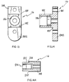
- Hub portion 192 has a threaded bore 196 for receiving a threaded end portion 198 of a rotatable coupling shaft member 200 (Fig. 14A).
- the upper end portion 202 of coupling shaft member 200 is rotatably supported by and mounted in a support plate member 203.
- a threaded nut 204 is fixedly mounted in a central bore 206 of shaft member 200 and threadably connected to a threaded lover end portion 206 of the reversely rotatable drive shaft of the lowermost gap adjustment solenoid unit 114 as hereinafter described.
- the construction and arrangement is such that rotation of solenoid drive shaft causes rotation of the coupling shaft and axial up or down displacement of the coupling member 190 and the needle actuating solenoid mounted thereon.
- Each of the adjustment solenoid means 112, 114 is provided by a generally conventional unidirectional low voltage direct current stepping solenoid as shown and described on pages SS1-6 of the catalog of Lucas Ledex Inc. of Vandalia, Ohio.
- Each stepping solenoid comprises a cylindrical housing member 210, 212 surrounding and supporting the operational apparatus which includes a coil, an armature plate, an armature hub, a spring cage, return springs, a detent plate, an output half, detent springs, a detent rotor, a retaining rig, and an end cap.
- each stepping solenoid is operable through 36 positions in 10 step increments during each revolution.
- the stepping solenoids 112, 114 are connected by a central connecting plate 214 and mounted on end plate members 128. Upper half end portion 218 is received in and rotatably supported by a bore 219 in upper end plate member 216.
- the present invention provides eccentric nozzle location adjustment means whereby the central axis 230 of the nozzle discharge passage 158 may be moved along an arc relative to the container lid member.
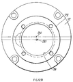
- the outer cylindrical surface 232 of intermediate housing portion 122 has a central axis 234 which is eccentrically of set relative to central axis 230.
- Upper housing portion 124 also has a central axis 236 which is offset relative to central axis 230.
- Housing portion 122 is rotatably supported in a cylindrical bore in a releasable clamp member (not shown) so as to be rotatable therein to vary the location of the nozzle.
Landscapes
- Engineering & Computer Science (AREA)
- Mechanical Engineering (AREA)
- Robotics (AREA)
- Coating Apparatus (AREA)
- Sampling And Sample Adjustment (AREA)
- Nozzles (AREA)
- Threshing Machine Elements (AREA)
- Developing Agents For Electrophotography (AREA)
- Catching Or Destruction (AREA)
- Seal Device For Vehicle (AREA)
- Application Of Or Painting With Fluid Materials (AREA)
- Transition And Organic Metals Composition Catalysts For Addition Polymerization (AREA)
- Paper (AREA)
Abstract
Description
- This invention relates generally to a system for dispensing fluids, and more particularly to a sealant delivery system and apparatus for application of a sealant compound material to container lids and closures of the type disclosed in United States patent No. 4,262,629 and No. 4,840,138.
- In general, the apparatus of U.S. patents No. 4,262,629 and No. 4,840,138 comprises a rotary can lid feed mechanism having a series of pockets which are advanced through a downstacker area to laterally shift each lowermost lid in succession of the stack of lids along an arcuate guide path into each of a series of shallow recesses formed in a rotary chuck table. The rotary chuck table has a series of lift chucks disposed in normally lowered position beneath the recesses, and a rotary drive is operative to synchronously rotate the table and lift chucks at a predetermined rate of speed. A cam member located in the path of travel of the lift chucks is operative to advance each lift chuck in succession when it is received at a first station between a normally lowered position and a raised position through a distance corresponding to two stations, after which the lid is lowered as it is advanced to a third station and discharged into a collection area. The empty recess then continues through a distance corresponding to three more stations before it picks up another can lid. An upper sealant gun assembly includes a spring-loaded chuck aligned with each recess to as to be engageable with each lid as it is raised by the lift chuck to activate an associated sealant gun in response to such engagement. The sealant is discharged from the gun as the can lid is caused to rotate about its own axis by rotation of the lift chuck through the first two stations so as to uniformly deposit the lining material into the groove of each can lid in succession. Again, following application of the sealant, the can lid is lowered by the lift chuck, then disengaged so as to permit the can lid to be discharged from the table preferably by the rotary speed of rotation of the table into a discharge or collection area. Feed interrupt mechanism is provided for interrupting advancement of the can lids from the downstacker area in passing in the event of misalignment of a lid; also, an interrupt mechanism is provided in association with the sealant gun to interrupt delivery of sealant in the event that the can lid is not properly aligned with respect to a recess on the chuck table. Preferably, both interrupt mechanisms are controlled by a common sensor in the rotary feed mechanism; however, a separate sensor is provided on the upper chuck assembly to interrupt supply of sealant. Apparatus of this type has been successfully employed with sealant material made from a non-abrasive, non-corrosive solvent base compound which does not present any significant problems in the sealant delivery system.
- The apparatus of U.S. patent No. 4,840,138 provides a sealant dispensing system for use with a conventional rotary-type sealant-applying machine wherein a plurality of circumferentially spaced sealant supply hose means connect a sealant supply means to a plurality of circumferentially spaced sealant dispensing head means which rotate about a central axis of rotation. The sealant supply means is located in coaxial relationship with the central axis of rotation and rotates thereabout and comprises an elongated vertical rotatable supply chamber means in which a supply of sealant is maintained under pressure by a supply of compressed air for delivery to the sealant dispensing head means through the supply hose means.
- A spindle means is attached to the supply chamber means for rotation therewith and extends into a non-rotatable support housing with bearing means mounted therebetween. The support housing means and the spindle means have coaxial aligned central passages which are coaxial with the central axis of rotation. Sealing means are mounted between the spindle means and the support housing means to prevent escape of air from the air passage means. Sealant is delivered to the supply chamber means through a non-rotatable central tubular passage means mounted in the housing and spindle passage means in coaxial alignment with the central axis of rotation. Air is delivered to the supply chamber means through an annular passage means circumjacent the tubular passage means. Electrical sensing means are provided to monitor the amount of sealant in the supply chamber means and to cause additional amounts of sealant to be automatically delivered to the supply chamber when a lower chamber level of sealant is detected and to terminate delivery when an upper maximum sealant level is reached. The sensing means are activated by contact with the conductive water-base sealant compound. The construction and arrangement is such that the sealant does not contact any part of the spindle means nor, the support housing means nor the bearing and sealing means associated therewith.
- The nozzle apparatus of U.S. patent No. 4,262,629 and No. 4,840,138 was actuated between open and closed positions by a mechanical linkage and the size of the dispensing opening was adjusted by a mechanical linkage. Some attempts have been made to provide electric operated pneumatic and/or hydraulic actuation systems.
- U.S. Patent No. 4,339,482, discloses dispensing material with a solenoid actuated dispensing device including a solenoid value having a main body with a valve seat body. The main body contains an axially movable valve stem needle which is spring biased closed against an outlet opening when a separately housed actuating solenoid coil, coupled to the valve stem needle is de-energized. Adjustment in the flow gap thorough the outlet opening is manually performed by rotating a solenoid assembly relative to the main body to cause the main body to move axially towards or away from the solenoid assembly.
- U.S. Patent No. 5,133,033 discloses an electrically controlled valve apparatus for dispensing viscous plastic to form a sealing ring around the underside of bottle caps. The valve apparatus provides for a flow gap adjustment by way of a manual turn screw arrangement. Rotation of a knob, attached to a threaded shaft, causes a coil supporting body to move up or down relative to a main body member. Since the upper coil member is attached to the coil supporting body, rotation of the knob and the threaded shaft causes corresponding up and down movement of the upper coil member to provide adjustment of the amount the needle valve may open.
- U.S. Patent No. 3,412,971 discloses a flow gap adjustment by way of a manual turn screw arrangement. Rotation of a knob attached to a threaded shaft, causes a coil supporting body to move up or down relative to the main body member. As the upper coil member is attached to the coil supporting body, rotation of the knob and the threaded shaft causes up and down movement of the upper coil member. The up and down movement of the upper coil member provides an adjustment in the distance the needle valve may open when the coil is actuated.
- U.S. Patent No. 4,437,488 discloses dispensing a plastic material with a solenoid actuated dispensing device including a solenoid valve with a main body. The main body includes a valve seat body containing an axially movable valve stem needle which is spring biased closed against an outlet opening. The valve stem needle is retracted from the outlet opening by a separately housed, actuating solenoid coil coupled to the valve steam needle. The solenoid assembly is rotated relative to the valve main body and coupled to the main body by a threaded connection. Rotation of the solenoid assembly causes the main body to move axially towards or away from the solenoid assembly resulting in an adjustment to the flow gap.
- It is the object of the invention to improve the adjustments to the dispence rate of the sealant while the sealant machine is operational.
- According to the present invention there is provided a sealant applying machine for applying sealant to can lid members including a sealant dispensing device with an elongated housing for supporting the components of the sealant dispensing device and having a lower housing portion, an upper housing portion and an intermediate housing portion, a nozzle on the lower housing portion having a sealant dispensing opening, a needle valve seat surface and a sealant flow passage, a needle valve axially slidable in the lower housing portion and being selectively axially movable between an open sealant applying position and a closed non-flow position relative to said needle valve seat surface, a spring mounted in said lower housing portion and being operatively associated with said needle valve to normally hold said needle valve in the closed position, and a needle valve actuator solenoid being operatively connected to said needle valve for selectively causing axial movement of said needle valve form the closed position to the open position by a predetermined axial distance to provide a predeterminedsealant flow gap in said nozzle to dispense a predetermined amount of sealant material during a predetermined dispensing time period, characterized in that said sealant dispensing device incudes a flow gap adjustment solenoid mounted in said upper housing portion and being operatively connected to said needle valve actuator solenoid mounted in said intermediate housing portion for selectively changing the amount of axial movement of said needle valve caused by said actuator solenoid so as to selectively vary the sealant flow gap and the amount of sealant material dispensed during a predetermined dispensing time, and in that the machine further includes a plurality of circumferential spaced sealant applying stations with a lid holding mechanism for holding and rotating a lid member during application of the sealant to the lid member, a rotatable carriage mechanism for supporting and carrying sealant stations around the machine, and a mounting mechanism for holding said sealant dispensing device in a fixed, non-movable relationship to said lid holding mechanism during application of the sealant to the lid members.
- Further embodiments of the invention are defined in the dependent claims.
- An illustrative and presently preferred embodiment of the invention is shown in the accompanying drawing which:
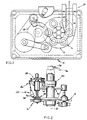
- Fig. 1 is a plan view of the prior art apparatus;
- Fig. 2 is a partial enlarged side elevational view of the apparatus of Fig. 1;
- Fig 3 is an enlarged cross-sectional view of a prior art mechanical nozzle actuation and adjustment assembly;
- Fig. 4 is an schematic side view of the prior art fluid dispensing system; and
- Fi s. 5A and 5B are enlarged cross-sectional view of the automatic electronic nozzle actuating and adjustment system of the present invention;
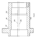
- Fig 6 is a cross-sectional side elevational view of the lower housing portion;
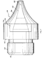
- Fig. 7 is a side elevational view of the nozzle;
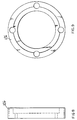
- Fig. 8 is a side elevational view of the clamp ring;
- Fig. 9 is an end view of the clamp ring;
- Fig. 10 is a side view of the needle valve member;
- Fig. 11 is a side elevational view of the needle valve actuating solenoid coupling member;
- Fig. 11A is an end view of the needle valve actuating solenoid connecting member;
- Fig. 12 is a cross-sectional side elevational view of the intermediate housing portion;
- Fig. 12A is an upper end view of the intermediate housing portion;
- Fig. 12B is a lower end view of the intermediate housing portion;
- Fig. 13 is an end view of the actuating solenoid mounting plate and adjustable solenoid coupling member;
- Fig: 14 is a cross-sectional side elevational view of the apparatus shown in Fig. 13;
- Fig. 14A is a cross-sectional view of the threaded nut coupling member;
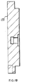
- Fig. 15 is a cross-sectional side elevational view of the upper housing portion;
- Fig. 15A is an upper end view of the upper housing portion;
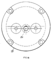
- Fig. 15B is a lower end view of the upper housing portion;
- Fig. 16 is an end view of the lower mounting plate member;
- Fig. 17 is a cross-sectional view of the mounting plate member of Fig. 16;
- Fig. 18 is an end view of the housing end plate member; and
- Fig. 19 is a cross-sectional view of the housing end plate member.
-
- In general, Figs. 1 & 2 show a conventional can lid
sealant applying machine 10 which comprises a rotatable star wheel feed means 12 for transferring can lids to a rotatable support wheel means 14 for supporting a plurality of circumferentially spaced lid support means 16 for rotation about a central axis ofrotation 18 to a discharge track means 20 for removal of can lids after sealant has been applied thereto. - Fig. 2 shows the conventional sealant applying means which comprises a plurality of circumferential spaced lid holding means 22 for holding the lids on support means 16 and associated sealant applying nozzle means 24 for applying sealant to the lids during rotation of the lid support means 16. Each sealant applying nozzle means 24 has a linkage means 26 for controlling position of and supply of sealant to sealant applying nozzle means 24. The sealant applying nozzle means 24 and associated means are mounted on rotatable bracket means and hub means 30, 32 for rotation about
central axis 18. A sealant supply chamber means 34 suitably mounted on bracket hub means 30, 32 is connected to each sealant supply means 24 through suitable supply hose means 36, 38. - Fig. 3 shows a conventional mechanically actuated and adjusted nozzle means 24 which comprises a mounting
plate member 40, asupport housing member 41 and acylindrical needle member 42 having a relatively large diameterupper end portion 42a, a relatively small diameterlower portion 42b with a conical end portion 42c and a connectingflange portion 42d. Anozzle end member 44 has aconical needle seat 44a above acylindrical dispensing passage 44b. Asealant holding chamber 45 has asealant inlet passage 45a and anoutlet passage 45b suitably connected to a hose member (not shown) in a solvent-based sealant recirculation system or plugged by a suitable plug member (not shown) in a water-based sealant system.Needle member 42 is reciprocably mounted in bearingmembers 46a, 46b for movement between a lowermost closed-seated position and a variably adjustable raised dispensing position (not shown).Needle member 41 is normally held in the closed-seated position by acompression spring 47d mounted between bearingmembers 46a, 46b and operable againstneedle flange 42d through movable bearing member 46b. Lowerneedle end portion 42b extends through a packing-sealingassembly 47 to prevent escape of sealant and vapors from the sealant chamber. The assembly comprises a cup member 47a, a sealingring member 47b and a plurality of packing rings 47c. Anadjustment nut 48 is threadably mounted on cup member 47a. - Fig. 4 shows the sealant delivery system of U.S. patent No. 4,840,138 which comprises a rotatable sealant supply chamber means 50 for holding a supply of sealant for delivery to one or more conventional dispensing head means 52, 53 through conventional supply hose means 54, 55. A spindle means 56 and conventional bearing means 58 enable rotation of supply chamber means 50 relative to a conventional non-rotatable support housing means 60. Sealant is periodically supplied to supply chamber means 50 from a large-size supply container means 62 through a conventional pump means 64, a conventional solenoid valve means 66 and supply tube means 68 mounted in and extending through support housing means 60 and spindle means 56 into supply chamber means 50. Pressurized air is continuously supplied to sealant supply chamber meant 50 from a conventional
air supply source 70 through a conventional pressure regulator means 72 and supply passage means 74 in and extending through spindle means 56 and support housing means 60 to chamber means 50. Three level sensor means 76, 78, 80 are mounted in sealant supply chamber means 50 and connected to a conventional electrical control means 82 which controls pump means 64 and solenoid valve means 66 to maintain a supply of sealant in the chamber means 50 between amaximum level 86 and aminimum level 88. This system may be used with the present invention when a water-based sealant material is being applied. - As shown in Figs. 5A & 5B, the electronically actuated and adjustable nozzle system of the present invention comprises a housing means 100, a flow control needle means 102, a sealant dispensing nozzle means 104, a sealant supply chamber means 106, a variably axially adjustable needle actuating solenoid moans 108, a lower coupling means 110 for connecting the solenoid means 108 to the flow control needle means 102, sealant flow gap adjustment solenoid means 112, 114, and an upper coupling means, 116 for connecting the needle actuator solenoid means 108 to the flow gap adjustment solenoid means 112, 114.
- Housing means 100 comprises a lowermost relatively small diameter generally cylindrical needle/nozzle
support housing portion 120, an intermediate needle actuating solenoidsupport housing portion 122, and an uppermost relatively large diameter gap adjustment solenoidsupport housing portion 124 which are stacked one upon another and suitably fixedly connected by suitable connecting means such as aring member 126, and associated threadedfastener members 127 and anend plate member 128 and associated threadedfastener members 129. - Needle means 102 comprises a lowermost relatively
small diameter portion 130 terminating in a conicallower end portion 131 and an intermediate relativelylarge diameter portion 132 connected toportion 130 byabutment flange portion 133 and terminating in an upper threaded connectingportion 134.Intermediate needle portion 132 is separably supported by an upper bushing bearing means 135 mounted in asleeve member 136. A compression spring means 137 is mounted between upper bearing means 136 andneedle flange portion 133 to bias the needle member to the closed position.Lower needle portion 131 extends through a guide bore in anabutment plate member 138 having an O-ringperipheral seal member 139 and resilient rubber polymer sealing means 142 comprising a flangedupper end portion 144 and an elongated taperedlower end portion 145. Sleeve member 136 (Fig. 10A) is threadably connected to lowerhousing portion 120 by a threadedportion 146. - Nozzle means 104 comprises a threaded
upper coupling portion 150, anabutment flange portion 152 and alowermost head portion 154 havingwrench slots 155 and an inwardlytapered end portion 156. A relatively large diameter centralsealant flow passage 157 is connected to a relatively small diameter cylindrical dispensingend passage portion 158 by aconical portion 159 which provides a needle seat.Passage 157 intersects an enlarged cylindricalsealant supply chamber 160 connected to supply and return cross passage means 162 which are suitably connected to sealant supply and return hose means (not shown) as previously described. - Needle actuator solenoid means 108 is provided by a generally conventional low-profile low voltage D.C. operate push or pull solenoid device as shown and described on pages LP 1-4 of the catalog of Lucas Ledex, Inc. of Vandalia, Ohio.
- In general, the solenoid means comprises a
cylindrical housing member 170 which holds a fixed magnetic pole hub member surrounded by a coil member (not shown), and an axially displaceable magnetic pole movable hub member fixedly mounted on ashaft member 172 havingopposite end portions 173, 174. Theshaft member 172 is slidably supported in the fixed hub member. An annularflux plate member 176 is fixedly mounted on the movable hub member to provide an auxiliary flux path. In operation, the movable hub member,armature shaft 172 andflux plate member 176 are reciprocably axially movable as a unit relative to the coil, fixed pole hub piece and housing. In the present invention, the amount of axial movement is preferably between 1,016 and 1,219 mm (.040 and .048 inch). In the present invention, lowershaft end portion 174 is provided with threads and is threadably connected to the lower coupling means 110 and thus, operably connected to the needle member. The outer cylindrical side surface ofsolenoid housing member 170 is axially slidably adjustably mounted in and supported by a cylindricalinner surface 178 of the intermediatesupport housing portion 122. The upper end of the solenoid housing member is connected to and fixedly mounted on the upper coupling means 116 by suitable fastening means. - The lower coupling means 110 comprises a
split coupling member 180 having coaxial threadedbore portions shaft end portion 174 and threadedneedle end portion 134. The construction and arrangement is such that energization ofsolenoid 108 causes axial upward movement ofsolenoid armature shaft 172 and corresponding axial upward movement ofneedle member 102 against the bias ofspring 137 to move the needle off the nozzle needle seat a predetermined distance equal to the stroke of the solenoid armature shaft. - The upper coupling means comprises a
coupling member 190 having anannular hub portion 192 and anannular flange portion 194 with acentral bore 195 to slidably receive the upper end portion 173 of thesolenoid shaft 172. Oneend 194a offlange portion 194 is elongated to provide a key portion to engage a slot inhousing portion 122 and prevent rotation ofsolenoid housing 108.Hub portion 192 has a threadedbore 196 for receiving a threadedend portion 198 of a rotatable coupling shaft member 200 (Fig. 14A). Theupper end portion 202 ofcoupling shaft member 200 is rotatably supported by and mounted in asupport plate member 203. A threadednut 204 is fixedly mounted in acentral bore 206 ofshaft member 200 and threadably connected to a threadedlover end portion 206 of the reversely rotatable drive shaft of the lowermost gapadjustment solenoid unit 114 as hereinafter described. The construction and arrangement is such that rotation of solenoid drive shaft causes rotation of the coupling shaft and axial up or down displacement of thecoupling member 190 and the needle actuating solenoid mounted thereon. - Each of the adjustment solenoid means 112, 114 is provided by a generally conventional unidirectional low voltage direct current stepping solenoid as shown and described on pages SS1-6 of the catalog of Lucas Ledex Inc. of Vandalia, Ohio.
- Each stepping solenoid comprises a
cylindrical housing member - The stepping solenoids are reversely unidirectional so that separate energization of one solenoid causes rotation in one direction and separate energization of the other solenoid causes rotation in the opposite direction. In the presently preferred embodiment, each stepping solenoid is operable through 36 positions in 10 step increments during each revolution. The stepping
solenoids plate 214 and mounted onend plate members 128. Upperhalf end portion 218 is received in and rotatably supported by abore 219 in upper end plate member 216. - The present invention provides eccentric nozzle location adjustment means whereby the
central axis 230 of thenozzle discharge passage 158 may be moved along an arc relative to the container lid member. The outercylindrical surface 232 ofintermediate housing portion 122 has acentral axis 234 which is eccentrically of set relative tocentral axis 230.Upper housing portion 124 also has acentral axis 236 which is offset relative tocentral axis 230.Housing portion 122 is rotatably supported in a cylindrical bore in a releasable clamp member (not shown) so as to be rotatable therein to vary the location of the nozzle.
Claims (5)
- A sealant applying machine for applying sealant to can lid members including a sealant dispensing device (24) with an elongated housing (100) for supporting the components of the sealant dispensing device (24) and having a lower housing portion (120), an upper housing portion (214) and an intermediate housing portion (122), a nozzle (104) on the lower housing portion (120) having a sealant dispensing opening (158), a needle valve seat surface (159) and a sealant flow passage (157), a needle valve (102) axially slidable in the lower housing portion (120) and being selectively axially movable between an open sealant applying position and a closed non-flow position relative to said needle valve seat surface (159), a spring (137) mounted in said lower housing portion (102) and being operatively associated with said needle valve (102) to normally hold said needle valve (102) in the closed position, and a needle valve actuator solenoid (108) being operatively connected to said needle valve (102) for selectively causing axial movement of said needle valve (102) from the closed position to the open position by a predetermined axial distance to provide a predetermined sealant flow gap in said nozzle (104) to dispense a predetermined amount of sealant material during a predetermined dispensing time period, characterized in that said sealant dispensing device (24) includes a flow gap adjustment solenoid (112, 114) mounted in said upper housing portion (214) and being operatively connected to said needle valve actuator solenoid (108) mounted in said intermediate housing portion (122) for selectively changing the amount of axial movement of said needle valve (102) caused by said actuator solenoid (108) so as to selectively vary the sealant flow gap and the amount of sealant material dispensed during a predetermined dispensing time, and in that the machine further includes a plurality of circumferential spaced sealant applying stations with a lid holding mechanism (22, 16, 14) for holding and rotating a lid member during application of the sealant to the lid member, a rotatable carriage mechanism (30, 32) for supporting and carrying said sealant stations around the machine, and a mounting mechanism (26) for holding said sealant dispensing device (24) in a fixed, non-movable relationship to said lid holding mechanism (22, 16, 14) during application of the sealant to the lid members.
- The machine according to claim 1, characterized in that the needle valve actuator solenoid (108) includes a low voltage direct current operated push-pull type device having a coil portion and an armature shaft portion (172) which is axially displaceable relative to said coil portion and a flange portion (194) attached to said coil portion.
- The machine according to claims 1 or 2, characterized in that the flow gap adjustment solenoid (112, 114) includes at least one low voltage direct current actuated bidirectional rotational stepping-type solenoid device (112, 114) having at least one rotatable shaft portion (200) which is reversely rotatable to cause variation of the amount of axial displacement of the needle valve actuator solenoid.
- The machine according to claim 3, characterized further by a solenoid coupling mechanism (116) between the needle valve actuator solenoid (108) and the flow gap adjustment solenoid (112, 114).
- The machine according to claim 4, characterized in that the solenoid coupling mechanism (116) includes a threaded flange member portion (192) on the flange member (194) of the needle valve actuator solenoid (108), a threaded lower end shaft portion (198) on the rotatable shaft portion (200) of the flow gap adjustment solenoid (114), and at least on threaded coupling member (204) connected to said threaded flange member portion (192) and said threaded lower end shaft portion (198).
Applications Claiming Priority (3)
| Application Number | Priority Date | Filing Date | Title |
|---|---|---|---|
| US66665691A | 1991-03-08 | 1991-03-08 | |
| US666656 | 1991-03-08 | ||
| PCT/US1992/001751 WO1992015402A1 (en) | 1991-03-08 | 1992-03-06 | Fluid dispensing system |
Publications (3)
| Publication Number | Publication Date |
|---|---|
| EP0576593A1 EP0576593A1 (en) | 1994-01-05 |
| EP0576593A4 EP0576593A4 (en) | 1995-01-18 |
| EP0576593B1 true EP0576593B1 (en) | 2000-08-16 |
Family
ID=24674909
Family Applications (1)
| Application Number | Title | Priority Date | Filing Date |
|---|---|---|---|
| EP92909533A Expired - Lifetime EP0576593B1 (en) | 1991-03-08 | 1992-03-06 | Fluid dispensing system |
Country Status (12)
| Country | Link |
|---|---|
| US (2) | US5749969A (en) |
| EP (1) | EP0576593B1 (en) |
| JP (1) | JP3217358B2 (en) |
| KR (1) | KR100226330B1 (en) |
| AT (1) | ATE195443T1 (en) |
| AU (1) | AU658884B2 (en) |
| CA (1) | CA2105591C (en) |
| DE (1) | DE69231358T2 (en) |
| ES (1) | ES2148176T3 (en) |
| GR (1) | GR3034858T3 (en) |
| UA (1) | UA32417C2 (en) |
| WO (1) | WO1992015402A1 (en) |
Cited By (1)
| Publication number | Priority date | Publication date | Assignee | Title |
|---|---|---|---|---|
| CN106475242A (en) * | 2012-05-15 | 2017-03-08 | 斯多里机械有限责任公司 | Intelligent solenoid is combined gun driver and automatic calibrating method |
Families Citing this family (27)
| Publication number | Priority date | Publication date | Assignee | Title |
|---|---|---|---|---|
| DE19680652B4 (en) * | 1995-08-04 | 2009-06-18 | Impress Group B.V. | Method and device for externally controlled application of compound in can rims |
| US6010740A (en) * | 1997-09-30 | 2000-01-04 | Preferred Machining Corporation | Fluid dispensing system |
| WO1999067812A1 (en) * | 1998-06-24 | 1999-12-29 | Medallion Technology, Llc | Chuck table for semiconductor wafer |
| US6309541B1 (en) * | 1999-10-29 | 2001-10-30 | Ontogen Corporation | Apparatus and method for multiple channel high throughput purification |
| US6391387B1 (en) | 1998-11-25 | 2002-05-21 | Preferred Machining Corporation | Pivoting fluid dispensing method |
| US6358414B1 (en) | 1999-10-29 | 2002-03-19 | Ontogen Corporation | Pressure regulation apparatus and method for multiple channel high throughput purification |
| US6578776B1 (en) | 2000-04-03 | 2003-06-17 | Hayes Products, Llc. | Single valve ready to use hose end sprayer |
| EP1333967B1 (en) * | 2000-10-24 | 2008-03-12 | Trexel, Inc. | Valve for injection molding |
| DE20020281U1 (en) * | 2000-11-30 | 2001-04-05 | Hammelmann Maschinenfabrik GmbH, 59302 Oelde | Rotary drive for a hydraulic tool |
| DE20120233U1 (en) | 2001-12-13 | 2002-05-02 | U E S Klebetechnik GmbH, 47809 Krefeld | glue valve |
| ATE387272T1 (en) * | 2002-06-05 | 2008-03-15 | Ind Penalver Sl | EDGE PROCESSING/RUBBERING APPARATUS FOR NON-ROUND METALLIC CONTAINERS LIDS |
| US8261631B2 (en) * | 2002-09-23 | 2012-09-11 | Computrol, Inc. | Rotary machine with separately controllable stations |
| US7179333B2 (en) * | 2002-09-23 | 2007-02-20 | Computrol, Inc. | Closure sealant dispenser |
| US6809294B2 (en) * | 2003-02-12 | 2004-10-26 | The Regents Of The University Of California | Apparatus for dispensing pavement sealants |
| US20040161511A1 (en) * | 2003-02-14 | 2004-08-19 | Mars Incorporated | Grinding and mixing edible fat-based slurries and emulsions using a vibratory media mill |
| US7592033B2 (en) * | 2003-07-08 | 2009-09-22 | Computrol, Inc | Variable fluid dispenser |
| US7350722B2 (en) * | 2004-02-11 | 2008-04-01 | Meadwestvaco Calmar, Inc. | Single valve ready to use sprayer |
| US7229030B2 (en) * | 2004-02-13 | 2007-06-12 | Hayes Products, Llc. | Single valve ready to use hose end sprayer |
| US8201755B2 (en) * | 2004-02-20 | 2012-06-19 | Meadwestvaco Calmar, Inc. | Single valve ready to use sprayer |
| US7325752B2 (en) * | 2004-02-20 | 2008-02-05 | Meadwestvaco Calmar, Inc. | Single valve ready to use hose end sprayer |
| US7631819B2 (en) * | 2004-02-27 | 2009-12-15 | Meadwestvaco Calmar, Inc. | Longitudinal valve ready to use hose end sprayer |
| US8826850B2 (en) | 2012-04-30 | 2014-09-09 | Stolle Machinery Company, Llc | Linear liner and associated method |
| US20170208825A1 (en) * | 2016-01-21 | 2017-07-27 | Alan Backus | Gaseous transfer device |
| CN106563615B (en) * | 2016-09-30 | 2022-09-02 | 广东立迪智能科技有限公司 | Automatic dispenser for lamp tube |
| JP7553316B2 (en) | 2020-10-14 | 2024-09-18 | トヨタ自動車東日本株式会社 | Paint injection nozzle |
| CN113457916B (en) * | 2021-06-29 | 2023-01-06 | 珠海市华亚智能科技有限公司 | Laser radar transmitter calibration assembly equipment |
| CN113600426B (en) * | 2021-08-18 | 2022-04-29 | 深圳市鸿辉烫金材料有限公司 | Even rubberizing equipment of waterproof paper |
Family Cites Families (24)
| Publication number | Priority date | Publication date | Assignee | Title |
|---|---|---|---|---|
| US2732315A (en) * | 1956-01-24 | Birkland | ||
| US2189783A (en) * | 1935-07-06 | 1940-02-13 | American Can Co | Coating machine |
| US2587538A (en) * | 1946-02-13 | 1952-02-26 | Seaman Henry | Solenoid valve |
| US3001506A (en) * | 1958-02-06 | 1961-09-26 | Fords Ltd | Machine for applying sealing compound to bottle caps |
| US3412971A (en) | 1966-03-03 | 1968-11-26 | Armstrong Cork Co | Electrically-controlled valve apparatus and control circuit suitable for use therein |
| US3521598A (en) * | 1968-06-07 | 1970-07-21 | Reynolds Metals Co | Spray coating control apparatus |
| US3612479A (en) * | 1969-07-11 | 1971-10-12 | Autoclave Eng Inc | Double seat valve |
| US3761053A (en) * | 1969-10-01 | 1973-09-25 | Sno Trik Co | High pressure valve |
| US3852095A (en) * | 1970-09-28 | 1974-12-03 | Nordson Corp | Method and apparatus for applying wax to can lid rims |
| US3780981A (en) * | 1972-01-24 | 1973-12-25 | V Horak | Automatic tank plug valve |
| US4262629A (en) * | 1977-09-22 | 1981-04-21 | Entech Corporation | Apparatus for application of sealant to can lids |
| US4342443A (en) * | 1979-10-26 | 1982-08-03 | Colt Industries Operating Corp | Multi-stage fuel metering valve assembly |
| US4295573A (en) * | 1979-12-21 | 1981-10-20 | Nordson Corporation | Method of obtaining a seal upon the interior surface of a container closure and resulting product |
| AT378242B (en) * | 1981-07-31 | 1985-07-10 | Berchtold Max Prof | FUEL INJECTION SYSTEM FOR INTERNAL COMBUSTION ENGINES, ESPECIALLY DIESEL ENGINES |
| US4437488A (en) * | 1982-05-24 | 1984-03-20 | Lockwood Technical Inc. | Solenoid valve for hot melt material |
| US4546955A (en) * | 1982-10-14 | 1985-10-15 | Honeywell Inc. | Two-stage solenoid valve |
| JPS5992333A (en) * | 1982-11-19 | 1984-05-28 | Shinriyou Seikan Kk | Coating defect detector for can lid sealing compound |
| JPS6373175A (en) * | 1986-09-17 | 1988-04-02 | Hitachi Metals Ltd | Method for measuring ferromagnetic resonance absorption rate |
| US4840138A (en) * | 1986-12-23 | 1989-06-20 | Preferred Machining Corporation | Fluid dispensing system |
| US4884720A (en) * | 1987-06-05 | 1989-12-05 | The Coca-Cola Company | Post-mix beverage dispenser valve with continuous solenoid modulation |
| US4852773A (en) * | 1987-12-28 | 1989-08-01 | Jesco Products Company, Inc. | Adjustable flow applicator for a positive displacement constant flow-rate dispenser |
| US4958769A (en) * | 1988-12-27 | 1990-09-25 | Ford Motor Company | Compressed O-ring spray gun needle valve seal |
| US5301875A (en) * | 1990-06-19 | 1994-04-12 | Cummins Engine Company, Inc. | Force balanced electronically controlled fuel injector |
| US5215587A (en) * | 1991-03-11 | 1993-06-01 | Conal Corporation | Sealant applicator for can lids |
-
1992
- 1992-03-06 WO PCT/US1992/001751 patent/WO1992015402A1/en not_active Ceased
- 1992-03-06 UA UA93004451A patent/UA32417C2/en unknown
- 1992-03-06 JP JP50957092A patent/JP3217358B2/en not_active Expired - Lifetime
- 1992-03-06 KR KR1019930702690A patent/KR100226330B1/en not_active Expired - Fee Related
- 1992-03-06 AT AT92909533T patent/ATE195443T1/en not_active IP Right Cessation
- 1992-03-06 CA CA002105591A patent/CA2105591C/en not_active Expired - Fee Related
- 1992-03-06 ES ES92909533T patent/ES2148176T3/en not_active Expired - Lifetime
- 1992-03-06 EP EP92909533A patent/EP0576593B1/en not_active Expired - Lifetime
- 1992-03-06 DE DE69231358T patent/DE69231358T2/en not_active Expired - Lifetime
- 1992-03-06 AU AU17580/92A patent/AU658884B2/en not_active Ceased
-
1996
- 1996-05-29 US US08/654,624 patent/US5749969A/en not_active Expired - Lifetime
-
1997
- 1997-07-24 US US08/899,715 patent/US5945160A/en not_active Expired - Lifetime
-
2000
- 2000-11-15 GR GR20000402547T patent/GR3034858T3/en not_active IP Right Cessation
Cited By (1)
| Publication number | Priority date | Publication date | Assignee | Title |
|---|---|---|---|---|
| CN106475242A (en) * | 2012-05-15 | 2017-03-08 | 斯多里机械有限责任公司 | Intelligent solenoid is combined gun driver and automatic calibrating method |
Also Published As
| Publication number | Publication date |
|---|---|
| JP3217358B2 (en) | 2001-10-09 |
| CA2105591A1 (en) | 1992-09-09 |
| ATE195443T1 (en) | 2000-09-15 |
| GR3034858T3 (en) | 2001-02-28 |
| US5945160A (en) | 1999-08-31 |
| EP0576593A1 (en) | 1994-01-05 |
| UA32417C2 (en) | 2000-12-15 |
| WO1992015402A1 (en) | 1992-09-17 |
| KR100226330B1 (en) | 1999-10-15 |
| ES2148176T3 (en) | 2000-10-16 |
| DE69231358T2 (en) | 2001-03-08 |
| CA2105591C (en) | 2003-04-22 |
| AU658884B2 (en) | 1995-05-04 |
| DE69231358D1 (en) | 2000-09-21 |
| EP0576593A4 (en) | 1995-01-18 |
| US5749969A (en) | 1998-05-12 |
| AU1758092A (en) | 1992-10-06 |
| JPH06505431A (en) | 1994-06-23 |
Similar Documents
| Publication | Publication Date | Title |
|---|---|---|
| US5945160A (en) | Fluid dispensing system | |
| EP1236674B1 (en) | Screw capper | |
| US4535583A (en) | Rotary type capping apparatus | |
| US4075927A (en) | Tool orienting and release mechanism for machine tool | |
| EP1735106B1 (en) | Liquid dispensing valve and method with improved stroke length calibration and fluid fittings | |
| US4532968A (en) | Rotary filling apparatus and method | |
| CN101535170A (en) | Capping machine | |
| US5960838A (en) | Valve for adjustable filling chamber | |
| AU769310B2 (en) | Fluid dispensing system for non-circular members | |
| GB2112344A (en) | Method and device for mounting a plug on a paper container | |
| US11148924B2 (en) | Filling valve and filling machine for filling receptacles | |
| US5996311A (en) | Device for tightening caps on containers | |
| EP3543205B1 (en) | Filling valve, filling machine and method for filling receptacles | |
| CA1043303A (en) | Spray dispenser | |
| GB2200059A (en) | Sealant supply system | |
| US20230339630A1 (en) | Filling apparatus | |
| JP3851498B2 (en) | Bottle cap winding device | |
| US4274456A (en) | Apparatus for dispensing fluid sealant | |
| KR100822251B1 (en) | Capping device | |
| US4246738A (en) | Air chuck for capping or uncapping machine | |
| US6113333A (en) | Apparatus and method for applying sealant to a can lid | |
| US5167266A (en) | Apparatus for filling containers with liquid | |
| US6508498B1 (en) | Holding device for holding a container and a method for fixing a container | |
| GB2174375A (en) | Closure valve-beer keys | |
| CA2907956C (en) | Holder for a container receptacle and container receptacle |
Legal Events
| Date | Code | Title | Description |
|---|---|---|---|
| PUAI | Public reference made under article 153(3) epc to a published international application that has entered the european phase |
Free format text: ORIGINAL CODE: 0009012 |
|
| 17P | Request for examination filed |
Effective date: 19931004 |
|
| AK | Designated contracting states |
Kind code of ref document: A1 Designated state(s): AT BE CH DE ES FR GB GR IT LI NL SE |
|
| A4 | Supplementary search report drawn up and despatched |
Effective date: 19941206 |
|
| AK | Designated contracting states |
Kind code of ref document: A4 Designated state(s): AT BE CH DE ES FR GB GR IT LI NL SE |
|
| 17Q | First examination report despatched |
Effective date: 19960701 |
|
| GRAG | Despatch of communication of intention to grant |
Free format text: ORIGINAL CODE: EPIDOS AGRA |
|
| GRAG | Despatch of communication of intention to grant |
Free format text: ORIGINAL CODE: EPIDOS AGRA |
|
| GRAH | Despatch of communication of intention to grant a patent |
Free format text: ORIGINAL CODE: EPIDOS IGRA |
|
| GRAH | Despatch of communication of intention to grant a patent |
Free format text: ORIGINAL CODE: EPIDOS IGRA |
|
| GRAA | (expected) grant |
Free format text: ORIGINAL CODE: 0009210 |
|
| AK | Designated contracting states |
Kind code of ref document: B1 Designated state(s): AT BE CH DE ES FR GB GR IT LI NL SE |
|
| REF | Corresponds to: |
Ref document number: 195443 Country of ref document: AT Date of ref document: 20000915 Kind code of ref document: T |
|
| ITF | It: translation for a ep patent filed | ||
| REG | Reference to a national code |
Ref country code: CH Ref legal event code: NV Representative=s name: A. BRAUN, BRAUN, HERITIER, ESCHMANN AG PATENTANWAE Ref country code: CH Ref legal event code: EP |
|
| REF | Corresponds to: |
Ref document number: 69231358 Country of ref document: DE Date of ref document: 20000921 |
|
| REG | Reference to a national code |
Ref country code: ES Ref legal event code: FG2A Ref document number: 2148176 Country of ref document: ES Kind code of ref document: T3 |
|
| ET | Fr: translation filed | ||
| PLBE | No opposition filed within time limit |
Free format text: ORIGINAL CODE: 0009261 |
|
| 26N | No opposition filed | ||
| REG | Reference to a national code |
Ref country code: GB Ref legal event code: IF02 |
|
| PGFP | Annual fee paid to national office [announced via postgrant information from national office to epo] |
Ref country code: GR Payment date: 20040116 Year of fee payment: 13 |
|
| PGFP | Annual fee paid to national office [announced via postgrant information from national office to epo] |
Ref country code: AT Payment date: 20040205 Year of fee payment: 13 |
|
| PGFP | Annual fee paid to national office [announced via postgrant information from national office to epo] |
Ref country code: SE Payment date: 20040303 Year of fee payment: 13 |
|
| PGFP | Annual fee paid to national office [announced via postgrant information from national office to epo] |
Ref country code: CH Payment date: 20040319 Year of fee payment: 13 |
|
| PGFP | Annual fee paid to national office [announced via postgrant information from national office to epo] |
Ref country code: BE Payment date: 20040416 Year of fee payment: 13 |
|
| BECH | Be: change of holder |
Owner name: *ALCOA PACKAGING MACHINERY INC. Effective date: 20050111 |
|
| REG | Reference to a national code |
Ref country code: CH Ref legal event code: PUE Owner name: ALCOA PACKAGING MACHINERY, INC. Free format text: PREFERRED MACHINING CORPORATION#3730 SOUTH KALAMATH#ENGLEWOOD COLORADO 80110 (US) -TRANSFER TO- ALCOA PACKAGING MACHINERY, INC.#6949 SOUTH POTOMAC STREET#ENGLEWOOD, CO 80112 (US) |
|
| PG25 | Lapsed in a contracting state [announced via postgrant information from national office to epo] |
Ref country code: AT Free format text: LAPSE BECAUSE OF NON-PAYMENT OF DUE FEES Effective date: 20050306 |
|
| PG25 | Lapsed in a contracting state [announced via postgrant information from national office to epo] |
Ref country code: SE Free format text: LAPSE BECAUSE OF NON-PAYMENT OF DUE FEES Effective date: 20050307 |
|
| REG | Reference to a national code |
Ref country code: GB Ref legal event code: 732E |
|
| PG25 | Lapsed in a contracting state [announced via postgrant information from national office to epo] |
Ref country code: LI Free format text: LAPSE BECAUSE OF NON-PAYMENT OF DUE FEES Effective date: 20050331 Ref country code: CH Free format text: LAPSE BECAUSE OF NON-PAYMENT OF DUE FEES Effective date: 20050331 Ref country code: BE Free format text: LAPSE BECAUSE OF NON-PAYMENT OF DUE FEES Effective date: 20050331 |
|
| NLS | Nl: assignments of ep-patents |
Owner name: ALCOA PACKAGING MACHINERY, INC. |
|
| NLT1 | Nl: modifications of names registered in virtue of documents presented to the patent office pursuant to art. 16 a, paragraph 1 |
Owner name: YOUNT CORP. |
|
| REG | Reference to a national code |
Ref country code: FR Ref legal event code: TP |
|
| BERE | Be: lapsed |
Owner name: *ALCOA PACKAGING MACHINERY INC. Effective date: 20050331 |
|
| REG | Reference to a national code |
Ref country code: ES Ref legal event code: PC2A |
|
| PG25 | Lapsed in a contracting state [announced via postgrant information from national office to epo] |
Ref country code: GR Free format text: LAPSE BECAUSE OF NON-PAYMENT OF DUE FEES Effective date: 20051004 |
|
| EUG | Se: european patent has lapsed | ||
| REG | Reference to a national code |
Ref country code: CH Ref legal event code: PL |
|
| BECH | Be: change of holder |
Owner name: *ALCOA PACKAGING MACHINERY INC. Effective date: 20050111 |
|
| BERE | Be: lapsed |
Owner name: *ALCOA PACKAGING MACHINERY INC. Effective date: 20050331 |
|
| PGFP | Annual fee paid to national office [announced via postgrant information from national office to epo] |
Ref country code: FR Payment date: 20110317 Year of fee payment: 20 Ref country code: IT Payment date: 20110315 Year of fee payment: 20 Ref country code: NL Payment date: 20110317 Year of fee payment: 20 |
|
| PGFP | Annual fee paid to national office [announced via postgrant information from national office to epo] |
Ref country code: ES Payment date: 20110414 Year of fee payment: 20 Ref country code: GB Payment date: 20110302 Year of fee payment: 20 Ref country code: DE Payment date: 20110302 Year of fee payment: 20 |
|
| REG | Reference to a national code |
Ref country code: DE Ref legal event code: R071 Ref document number: 69231358 Country of ref document: DE |
|
| REG | Reference to a national code |
Ref country code: DE Ref legal event code: R071 Ref document number: 69231358 Country of ref document: DE |
|
| REG | Reference to a national code |
Ref country code: NL Ref legal event code: V4 Effective date: 20120306 |
|
| REG | Reference to a national code |
Ref country code: GB Ref legal event code: PE20 Expiry date: 20120305 |
|
| PG25 | Lapsed in a contracting state [announced via postgrant information from national office to epo] |
Ref country code: DE Free format text: LAPSE BECAUSE OF EXPIRATION OF PROTECTION Effective date: 20120307 |
|
| REG | Reference to a national code |
Ref country code: ES Ref legal event code: FD2A Effective date: 20120604 |
|
| PG25 | Lapsed in a contracting state [announced via postgrant information from national office to epo] |
Ref country code: GB Free format text: LAPSE BECAUSE OF EXPIRATION OF PROTECTION Effective date: 20120305 |
|
| PG25 | Lapsed in a contracting state [announced via postgrant information from national office to epo] |
Ref country code: ES Free format text: LAPSE BECAUSE OF EXPIRATION OF PROTECTION Effective date: 20120307 |