EP0576518B1 - Multicylinder two-stroke engine intake manifold - Google Patents
Multicylinder two-stroke engine intake manifold Download PDFInfo
- Publication number
- EP0576518B1 EP0576518B1 EP92906922A EP92906922A EP0576518B1 EP 0576518 B1 EP0576518 B1 EP 0576518B1 EP 92906922 A EP92906922 A EP 92906922A EP 92906922 A EP92906922 A EP 92906922A EP 0576518 B1 EP0576518 B1 EP 0576518B1
- Authority
- EP
- European Patent Office
- Prior art keywords
- cavity
- cylinder
- manifold
- cylinder block
- crankcase
- Prior art date
- Legal status (The legal status is an assumption and is not a legal conclusion. Google has not performed a legal analysis and makes no representation as to the accuracy of the status listed.)
- Expired - Lifetime
Links
Images


Classifications
-
- F—MECHANICAL ENGINEERING; LIGHTING; HEATING; WEAPONS; BLASTING
- F02—COMBUSTION ENGINES; HOT-GAS OR COMBUSTION-PRODUCT ENGINE PLANTS
- F02M—SUPPLYING COMBUSTION ENGINES IN GENERAL WITH COMBUSTIBLE MIXTURES OR CONSTITUENTS THEREOF
- F02M35/00—Combustion-air cleaners, air intakes, intake silencers, or induction systems specially adapted for, or arranged on, internal-combustion engines
- F02M35/10—Air intakes; Induction systems
- F02M35/104—Intake manifolds
- F02M35/112—Intake manifolds for engines with cylinders all in one line
-
- F—MECHANICAL ENGINEERING; LIGHTING; HEATING; WEAPONS; BLASTING
- F02—COMBUSTION ENGINES; HOT-GAS OR COMBUSTION-PRODUCT ENGINE PLANTS
- F02B—INTERNAL-COMBUSTION PISTON ENGINES; COMBUSTION ENGINES IN GENERAL
- F02B25/00—Engines characterised by using fresh charge for scavenging cylinders
- F02B25/26—Multi-cylinder engines other than those provided for in, or of interest apart from, groups F02B25/02 - F02B25/24
-
- F—MECHANICAL ENGINEERING; LIGHTING; HEATING; WEAPONS; BLASTING
- F02—COMBUSTION ENGINES; HOT-GAS OR COMBUSTION-PRODUCT ENGINE PLANTS
- F02M—SUPPLYING COMBUSTION ENGINES IN GENERAL WITH COMBUSTIBLE MIXTURES OR CONSTITUENTS THEREOF
- F02M35/00—Combustion-air cleaners, air intakes, intake silencers, or induction systems specially adapted for, or arranged on, internal-combustion engines
- F02M35/10—Air intakes; Induction systems
- F02M35/10006—Air intakes; Induction systems characterised by the position of elements of the air intake system in direction of the air intake flow, i.e. between ambient air inlet and supply to the combustion chamber
- F02M35/10078—Connections of intake systems to the engine
-
- F—MECHANICAL ENGINEERING; LIGHTING; HEATING; WEAPONS; BLASTING
- F02—COMBUSTION ENGINES; HOT-GAS OR COMBUSTION-PRODUCT ENGINE PLANTS
- F02M—SUPPLYING COMBUSTION ENGINES IN GENERAL WITH COMBUSTIBLE MIXTURES OR CONSTITUENTS THEREOF
- F02M35/00—Combustion-air cleaners, air intakes, intake silencers, or induction systems specially adapted for, or arranged on, internal-combustion engines
- F02M35/10—Air intakes; Induction systems
- F02M35/10091—Air intakes; Induction systems characterised by details of intake ducts: shapes; connections; arrangements
- F02M35/10111—Substantially V-, C- or U-shaped ducts in direction of the flow path
-
- F—MECHANICAL ENGINEERING; LIGHTING; HEATING; WEAPONS; BLASTING
- F02—COMBUSTION ENGINES; HOT-GAS OR COMBUSTION-PRODUCT ENGINE PLANTS
- F02M—SUPPLYING COMBUSTION ENGINES IN GENERAL WITH COMBUSTIBLE MIXTURES OR CONSTITUENTS THEREOF
- F02M35/00—Combustion-air cleaners, air intakes, intake silencers, or induction systems specially adapted for, or arranged on, internal-combustion engines
- F02M35/10—Air intakes; Induction systems
- F02M35/10091—Air intakes; Induction systems characterised by details of intake ducts: shapes; connections; arrangements
- F02M35/10124—Ducts with special cross-sections, e.g. non-circular cross-section
-
- F—MECHANICAL ENGINEERING; LIGHTING; HEATING; WEAPONS; BLASTING
- F02—COMBUSTION ENGINES; HOT-GAS OR COMBUSTION-PRODUCT ENGINE PLANTS
- F02M—SUPPLYING COMBUSTION ENGINES IN GENERAL WITH COMBUSTIBLE MIXTURES OR CONSTITUENTS THEREOF
- F02M35/00—Combustion-air cleaners, air intakes, intake silencers, or induction systems specially adapted for, or arranged on, internal-combustion engines
- F02M35/10—Air intakes; Induction systems
- F02M35/1015—Air intakes; Induction systems characterised by the engine type
- F02M35/1019—Two-stroke engines; Reverse-flow scavenged or cross scavenged engines
-
- F—MECHANICAL ENGINEERING; LIGHTING; HEATING; WEAPONS; BLASTING
- F02—COMBUSTION ENGINES; HOT-GAS OR COMBUSTION-PRODUCT ENGINE PLANTS
- F02M—SUPPLYING COMBUSTION ENGINES IN GENERAL WITH COMBUSTIBLE MIXTURES OR CONSTITUENTS THEREOF
- F02M35/00—Combustion-air cleaners, air intakes, intake silencers, or induction systems specially adapted for, or arranged on, internal-combustion engines
- F02M35/10—Air intakes; Induction systems
- F02M35/10242—Devices or means connected to or integrated into air intakes; Air intakes combined with other engine or vehicle parts
- F02M35/10275—Means to avoid a change in direction of incoming fluid, e.g. all intake ducts diverging from plenum chamber at acute angles; Check valves; Flame arrestors for backfire prevention
-
- F—MECHANICAL ENGINEERING; LIGHTING; HEATING; WEAPONS; BLASTING
- F02—COMBUSTION ENGINES; HOT-GAS OR COMBUSTION-PRODUCT ENGINE PLANTS
- F02M—SUPPLYING COMBUSTION ENGINES IN GENERAL WITH COMBUSTIBLE MIXTURES OR CONSTITUENTS THEREOF
- F02M35/00—Combustion-air cleaners, air intakes, intake silencers, or induction systems specially adapted for, or arranged on, internal-combustion engines
- F02M35/10—Air intakes; Induction systems
- F02M35/10242—Devices or means connected to or integrated into air intakes; Air intakes combined with other engine or vehicle parts
- F02M35/10288—Air intakes combined with another engine part, e.g. cylinder head cover or being cast in one piece with the exhaust manifold, cylinder head or engine block
-
- F—MECHANICAL ENGINEERING; LIGHTING; HEATING; WEAPONS; BLASTING
- F02—COMBUSTION ENGINES; HOT-GAS OR COMBUSTION-PRODUCT ENGINE PLANTS
- F02B—INTERNAL-COMBUSTION PISTON ENGINES; COMBUSTION ENGINES IN GENERAL
- F02B75/00—Other engines
- F02B75/02—Engines characterised by their cycles, e.g. six-stroke
- F02B2075/022—Engines characterised by their cycles, e.g. six-stroke having less than six strokes per cycle
- F02B2075/025—Engines characterised by their cycles, e.g. six-stroke having less than six strokes per cycle two
Definitions
- This invention relates to multi-cylinder two stroke cycle internal combustion engines having an induction manifold through which the incoming air is distributed to the respective crankcase cavities of the engine.
- the common manifold should have a capacity at least equal to the total swept volume of the engine, and preferably 1.2 to 1.5 times the total swept volume of the engine.
- the provision of a manifold of this capacity currently substantially increases the overall physical dimensions of the engine assembly together with increases in weight and material costs.
- a cylinder block for a two-stroke cycle engine which aims to reduce the dimensions of the block by arrangement of the exhaust and transfer passages therein.
- Air intake passages formed in the block project a substantial distance laterally from the main portion of the block and the form of the air induction manifold is not described.
- a multi-cylinder two stroke cycle internal combustion engine comprising a cylinder block having at least two cylinders therein, an individual crankcase cavity for each cylinder to receive the incoming air charge for the respective cylinder, said crankcase cavities having respective valve controlled intake ports in a common wall of the cylinder block, characterised in that an air induction manifold is detachably mounted to said common wall of the cylinder block to form therewith a single air induction cavity communicating with each crankcase cavity intake port, at least part of said air induction cavity being formed within the cylinder block, at least one inlet port being provided in said manifold for the entry of air to said induction cavity, said cylinder block comprising a planar face with a first opening communicating with an internal cavity within the confines of the block, said internal cavity being closed apart from said first opening, and respective second openings in the block forming or communicating with said air intake ports to the respective crankcase cavities, said manifold comprising a planar face complementary to the cylinder block planar face and having formed there
- individual passages are formed within the induction manifold to provide the communication between air induction cavity and the respective intake ports.
- the engine 10 is of the generally conventional two stroke cycle construction having a cylinder block 11 with three inline cylinders, a cylinder head 12 and crankcase 13.
- Each piston 14 is coupled by a conventional connecting rod 15 to the crankshaft 16 with the crankcase 13 and lower portion of the cylinder block 11 forming intermediate walls 17 dividing the crankcase into respective compartments 18 for the engine to operate on the conventional crankcase compression system.
- Each crankcase compartment 18 has an individual inlet port 19 in which is fitted a conventional reed valve assembly 20 that only permits a flow of air into the crankcase compartment when the pressure in the compartment is below that within the manifold 25.
- Each individual air inlet port 19 is in direct communication with the main induction chamber 27 of the manifold 25.
- a main intake passage 23 is provided at one end of the manifold communicating with the main induction chamber 27 and having a conventional throttle valve (not shown) mounted therein.
- the cylinder block 11 has an opening 39 in the wall 31 thereof of a shape to complement the shape of the open side 32 of the manifold 25.
- the cavity 38 provided within the cylinder block is accessible through the opening 39 in the side wall 31 of the cylinder block and is closed against access to atmosphere other than through the main induction chamber 27 and main air intake passage 23.
- the common wall 31 of the cylinder block has a planar surface 35 which extends completely about the periphery of the opening 39 and about each of the crankcase compartment inlet ports 19.
- the manifold 25 has a complementary planar surface 36 which extends completely about the periphery of the open side 32 of the manifold and about each of the passages 33 in the manifold that communicate with the inlet ports 19 of the crankcase compartments.
- the manifold is sealably attached to the cylinder block by the bolts 37 preferably with a gasket therebetween.
- Internal passages 33 are formed integral with the manifold 25, and located within the chamber 27. Each passage providing communication between the main induction chamber 27 and the respective inlet ports 19 in the planar face 35 of the cylinder block.
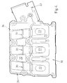
- the passages 33 are of a length determined to be "tuned" to the operation of the engine in a selected speed range to provide improved intake of air to the crankcase compartments. As seen in Figure 4, a substantial portion of the length of the passages 33 is located within the confines of the manifold. This assists in minimising the overall dimensions of the engine and manifold assembly, particularly by enabling the manifold to be located closer to the cylinder block and the inlet ports to the respective crankcase compartments while still being of the required tuned length.
- This arrangement of the passages 33 within and as part of the manifold permits simple alteration of the actual length of the passages by merely varying the height of the upper edge 30 of the respective passages 33.
- the same basic manifold casting can be used to meet a range of tuned length inlet of the inlet passages 33, with the heights of the manifold with respect to the engine block unchanged. Further the height of the manifold can be reduced to a level not higher than the cylinder head. Further, as part of the required internal volume of the induction chamber 27 is provided within the cylinder block, a reduction in overall width of the cylinder block-induction manifold assembly is achieved without reduction in the required internal volume.
Landscapes
- Engineering & Computer Science (AREA)
- Chemical & Material Sciences (AREA)
- Combustion & Propulsion (AREA)
- Mechanical Engineering (AREA)
- General Engineering & Computer Science (AREA)
- Cylinder Crankcases Of Internal Combustion Engines (AREA)
- Characterised By The Charging Evacuation (AREA)
- Control Of Throttle Valves Provided In The Intake System Or In The Exhaust System (AREA)
- Output Control And Ontrol Of Special Type Engine (AREA)
- Combustion Methods Of Internal-Combustion Engines (AREA)
Applications Claiming Priority (3)
| Application Number | Priority Date | Filing Date | Title |
|---|---|---|---|
| AU5250/91 | 1991-03-22 | ||
| AUPK525091 | 1991-03-22 | ||
| PCT/AU1992/000119 WO1992016726A1 (en) | 1991-03-22 | 1992-03-20 | Multicylinder two-stroke engine intake manifold |
Publications (3)
| Publication Number | Publication Date |
|---|---|
| EP0576518A1 EP0576518A1 (en) | 1994-01-05 |
| EP0576518A4 EP0576518A4 (cs) | 1994-02-02 |
| EP0576518B1 true EP0576518B1 (en) | 1996-01-03 |
Family
ID=3775295
Family Applications (1)
| Application Number | Title | Priority Date | Filing Date |
|---|---|---|---|
| EP92906922A Expired - Lifetime EP0576518B1 (en) | 1991-03-22 | 1992-03-20 | Multicylinder two-stroke engine intake manifold |
Country Status (13)
| Country | Link |
|---|---|
| US (1) | US5377630A (cs) |
| EP (1) | EP0576518B1 (cs) |
| JP (1) | JPH06506041A (cs) |
| AT (1) | ATE132577T1 (cs) |
| AU (1) | AU661478B2 (cs) |
| BR (1) | BR9205796A (cs) |
| CA (1) | CA2105058A1 (cs) |
| CZ (1) | CZ280652B6 (cs) |
| DE (1) | DE69207389T2 (cs) |
| ES (1) | ES2084353T3 (cs) |
| MX (1) | MX9201242A (cs) |
| TW (1) | TW221477B (cs) |
| WO (1) | WO1992016726A1 (cs) |
Families Citing this family (3)
| Publication number | Priority date | Publication date | Assignee | Title |
|---|---|---|---|---|
| US6402057B1 (en) | 2000-08-24 | 2002-06-11 | Synerject, Llc | Air assist fuel injectors and method of assembling air assist fuel injectors |
| US6484700B1 (en) | 2000-08-24 | 2002-11-26 | Synerject, Llc | Air assist fuel injectors |
| US6302337B1 (en) | 2000-08-24 | 2001-10-16 | Synerject, Llc | Sealing arrangement for air assist fuel injectors |
Family Cites Families (4)
| Publication number | Priority date | Publication date | Assignee | Title |
|---|---|---|---|---|
| US3060914A (en) * | 1957-05-06 | 1962-10-30 | Morand Max | Multi-cylinder internal combustion engines |
| AU607465B2 (en) * | 1987-02-25 | 1991-03-07 | Orbital Engine Company Proprietary Limited | Improvements relating to multi-cylindered two stroke cycle engines |
| MX167296B (es) * | 1989-02-27 | 1993-03-15 | Orbital Eng Pty | Motor de combustion interna, sobrealimentado, de cilindro multiples |
| JP2518930B2 (ja) * | 1989-07-24 | 1996-07-31 | 日産自動車株式会社 | 内燃機関の吸気装置 |
-
1992
- 1992-03-20 CZ CS931979A patent/CZ280652B6/cs not_active IP Right Cessation
- 1992-03-20 AT AT92906922T patent/ATE132577T1/de active
- 1992-03-20 US US08/107,831 patent/US5377630A/en not_active Expired - Fee Related
- 1992-03-20 WO PCT/AU1992/000119 patent/WO1992016726A1/en not_active Ceased
- 1992-03-20 ES ES92906922T patent/ES2084353T3/es not_active Expired - Lifetime
- 1992-03-20 EP EP92906922A patent/EP0576518B1/en not_active Expired - Lifetime
- 1992-03-20 BR BR9205796A patent/BR9205796A/pt not_active Application Discontinuation
- 1992-03-20 CA CA002105058A patent/CA2105058A1/en not_active Abandoned
- 1992-03-20 AU AU14220/92A patent/AU661478B2/en not_active Ceased
- 1992-03-20 MX MX9201242A patent/MX9201242A/es unknown
- 1992-03-20 DE DE69207389T patent/DE69207389T2/de not_active Expired - Fee Related
- 1992-03-20 JP JP4507081A patent/JPH06506041A/ja active Pending
- 1992-03-21 TW TW081102145A patent/TW221477B/zh active
Also Published As
| Publication number | Publication date |
|---|---|
| ES2084353T3 (es) | 1996-05-01 |
| MX9201242A (es) | 1993-01-01 |
| BR9205796A (pt) | 1994-06-28 |
| AU1422092A (en) | 1992-10-21 |
| TW221477B (cs) | 1994-03-01 |
| EP0576518A1 (en) | 1994-01-05 |
| ATE132577T1 (de) | 1996-01-15 |
| DE69207389T2 (de) | 1996-08-01 |
| WO1992016726A1 (en) | 1992-10-01 |
| DE69207389D1 (de) | 1996-02-15 |
| EP0576518A4 (cs) | 1994-02-02 |
| JPH06506041A (ja) | 1994-07-07 |
| AU661478B2 (en) | 1995-07-27 |
| CA2105058A1 (en) | 1992-09-23 |
| US5377630A (en) | 1995-01-03 |
| CZ197993A3 (en) | 1994-05-18 |
| CZ280652B6 (cs) | 1996-03-13 |
Similar Documents
| Publication | Publication Date | Title |
|---|---|---|
| CA1144078A (en) | Induction system for a v-type two-cycle engine | |
| US5005536A (en) | Engine induction system | |
| US4369627A (en) | Internal combustion engine | |
| US4951465A (en) | Exhaust system for multi-cylinder engine | |
| JPS6315542Y2 (cs) | ||
| JPS6325162B2 (cs) | ||
| KR920701624A (ko) | 다중 실린더 내연 기관 | |
| JPS6131161Y2 (cs) | ||
| US4318380A (en) | Intake system for multi-cylinder internal combustion engine | |
| US4553507A (en) | Engine with additional shared flow control runner for two cylinders | |
| ATE304654T1 (de) | Zweitaktmotor mit variabler zwangsbelüftung | |
| US5377630A (en) | Multicylinder two-stroke engine intake manifold | |
| US4567860A (en) | Intake system for multiple cylinder engines | |
| US4381738A (en) | Engine with additional shared flow control runner for two cylinders | |
| US6189503B1 (en) | Porting arrangement for direct injected engine | |
| JPS6473121A (en) | Intake device for v-row internal combustion engine | |
| US5361731A (en) | Scavenging port delivery for two stroke engine | |
| EP0244451B1 (en) | Internal combustion engine | |
| JPS6321686Y2 (cs) | ||
| GB2033962A (en) | Inlet and Exhaust Passage Arrangements for a Turbocharged I.C. Engine | |
| JP2900270B2 (ja) | 車両用エンジン | |
| US2679834A (en) | Internal-combustion engine | |
| JP3142354B2 (ja) | 2サイクルエンジン | |
| JPS597541Y2 (ja) | クランク室圧縮型多気筒2サイクルエンジン用リ−ドバルブ | |
| GB1171767A (en) | Improvements in or relating to Step-Piston-Two-Stroke Engines. |
Legal Events
| Date | Code | Title | Description |
|---|---|---|---|
| PUAI | Public reference made under article 153(3) epc to a published international application that has entered the european phase |
Free format text: ORIGINAL CODE: 0009012 |
|
| 17P | Request for examination filed |
Effective date: 19930901 |
|
| AK | Designated contracting states |
Kind code of ref document: A1 Designated state(s): AT BE CH DE DK ES FR GB GR IT LI LU MC NL SE |
|
| A4 | Supplementary search report drawn up and despatched |
Effective date: 19931213 |
|
| AK | Designated contracting states |
Kind code of ref document: A4 Designated state(s): AT BE CH DE DK ES FR GB GR IT LI LU MC NL SE |
|
| 17Q | First examination report despatched |
Effective date: 19940812 |
|
| GRAA | (expected) grant |
Free format text: ORIGINAL CODE: 0009210 |
|
| AK | Designated contracting states |
Kind code of ref document: B1 Designated state(s): AT BE CH DE DK ES FR GB GR IT LI LU MC NL SE |
|
| PG25 | Lapsed in a contracting state [announced via postgrant information from national office to epo] |
Ref country code: NL Free format text: LAPSE BECAUSE OF FAILURE TO SUBMIT A TRANSLATION OF THE DESCRIPTION OR TO PAY THE FEE WITHIN THE PRESCRIBED TIME-LIMIT Effective date: 19960103 Ref country code: LI Free format text: LAPSE BECAUSE OF FAILURE TO SUBMIT A TRANSLATION OF THE DESCRIPTION OR TO PAY THE FEE WITHIN THE PRESCRIBED TIME-LIMIT Effective date: 19960103 Ref country code: GR Free format text: LAPSE BECAUSE OF FAILURE TO SUBMIT A TRANSLATION OF THE DESCRIPTION OR TO PAY THE FEE WITHIN THE PRESCRIBED TIME-LIMIT Effective date: 19960103 Ref country code: DK Effective date: 19960103 Ref country code: CH Free format text: LAPSE BECAUSE OF FAILURE TO SUBMIT A TRANSLATION OF THE DESCRIPTION OR TO PAY THE FEE WITHIN THE PRESCRIBED TIME-LIMIT Effective date: 19960103 Ref country code: AT Effective date: 19960103 |
|
| REF | Corresponds to: |
Ref document number: 132577 Country of ref document: AT Date of ref document: 19960115 Kind code of ref document: T |
|
| REF | Corresponds to: |
Ref document number: 69207389 Country of ref document: DE Date of ref document: 19960215 |
|
| ITF | It: translation for a ep patent filed | ||
| PG25 | Lapsed in a contracting state [announced via postgrant information from national office to epo] |
Ref country code: MC Effective date: 19960320 |
|
| ET | Fr: translation filed | ||
| PG25 | Lapsed in a contracting state [announced via postgrant information from national office to epo] |
Ref country code: LU Free format text: LAPSE BECAUSE OF NON-PAYMENT OF DUE FEES Effective date: 19960331 |
|
| REG | Reference to a national code |
Ref country code: ES Ref legal event code: FG2A Ref document number: 2084353 Country of ref document: ES Kind code of ref document: T3 |
|
| NLV1 | Nl: lapsed or annulled due to failure to fulfill the requirements of art. 29p and 29m of the patents act | ||
| REG | Reference to a national code |
Ref country code: CH Ref legal event code: PL |
|
| PLBE | No opposition filed within time limit |
Free format text: ORIGINAL CODE: 0009261 |
|
| 26N | No opposition filed | ||
| PGFP | Annual fee paid to national office [announced via postgrant information from national office to epo] |
Ref country code: SE Payment date: 19990305 Year of fee payment: 8 |
|
| PGFP | Annual fee paid to national office [announced via postgrant information from national office to epo] |
Ref country code: FR Payment date: 19990309 Year of fee payment: 8 |
|
| PGFP | Annual fee paid to national office [announced via postgrant information from national office to epo] |
Ref country code: ES Payment date: 19990323 Year of fee payment: 8 |
|
| PGFP | Annual fee paid to national office [announced via postgrant information from national office to epo] |
Ref country code: GB Payment date: 19990325 Year of fee payment: 8 |
|
| PGFP | Annual fee paid to national office [announced via postgrant information from national office to epo] |
Ref country code: DE Payment date: 19990326 Year of fee payment: 8 |
|
| PGFP | Annual fee paid to national office [announced via postgrant information from national office to epo] |
Ref country code: BE Payment date: 19990517 Year of fee payment: 8 |
|
| PG25 | Lapsed in a contracting state [announced via postgrant information from national office to epo] |
Ref country code: GB Free format text: LAPSE BECAUSE OF NON-PAYMENT OF DUE FEES Effective date: 20000320 |
|
| PG25 | Lapsed in a contracting state [announced via postgrant information from national office to epo] |
Ref country code: SE Free format text: LAPSE BECAUSE OF NON-PAYMENT OF DUE FEES Effective date: 20000321 Ref country code: ES Free format text: LAPSE BECAUSE OF NON-PAYMENT OF DUE FEES Effective date: 20000321 |
|
| PG25 | Lapsed in a contracting state [announced via postgrant information from national office to epo] |
Ref country code: BE Free format text: LAPSE BECAUSE OF NON-PAYMENT OF DUE FEES Effective date: 20000331 |
|
| BERE | Be: lapsed |
Owner name: ORBITAL ENGINE CY (AUSTRALIA) PTY. LTD Effective date: 20000331 |
|
| EUG | Se: european patent has lapsed |
Ref document number: 92906922.7 |
|
| GBPC | Gb: european patent ceased through non-payment of renewal fee |
Effective date: 20000320 |
|
| PG25 | Lapsed in a contracting state [announced via postgrant information from national office to epo] |
Ref country code: FR Free format text: LAPSE BECAUSE OF NON-PAYMENT OF DUE FEES Effective date: 20001130 |
|
| REG | Reference to a national code |
Ref country code: FR Ref legal event code: ST |
|
| PG25 | Lapsed in a contracting state [announced via postgrant information from national office to epo] |
Ref country code: DE Free format text: LAPSE BECAUSE OF NON-PAYMENT OF DUE FEES Effective date: 20010103 |
|
| REG | Reference to a national code |
Ref country code: ES Ref legal event code: FD2A Effective date: 20010910 |
|
| PG25 | Lapsed in a contracting state [announced via postgrant information from national office to epo] |
Ref country code: IT Free format text: LAPSE BECAUSE OF NON-PAYMENT OF DUE FEES;WARNING: LAPSES OF ITALIAN PATENTS WITH EFFECTIVE DATE BEFORE 2007 MAY HAVE OCCURRED AT ANY TIME BEFORE 2007. THE CORRECT EFFECTIVE DATE MAY BE DIFFERENT FROM THE ONE RECORDED. Effective date: 20050320 |