EP0575670B1 - Dead-zone free optically pumped Mz magnetometer - Google Patents
Dead-zone free optically pumped Mz magnetometer Download PDFInfo
- Publication number
- EP0575670B1 EP0575670B1 EP92303797A EP92303797A EP0575670B1 EP 0575670 B1 EP0575670 B1 EP 0575670B1 EP 92303797 A EP92303797 A EP 92303797A EP 92303797 A EP92303797 A EP 92303797A EP 0575670 B1 EP0575670 B1 EP 0575670B1
- Authority
- EP
- European Patent Office
- Prior art keywords
- magnetometer
- gas cell
- lamp
- lens
- lamps
- Prior art date
- Legal status (The legal status is an assumption and is not a legal conclusion. Google has not performed a legal analysis and makes no representation as to the accuracy of the status listed.)
- Expired - Lifetime
Links
- 239000007789 gas Substances 0.000 claims description 64
- 230000005855 radiation Effects 0.000 claims description 24
- 229910052783 alkali metal Inorganic materials 0.000 claims description 11
- 150000001340 alkali metals Chemical class 0.000 claims description 11
- TVFDJXOCXUVLDH-UHFFFAOYSA-N caesium atom Chemical compound [Cs] TVFDJXOCXUVLDH-UHFFFAOYSA-N 0.000 claims description 11
- 229910052792 caesium Inorganic materials 0.000 claims description 10
- 229910052734 helium Inorganic materials 0.000 claims description 10
- 239000001307 helium Substances 0.000 claims description 10
- SWQJXJOGLNCZEY-UHFFFAOYSA-N helium atom Chemical compound [He] SWQJXJOGLNCZEY-UHFFFAOYSA-N 0.000 claims description 10
- 230000003213 activating effect Effects 0.000 claims 1
- 238000010521 absorption reaction Methods 0.000 description 9
- 230000003287 optical effect Effects 0.000 description 6
- 238000010586 diagram Methods 0.000 description 5
- 238000004804 winding Methods 0.000 description 5
- 230000000694 effects Effects 0.000 description 2
- 239000011521 glass Substances 0.000 description 2
- 230000010287 polarization Effects 0.000 description 2
- 230000001902 propagating effect Effects 0.000 description 2
- 229910052701 rubidium Inorganic materials 0.000 description 2
- IGLNJRXAVVLDKE-UHFFFAOYSA-N rubidium atom Chemical compound [Rb] IGLNJRXAVVLDKE-UHFFFAOYSA-N 0.000 description 2
- 125000006850 spacer group Chemical group 0.000 description 2
- RZVAJINKPMORJF-UHFFFAOYSA-N Acetaminophen Chemical compound CC(=O)NC1=CC=C(O)C=C1 RZVAJINKPMORJF-UHFFFAOYSA-N 0.000 description 1
- RYGMFSIKBFXOCR-UHFFFAOYSA-N Copper Chemical compound [Cu] RYGMFSIKBFXOCR-UHFFFAOYSA-N 0.000 description 1
- XUIMIQQOPSSXEZ-UHFFFAOYSA-N Silicon Chemical compound [Si] XUIMIQQOPSSXEZ-UHFFFAOYSA-N 0.000 description 1
- 239000003513 alkali Substances 0.000 description 1
- 230000005540 biological transmission Effects 0.000 description 1
- 230000008859 change Effects 0.000 description 1
- 229910052729 chemical element Inorganic materials 0.000 description 1
- 230000005670 electromagnetic radiation Effects 0.000 description 1
- -1 for example Substances 0.000 description 1
- 239000000696 magnetic material Substances 0.000 description 1
- 239000000463 material Substances 0.000 description 1
- 230000007246 mechanism Effects 0.000 description 1
- 238000000034 method Methods 0.000 description 1
- 238000012986 modification Methods 0.000 description 1
- 230000004048 modification Effects 0.000 description 1
- 230000008569 process Effects 0.000 description 1
- 238000005086 pumping Methods 0.000 description 1
- 239000005297 pyrex Substances 0.000 description 1
- 229910052710 silicon Inorganic materials 0.000 description 1
- 239000010703 silicon Substances 0.000 description 1
- 230000003595 spectral effect Effects 0.000 description 1
- 239000012780 transparent material Substances 0.000 description 1
Images


Classifications
-
- G—PHYSICS
- G01—MEASURING; TESTING
- G01R—MEASURING ELECTRIC VARIABLES; MEASURING MAGNETIC VARIABLES
- G01R33/00—Arrangements or instruments for measuring magnetic variables
- G01R33/20—Arrangements or instruments for measuring magnetic variables involving magnetic resonance
- G01R33/24—Arrangements or instruments for measuring magnetic variables involving magnetic resonance for measuring direction or magnitude of magnetic fields or magnetic flux
- G01R33/26—Arrangements or instruments for measuring magnetic variables involving magnetic resonance for measuring direction or magnitude of magnetic fields or magnetic flux using optical pumping
Definitions
- the invention relates to a dead-zone free magnetometer. More specifically, the invention relates to such a magnetometer including a gas cell, a multi-directional A.C. magnetic field H 1 formed in said cell, and at least one or more conical beams of circularly polarized resonance radiation propagating through said gas cell through said A.C. magnetic field H 1 .
- the rays of the radiation are multidirectional, i.e., non-parallel.
- Magnetometers using a gas cell (also referred to as a vapor cell or an absorption cell), using gas cells, are known in the art as illustrated in, for example, RUBIDIUM VAPOUR MAGNETOMETER, L. W. Parsons and Z. M. Wiatr, Journal of Scientific Instruments , Vol. 39, pp. 292-300, June 1962; PRINCIPLES OF OPERATION OF THE RUBIDIUM VAPOR MAGNETOMETER, A. L. Bloom, Applied Optics , Vol. 1, page 61, January 1962, U. S. Patent 4,600,886, Jensen, July 15, 1986; U. S. Patent 3,206,671, Colegrove, Jr. et al, September 14, 1965; and U. S.
- the gas cells are filled with a vapor of an alkali metal.
- D 1 or D 2 light from an alkali metal lamp is directed at the gas cell, and an alternating magnetic field H 1 is formed in the gas cell.
- the light is directed at the gas cell through a circular polarizer, and the light rays travelling through the cell travel along a single direction, i.e., all of the rays are essentially parallel to each other.
- the A.C. magnetic field H 1 formed in the gas cell is a unidirectional field with parallel lines of force.
- the Colegrove, Jr. et al and Robinson patents teach magnetometers wherein the absorption cells are filled with a helium gas and the lamps are helium lamps.
- Another solution to the dead-zone problem is to use a multiple magnetometer as suggested by Varian Associates (GB-A-964 027, published July 15, 1964) and by Mitsubishi Electric Corp. (JP-A-63-138282, published June 10, 1988).
- the above multiple magnetometer comprises three "submagnetometers" disposed at different angles.
- Such multiple magnetometer is complicated, bulky, and the electronics complex.
- Each of these magnetometers contains six gas cells and six H 1 coils.
- H 1 windings disposed at different angles are present in the magnetometer of EP-A-0462000.
- the need of the optical and electrical multiplexers in this magnetometer results from the fact that the beam of resonance radiation possesses parallel rays and every H 1 winding generates H 1 field with parallel lines of force in the gas cell of the magnetometer.
- the circularly polarized resonance radiation rays comprise circularly polarized resonance light rays.
- multi-directional when applied to light rays or magnetic fields, does not include parallel light rays or magnetic fields with parallel lines of force.
- a magnetometer in accordance with the invention comprises a gas cell 3 having a hollow enclosure which comprises a bottom surface 5 and hemispherical dome 7.
- the enclosure is made of a transparent material, for example, pyrex glass, and is, as is well known in the art, filled with either an alkali metal vapor or helium gas.
- the enclosure illustrated in the drawings of the present application has a hemi-spherical dome
- the enclosure can have other shapes, for example, it could be in the shape of an inverted cone, or it can have a semi-oval shaped cross-section.
- the bottom surface is either circular or some other shape depending on the shape of the dome.
- a mirror 9 is disposed at the bottom surface 5 of the dome 7. As can be seen in Figure 2, the mirror 9 is also circular and is concentric with the bottom member.
- a radiation emitting device for example, a lamp 11 is positioned to direct its rays towards the mirror 9 as best seen in Figure 1.
- the lamp 11 will comprise either an alkali metal vapour or helium as also well known in the art.
- the lamp 11 is a cesium lamp, and the gas cell comprises a cesium vapour.
- both the lamp and gas cell can comprise other chemical elements.
- the lamp 11 emits a light beam which is collimated by lens 13.
- Parallel rays of light pass through interference filter 15, with a peak transmission at 8944 ⁇ (cesium D 1 spectral line) and the monochromatic light then passes through a circular polarizer 17, and subsequently passes through lens 19 whereupon it enters the semi-spherical gas cell 3.
- the lens 19 focuses the light onto the plane mirror 9, and light is then reflected from the mirror 9 and the reflected light is collected onto a photosensor 25 by a lens 27.
- the photosensor comprises a photodetector, and specifically, a silicon photodetector.
- other types of photosensors may be used.
- the reflection changes the state of the polarized light from circular polarization into elliptical polarization as is well known in the art.
- the central incident and reflected rays of light make an angle of 90° to each other. It is worth noting that, upon reflection of a right hand circularly polarized light in the sensor's mirror, the light is converted to left hand polarized light and vice-versa.
- a coil 29 referred to as an H 1 coil is mounted on top of the gas cell 3 as shown in Figures 1 and 2. As seen in Figure 2, the coil is in the shape of a circle which is concentric with the circle of the bottom surface. As will be seen below, other shapes of coil may also be used.
- lamps 11 and 11a there are two lamps, 11 and 11a, as well as a separate lens arrangement with each of the lamps and a separate photosensor 25 and 25a for detecting the reflected rays of lamp 11 and 11a, respectively.
- the lamps 11 and 11a are illustrated, and preferably are, spaced 90 degrees apart.
- a lamp driver circuit 31 comprising an R.F. oscillator which provides a 100 MHz current to drive the electrodeless lamps (see, for example, U.S. Patent 3,109,960; Canadian Patent 768,824 and W. E. Bell et al, The Review of Scientific Instruments, June 1961, Vol. 32, page 688).
- the H 1 coil 29 is driven by a voltage controlled square wave or triangular wave generator 33.
- the current in the coil is frequency modulated around frequency f L which is the Larmor frequency of precessing cesium atoms.
- the driving signals for the coil are illustrated in Figures 3A and 3B.
- the sweep frequency may be approximately 900 Hz.
- At least one output of the voltage controlled square wave generator 33 and the output of the detector arrangements 25 or 25a are fed to a processor or display 35.
- H o f L /C
- H o the strength of the earth's magnetic field
- f L the Larmor frequency
- C the gyromagnetic ratio having a value 3.5 Hz/nT in the case of cesium.
- H o the strength of the earth's magnetic field
- f L the Larmor frequency
- C the gyromagnetic ratio having a value 3.5 Hz/nT in the case of cesium.
- Figures 1 and 2 show how the light rays emitted by the lamps 11 and 11a travel through the gas cell 3.
- the lamps 11 and lla are spaced 90 degrees from each other, the direction of travel of at least one of the rays is different from the direction of travel of at least another one of the rays.
- the direction of travel of any one of the rays is different from the direction of travel of any other one of the rays.
- the rays are multidirectional.
- the dotted lines 37 represent the field lines of the H 1 magnetic field formed in gas cell 3 when the H 1 coil 29 is activated. It can be seen that the direction of each field line is different from the direction of any other field line.
- the H 1 field is multidirectional. We have observed that the absorption S of the circularly polarized D 1 light travelling through a gas cell, when the materials of the gas cell and the lamp are as above described, is roughly approximate to: S ⁇ S 0 cos 4 (H 0 ,D 1 ) sin(H 0 ,H 1 ) 3/2 where S 0 is maximum absorption.
- the expression (H 0 ,D 1 ) means the angle between the earth's magnetic field H 0 and a ray of D 1 radiation, and the expression (H 0 ,H 1 ) means the angle between the H 0 and the formed H 1 field.
- the diameter of the bottom surface is of the order of 5 cm and the radius of the spherical dome is of the order of 2.5 cm.
- the lenses and the interference filters and the circular polarizers have diameters of 25.4 mm and the focal length of each lens is 32 mm.
- the bandwidth (FWHM) of the interference filter is approximately 100 ⁇ and the diameter of the active area of the photocells is of the order of 8 mm.
- the H 1 coil contains 120 turns of copper wire and the coil's diameter is 13 mm.
- the coil winding is in the form of a beehive and comprises a plurality of parallel space turns all disposed on the outer surface of the dome.
- the embodiment illustrated in Figure 6B comprises a toroidal coil.
- a narrow glass tubing 39 is needed to accommodate the wire passing through the cell.
- the lamp 11 is mounted in a lamp assembly 41.
- a collimating aspheric lens 43 is disposed in spaced relationship to the lamp, and an interference filter and a circular polarizer assembly 45 underlies the lens 43.
- a second aspheric lens 47 underlies the assembly 45, and the H 1 coil 29 is mounted in a coil assembly 49.
- the entire arrangement is housed in an outer tubular housing 51 which also includes a circular floor member 53 and a circular ceiling member 55.
- the gas cell 3 is mounted on the floor member and is coaxial therewith, and the photodetector 25 is mounted in a photodetector assembly 56 which is also coaxial with the tubular member 51.
- the center of the photodetector 25 would coincide with the axis of the tubular member.
- Optical spacers 57 space the various elements from each other.
- rays emitted by the lamp 11 are bent by the first lens 43 to form a somewhat tubular arrangement between the lenses 43 and 47.
- the rays are then further bent by the lens 47 so that the rays which travel through the gas cell form a somewhat inverted conical arrangement.
- the rays of the cone are all directed at the photodetector 25, and it can be seen that, once again, the direction of travel of the rays through the gas cells is such that the direction of travel of any one of the rays is different from the direction of travel of at least another one of the rays and, in fact, the direction of travel of any one of the rays is different from the direction of travel of any other one of the rays.
- the angle A between extreme rays of the D 1 light in the gas cell must be large - preferably 100° or more.
- FIG. 7B is identical to the embodiment illustrated in Figure 7A except that aspheric lens 43 is replaced by three positive lenses 58, 59 and 61, and aspheric lens 47 is replaced by positive lenses 63, 65 and 67.
- Figure 8 A still further embodiment is illustrated in Figure 8.
- the Figure 8 embodiment is also housed in a tubular housing 51 having a circular floor member 53 and a circular ceiling member 55.
- the lamp 11 is mounted in lamp assembly 41
- the photodetector 25 is mounted in photodetector assembly 56.
- the Figure 8 embodiment includes a parabolic reflector 69, mounted cn the floor member 53, and a second parabolic reflector, 71, mounted on the ceiling member 55.
- the parabolic reflectors are preferably parabolic mirrors.
- the lamp 11 and the photodetector 25 are mounted at the mirrors focal points.
- parabolic reflector 69 Light emitted from the lamp 11 is reflected by parabolic reflector 69 to form parallel rays between parabolic reflector 69 and parabolic reflector 71.
- Parabolic reflector 71 once again reflects light and directs it toward the photodetector so that, the light rays travelling through the gas cell 3 form a somewhat inverted conical arrangement. Some part of the light is blocked before reaching the photodetector by the opaque holder of the gas cell. This diminishes the obtained signal.
- the beam of light is conical and its rays are multidirectional.
- FIG. 9 A still further embodiment is illustrated in Figure 9.
- the arrangement of Figure 9 is housed in a tubular housing 51 having a floor member 53 and a ceiling member 55.
- the lamp 11 is once again mounted in the lamp assembly 41.
- the emitted light beam is collimated by lens 73 which can be, for example, a plano-convex lens.
- lens 73 can be, for example, a plano-convex lens.
- parallel rays of light pass through interference filter and circular polarizer assembly 45.
- the circularly polarized resonance radiation is diverged by a negative lens 75.
- the lens can be a plano-concave lens.
- the light rays impinge on a spherical photocell array 73', which overlies the gas cell 3.
- the spherical array 73' is co-axial with the gas cell.
- the apex angle of the cone of light propagating the gas cell is about 100°.
- the array of photocells can be replaced by three photocells, 25A, 25B, 25C, 45° of the symmetry axis of the sensor as shown in Figures 10A and 10B.
- the light should be focused on the photocells by converging lenses 81.
- the light rays travelling through the gas cell each travel in a direction different from at least one other light ray, and in fact, each light ray travels in a direction different from the direction of travel of any other light ray.
- Optical spacers 57 are once again provided to space the various elements from each other.
- the light rays of the light beam emitted by the lamp 11 will travel through the gas cell 3 such that the direction of travel of any light ray is different from the direction of travel of at least one other light ray and, in fact, the direction of travel of each light ray is different from the direction of travel of any other light ray travelling through the gas cell.
- the magnetic field H 1 formed in the gas cell comprises a plurality of field lines, and the direction of each field line is different from the direction of any other field line.
- the outputs of the several sensors, or the several outputs of each sensor, can be added, averaged or otherwise processed as known in the art.
- Applicant has also devised an electronic circuit for tracking the Larmor frequency. This circuit is illustrated in Figures 16, 17 and 18 herein.
- the minimum dip of the curve is referred to as the absorption point, and the V-shaped portion of the curve is referred to as the absorption curve.
- the frequency where the minimum dip occurs is referred to as the Larmor frequency f L . It is also noted that if the strength of the ambient magnetic field H 0 changes, the Larmor frequency f L will also change as shown in Figure 12.
- the average frequency f is defined as the mean frequency during one full sweep (or cycle).
- the average frequency f of the current driving the H 1 coil is equal to the Larmor frequency f L , then the output signal of the photocell is symmetrical.
- the photocell current is not symmetrical.
- the photocell current is broken down into alternating A and B zones.
- a circuit for the electronic tracking of the Larmor frequency indicated generally at 100, includes a photocell amplifier 101 and sample and hold devices 103 and 105. The outputs of the sample and hold devices are fed to a ratio comparator 107 whose output is in turn fed to an error amplifier 109.
- the sample and hold devices 103 and 105 are under the control of a control logic arrangement 111.
- the control logic which also controls the modulation frequency, will switch the sample and hold devices so that, for example, 103 will pass areas referred to as "A" in Figures 14 and 15, and 105 will pass areas referred to as "B" in Figures 14 and 15.
- the control logic 111 suppiies an output square wave signal (900 Hz) which is summed up with the output signal of the error amplifier 109 at summing point 113. The summed up signals then control the VCO 115.
- the amplifier 101 may comprise three operational amplifiers U1, U2 and U3.
- the amplifier shown in Figure 17 is configured as a transimpedance amplifier.
- the amplifier U1 is configured as a current to voltage converter.
- Operational amplifier U2 is simply a voltage amplifier.
- the operational amplifier U3 is configured as a voltage offset compensator. It adjusts the DC output of the transimpedance amplifier to zero volts.
- the ratio comparator comprises an amplifier U6 and may comprise a multiplier chip designated AD534.
- the multiplier chip 115 is configured as a ratio amplifier
- the amplitudes of A and B will be alternately fed to 103 and 105 respectively.
- a ratio of the differences between A and B is produced at the output of 107. It is important that a ratio be produced so that we are dealing with a figure that is independent of the magnitudes of A and/or B.
- the ratio is then fed to the error amplifier which in turn is fed to the summing point 113.
- the second input to the summing point 113 is fed with a modulation signal from the control logic 111, and this modulation signal is modified in the summing point 113 in accordance with the output of 109.
- This modulating voltage is then fed to the voltage controlled oscillator 115 which then provides a frequency modulated signal to drive the H 1 coil 29.
Landscapes
- Physics & Mathematics (AREA)
- Condensed Matter Physics & Semiconductors (AREA)
- General Physics & Mathematics (AREA)
- Investigating Or Analysing Materials By Optical Means (AREA)
Description
- The invention relates to a dead-zone free magnetometer. More specifically, the invention relates to such a magnetometer including a gas cell, a multi-directional A.C. magnetic field H 1 formed in said cell, and at least one or more conical beams of circularly polarized resonance radiation propagating through said gas cell through said A.C. magnetic field H 1. The rays of the radiation are multidirectional, i.e., non-parallel.
- Magnetometers, using a gas cell (also referred to as a vapor cell or an absorption cell), using gas cells, are known in the art as illustrated in, for example, RUBIDIUM VAPOUR MAGNETOMETER, L. W. Parsons and Z. M. Wiatr, Journal of Scientific Instruments, Vol. 39, pp. 292-300, June 1962; PRINCIPLES OF OPERATION OF THE RUBIDIUM VAPOR MAGNETOMETER, A. L. Bloom, Applied Optics, Vol. 1,
page 61, January 1962, U. S. Patent 4,600,886, Jensen, July 15, 1986; U. S. Patent 3,206,671, Colegrove, Jr. et al, September 14, 1965; and U. S. Patent 3,350,632, Robinson, October 31, 1967. In the Parsons et al and Bloom references, the gas cells are filled with a vapor of an alkali metal. As in known magnetometers, D1 or D2 light from an alkali metal lamp is directed at the gas cell, and an alternating magnetic field H 1 is formed in the gas cell. The light is directed at the gas cell through a circular polarizer, and the light rays travelling through the cell travel along a single direction, i.e., all of the rays are essentially parallel to each other. In a like manner, the A.C. magnetic field H 1 formed in the gas cell is a unidirectional field with parallel lines of force. - The Colegrove, Jr. et al and Robinson patents teach magnetometers wherein the absorption cells are filled with a helium gas and the lamps are helium lamps.
- Such known arrangements experience dead-zones, i.e., at some orientation of the sensor with respect to the ambient magnetic field, the sensor does not generate a signal.
- One solution to this problem has been to provide a mechanism for being adapted to continuously reposition the magnetometer so that such dead zones are avoided. Such a solution is illustrated in the Jensen patent above referred to. However, such solution requires sophisticated and expensive equipment for repositioning the magnetometer.
- Another solution to the dead-zone problem is to use a multiple magnetometer as suggested by Varian Associates (GB-A-964 027, published July 15, 1964) and by Mitsubishi Electric Corp. (JP-A-63-138282, published June 10, 1988). The above multiple magnetometer comprises three "submagnetometers" disposed at different angles. Such multiple magnetometer is complicated, bulky, and the electronics complex. Each of these magnetometers contains six gas cells and six H 1 coils.
- Still another solution to the dead-zone problem has been proposed in EP-A-0462000, filed by Commissariat à l'Energie Atomique, Chaillout et al, published December 18, 1991. This is a single-cell magnetometer. To avoid dead zones, at least three beams of resonance light are directed into the gas cell at different angles. The proper beam, generating a signal, is selected by an optical multiplexer (consisting of a special electrical circuit, with a generator and controlling means). This magnetometer requires, in addition, an electrical multiplexer (comprising pulse generator, switches, and an electronic circuit). The electrical multiplexer switches the electrical current from one H 1 winding to another until the strongest signal is received from the magnetometer. Three H 1 windings disposed at different angles are present in the magnetometer of EP-A-0462000. The need of the optical and electrical multiplexers in this magnetometer results from the fact that the beam of resonance radiation possesses parallel rays and every H 1 winding generates H 1 field with parallel lines of force in the gas cell of the magnetometer.
- It is therefore an object of the invention to provide an optically pumped magnetometer which overcomes the dead-zone problems of the prior art magnetometers.
- It is a more specific object of the invention to provide a dead-zone free Mz magnetometer.
- It is a still more specific object of the invention to provide a dead-zone free magnetometer which requires no moving parts.
- In accordance with the present invention, there is provided a dead-zone free optically pumped magnetometer as defined in
claim 1. - In an embodiment, the circularly polarized resonance radiation rays comprise circularly polarized resonance light rays.
- The invention will be better understood by an examination of the following description, together with the accompanying drawings, in which:
- FIGURE 1
- is a side view of one embodiment of the invention;
- FIGURE 2
- is a top view of the Figure 1 embodiment;
- FIGURES 3A and 3B
- are frequency characteristic graphs of the H 1 coil current;
- FIGURE 4
- is a simplified block diagram of the electronics used with the magnetometer;
- FIGURE 5
- is a diagram useful in understanding the principles of the invention;
- FIGURES 6A and 6B
- illustrate alternate coil arrangements for the H 1 coil of the gas cell;
- FIGURES 7A and 7B
- illustrate related alternate embodiments of the invention;
- FIGURE 8
- illustrates a still further embodiment of the invention using reflectors instead of lenses;
- FIGURE 9
- illustrates a still further embodiment of the invention;
- FIGURES 10A and 10B
- illustrate an alternative detector arrangement for the embodiment of Figure 9;
- FIGURE 11
- is a graph of photocell output current versus H 1 field frequency;
- FIGURE 12
- is a graph of Larmor frequency versus magnetic field strength;
- FIGURE 13
- is a graph of light intensity versus H 1 field frequency. It shows the effect of changes of the H 1 field frequency on the light intensity (or photocell current) when the average H 1 field frequency f is equal to the Larmor frequency fL;
- FIGURE 14
- is the same as Figure 13 but shows the situation when the average H 1 field frequency is greater than the Larmor frequency;
- FIGURES 15A, 15B, 15C and 15D
- show the effects on the photocell output with the average H 1 field frequency equal to, less than and greater than Larmor frequency;
- FIGURE 16
- is a block diagram of an electronic circuit for tracking of Larmor frequency;
- FIGURE 17
- is a more detailed block diagram of the photocell amplifier of Figure 16; and
- FIGURE 18
- is a more detailed block diagram of the sample and hold and comparator circuits of Figure 16.
- In the following, the term "multi-directional", when applied to light rays or magnetic fields, does not include parallel light rays or magnetic fields with parallel lines of force.
- Referring now to Figures 1 and 2, a magnetometer in accordance with the invention, illustrated generally at 1, comprises a
gas cell 3 having a hollow enclosure which comprises abottom surface 5 andhemispherical dome 7. The enclosure is made of a transparent material, for example, pyrex glass, and is, as is well known in the art, filled with either an alkali metal vapor or helium gas. - Although the enclosure illustrated in the drawings of the present application has a hemi-spherical dome, the enclosure can have other shapes, for example, it could be in the shape of an inverted cone, or it can have a semi-oval shaped cross-section. The bottom surface is either circular or some other shape depending on the shape of the dome.
- A mirror 9 is disposed at the
bottom surface 5 of thedome 7. As can be seen in Figure 2, the mirror 9 is also circular and is concentric with the bottom member. - A radiation emitting device, for example, a
lamp 11 is positioned to direct its rays towards the mirror 9 as best seen in Figure 1. Thelamp 11 will comprise either an alkali metal vapour or helium as also well known in the art. In the illustrated embodiment, thelamp 11 is a cesium lamp, and the gas cell comprises a cesium vapour. However, as above-mentioned, both the lamp and gas cell can comprise other chemical elements. - The
lamp 11 emits a light beam which is collimated bylens 13. Parallel rays of light pass throughinterference filter 15, with a peak transmission at 8944 Å (cesium D1 spectral line) and the monochromatic light then passes through acircular polarizer 17, and subsequently passes throughlens 19 whereupon it enters thesemi-spherical gas cell 3. - The
lens 19 focuses the light onto the plane mirror 9, and light is then reflected from the mirror 9 and the reflected light is collected onto a photosensor 25 by alens 27. In the illustrated embodiment, the photosensor comprises a photodetector, and specifically, a silicon photodetector. However, other types of photosensors may be used. - The reflection changes the state of the polarized light from circular polarization into elliptical polarization as is well known in the art. The central incident and reflected rays of light make an angle of 90° to each other. It is worth noting that, upon reflection of a right hand circularly polarized light in the sensor's mirror, the light is converted to left hand polarized light and vice-versa.
- A
coil 29 referred to as an H1 coil is mounted on top of thegas cell 3 as shown in Figures 1 and 2. As seen in Figure 2, the coil is in the shape of a circle which is concentric with the circle of the bottom surface. As will be seen below, other shapes of coil may also be used. - As seen in Figure 2, there are two lamps, 11 and 11a, as well as a separate lens arrangement with each of the lamps and a
separate photosensor 25 and 25a for detecting the reflected rays oflamp lamps - As seen in Figure 4, associated with each
lamp lamp driver circuit 31 comprising an R.F. oscillator which provides a 100 MHz current to drive the electrodeless lamps (see, for example, U.S. Patent 3,109,960; Canadian Patent 768,824 and W. E. Bell et al, The Review of Scientific Instruments, June 1961, Vol. 32, page 688). - The H1 coil 29 is driven by a voltage controlled square wave or
triangular wave generator 33. The current in the coil is frequency modulated around frequency fL which is the Larmor frequency of precessing cesium atoms. The driving signals for the coil are illustrated in Figures 3A and 3B. The sweep frequency may be approximately 900 Hz. - At least one output of the voltage controlled
square wave generator 33 and the output of thedetector arrangements 25 or 25a are fed to a processor ordisplay 35. As is well known in the art, the Larmor frequency fL can be found from the optical-radio-frequency double resonance. The double resonance takes place in the optically pumped alkali vapour when the frequency f of the magnetic field H 1 = H o / 1 cos 2πft is equal to fL. When f = fL, a strong absorption of the circularly polarized resonance radiation is observed in the gas cell. The absorption is detected by theprocessor 35 which at the same time measures the frequency ofgenerator 33 at which the double resonance occurs. The value of the earth's magnetic field can now be determined using the formula
Figures 1 and 2 show how the light rays emitted by thelamps gas cell 3. As seen in Figure 2, because thelamps 11 and lla are spaced 90 degrees from each other, the direction of travel of at least one of the rays is different from the direction of travel of at least another one of the rays. Actually, the direction of travel of any one of the rays is different from the direction of travel of any other one of the rays. The rays are multidirectional. - Turning now to Figure 5, the dotted
lines 37 represent the field lines of the H 1 magnetic field formed ingas cell 3 when the H 1 coil 29 is activated. It can be seen that the direction of each field line is different from the direction of any other field line. The H 1 field is multidirectional. We have observed that the absorption S of the circularly polarized D1 light travelling through a gas cell, when the materials of the gas cell and the lamp are as above described, is roughly approximate to: - The expression (H0,D1) means the angle between the earth's magnetic field H 0 and a ray of D1 radiation, and the expression (H0,H1) means the angle between the H 0 and the formed H 1 field.
- It can be seen that no readings of absorption will be possible when the direction of the ray of the D1 light is perpendicular to the direction of the earth's magnetic field, and when the direction of the H 1 magnetic field is parallel to the direction of the earth's magnetic field. By having multi-directional light rays, and a multi-directional H 1 magnetic field, there will never be a situation in which the direction of all of the rays is perpendicular to the direction of the earth's magnetic field, nor will there be a situation in which all of the H 1 field lines are parallel to the direction of the earth's magnetic field. Accordingly, both polar and equitorial dead zones are eliminated with the inventive magnetometer.
- As an indication of the dimensions of the inventive magnetometer, in the embodiment illustrated in Figures 1 and 2, the diameter of the bottom surface is of the order of 5 cm and the radius of the spherical dome is of the order of 2.5 cm. The lenses and the interference filters and the circular polarizers have diameters of 25.4 mm and the focal length of each lens is 32 mm. The bandwidth (FWHM) of the interference filter is approximately 100 Å and the diameter of the active area of the photocells is of the order of 8 mm.
- The H1 coil contains 120 turns of copper wire and the coil's diameter is 13 mm.
- It is, of course, required that all parts of the sensor should be fabricated of non-magnetic materials.
- Turning now to Figures 6A and 6B, there is illustrated alternate ways of winding the H1 coil. In the embodiment illustrated in Figure 6A, the coil winding is in the form of a beehive and comprises a plurality of parallel space turns all disposed on the outer surface of the dome. The embodiment illustrated in Figure 6B comprises a toroidal coil. A
narrow glass tubing 39 is needed to accommodate the wire passing through the cell. - In an alternate embodiment of the magnetometer, illustrated in Figure 7A, the
lamp 11 is mounted in alamp assembly 41. A collimatingaspheric lens 43 is disposed in spaced relationship to the lamp, and an interference filter and acircular polarizer assembly 45 underlies thelens 43. Asecond aspheric lens 47 underlies theassembly 45, and the H1 coil 29 is mounted in acoil assembly 49. - The entire arrangement is housed in an outer
tubular housing 51 which also includes acircular floor member 53 and acircular ceiling member 55. Thegas cell 3 is mounted on the floor member and is coaxial therewith, and thephotodetector 25 is mounted in aphotodetector assembly 56 which is also coaxial with thetubular member 51. The center of thephotodetector 25 would coincide with the axis of the tubular member. -
Optical spacers 57 space the various elements from each other. - In the Figure 7A embodiment, rays emitted by the
lamp 11 are bent by thefirst lens 43 to form a somewhat tubular arrangement between thelenses lens 47 so that the rays which travel through the gas cell form a somewhat inverted conical arrangement. The rays of the cone are all directed at thephotodetector 25, and it can be seen that, once again, the direction of travel of the rays through the gas cells is such that the direction of travel of any one of the rays is different from the direction of travel of at least another one of the rays and, in fact, the direction of travel of any one of the rays is different from the direction of travel of any other one of the rays. The angle A between extreme rays of the D1 light in the gas cell must be large - preferably 100° or more. - The embodiment illustrated in Figure 7B is identical to the embodiment illustrated in Figure 7A except that
aspheric lens 43 is replaced by threepositive lenses aspheric lens 47 is replaced bypositive lenses - A still further embodiment is illustrated in Figure 8. As can be seen, the Figure 8 embodiment is also housed in a
tubular housing 51 having acircular floor member 53 and acircular ceiling member 55. Once again, thelamp 11 is mounted inlamp assembly 41, and thephotodetector 25 is mounted inphotodetector assembly 56. However, the Figure 8 embodiment includes aparabolic reflector 69, mounted cn thefloor member 53, and a second parabolic reflector, 71, mounted on theceiling member 55. The parabolic reflectors are preferably parabolic mirrors. Thelamp 11 and thephotodetector 25 are mounted at the mirrors focal points. - Light emitted from the
lamp 11 is reflected byparabolic reflector 69 to form parallel rays betweenparabolic reflector 69 andparabolic reflector 71.Parabolic reflector 71 once again reflects light and directs it toward the photodetector so that, the light rays travelling through thegas cell 3 form a somewhat inverted conical arrangement. Some part of the light is blocked before reaching the photodetector by the opaque holder of the gas cell. This diminishes the obtained signal. Thus, as in the Figures 7A and 7B embodiments, the beam of light is conical and its rays are multidirectional. - A still further embodiment is illustrated in Figure 9. Once again, the arrangement of Figure 9 is housed in a
tubular housing 51 having afloor member 53 and aceiling member 55. Thelamp 11 is once again mounted in thelamp assembly 41. The emitted light beam is collimated by lens 73 which can be, for example, a plano-convex lens. Next, parallel rays of light pass through interference filter andcircular polarizer assembly 45. Before entering thegas cell 3, the circularly polarized resonance radiation is diverged by anegative lens 75. The lens can be a plano-concave lens. The light rays impinge on a spherical photocell array 73', which overlies thegas cell 3. The spherical array 73' is co-axial with the gas cell. - The apex angle of the cone of light propagating the gas cell is about 100°. The array of photocells can be replaced by three photocells, 25A, 25B, 25C, 45° of the symmetry axis of the sensor as shown in Figures 10A and 10B. To ensure a stronger signal, the light should be focused on the photocells by converging
lenses 81. Once again, the light rays travelling through the gas cell each travel in a direction different from at least one other light ray, and in fact, each light ray travels in a direction different from the direction of travel of any other light ray. -
Optical spacers 57 are once again provided to space the various elements from each other. - It can thus be seen that several different embodiments have been provided wherein the light rays of the light beam emitted by the
lamp 11 will travel through thegas cell 3 such that the direction of travel of any light ray is different from the direction of travel of at least one other light ray and, in fact, the direction of travel of each light ray is different from the direction of travel of any other light ray travelling through the gas cell. As will also be recalled from the discussion of Figure 5, the magnetic field H1 formed in the gas cell comprises a plurality of field lines, and the direction of each field line is different from the direction of any other field line. - The outputs of the several sensors, or the several outputs of each sensor, can be added, averaged or otherwise processed as known in the art.
- In all of the above embodiments, only parts of the gas cell are being used. Specifically, those parts of the gas cell which are needed to direct light from the lamp to the various photodetectors, or to various parts of a single photodetector.
- Applicant has also devised an electronic circuit for tracking the Larmor frequency. This circuit is illustrated in Figures 16, 17 and 18 herein.
- However, before proceeding with an explanation of the operation of the circuit illustrated in Figures 16, 17 and 18, Applicant would present a brief description of the theory underlying both the operation of the magnetometer described herein as well as the electronic circuitry.
- Having reference now to Figure 11. it is observed that when the H1 coil is driven with an alternating current of a specific frequency fL (the Larmor frequency), the light intensity measured by the photocell (photocell current) will be at a minimum (optical - RF double resonance). By plotting the frequency f of the driving alternating current of the H1 coil against the photocell current, a V-shaped curve is observed as shown in Figure 11.
- The minimum dip of the curve is referred to as the absorption point, and the V-shaped portion of the curve is referred to as the absorption curve.
- The frequency where the minimum dip occurs is referred to as the Larmor frequency fL. It is also noted that if the strength of the ambient magnetic field H 0 changes, the Larmor frequency fL will also change as shown in Figure 12.
- If the AC current in the H1 coil is frequency modulated at fFM and its average frequency
f = fL, then the light intensity will be modulated at 2fFM (Figure 13). The average frequencyf is defined as the mean frequency during one full sweep (or cycle). As can be seen in Figure 13 and Figure 15B, if the average frequencyf of the current driving the H1 coil is equal to the Larmor frequency fL, then the output signal of the photocell is symmetrical. As seen in Figure 14 and Figures 15C and 15D, iff < fL orf > fL, then the photocell current is not symmetrical. As seen in the above Figures, the photocell current is broken down into alternating A and B zones. - Referring now to Figure 16, a circuit for the electronic tracking of the Larmor frequency, indicated generally at 100, includes a
photocell amplifier 101 and sample and holddevices ratio comparator 107 whose output is in turn fed to anerror amplifier 109. - The sample and hold
devices - The control logic 111 suppiies an output square wave signal (900 Hz) which is summed up with the output signal of the
error amplifier 109 at summingpoint 113. The summed up signals then control theVCO 115. - A more detailed drawing of the
amplifier 101 is illustrated in Figure 17. As seen in Figure 17, the amplifier may comprise three operational amplifiers U1, U2 and U3. The amplifier shown in Figure 17 is configured as a transimpedance amplifier. The amplifier U1 is configured as a current to voltage converter. Operational amplifier U2 is simply a voltage amplifier. - The operational amplifier U3 is configured as a voltage offset compensator. It adjusts the DC output of the transimpedance amplifier to zero volts.
- A more detailed description of the sample and hold devices and ratio comparators is illustrated in Figure 18. In Figure 18, the ratio comparator comprises an amplifier U6 and may comprise a multiplier chip designated AD534.
- The
multiplier chip 115 is configured as a ratio amplifier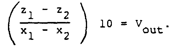
- When the inverting
amplifier 117 is connected as in Figure 18, the circuit functions to produce a percentage as follows: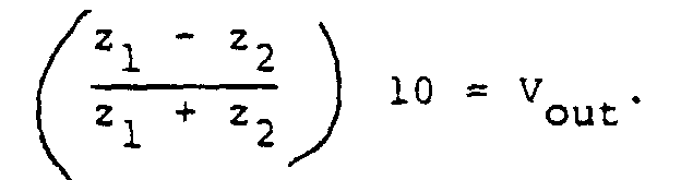
- Returning to Figure 16, in operation, the amplitudes of A and B will be alternately fed to 103 and 105 respectively. A ratio of the differences between A and B is produced at the output of 107. It is important that a ratio be produced so that we are dealing with a figure that is independent of the magnitudes of A and/or B.
- The ratio is then fed to the error amplifier which in turn is fed to the summing
point 113. The second input to the summingpoint 113 is fed with a modulation signal from the control logic 111, and this modulation signal is modified in the summingpoint 113 in accordance with the output of 109. This modulating voltage is then fed to the voltage controlledoscillator 115 which then provides a frequency modulated signal to drive the H1 coil 29. - Although only the use of light radiation sources in optical pumping has been described above, it will be obvious to one skilled in the art that different sources of electromagnetic radiation, e.g., microwave radiation sources, ultraviolet radiation sources, infrared radiation sources, gamma radiation sources, etc. could be used for this purpose, and the term "optically pumped" in the present application could mean a process using any one of the above sources.
- Although several embodiments have been described, this was for the purpose of illustrating, but not limiting, the invention. Various modifications, which will come readily tc the mind of one skilled in the art, are within the scope of the invention as defined in the appended claims.
Claims (26)
- A dead-zone free optically pumped magnetometer, comprising:gas cell means (3) comprising a transparent enclosure means (5, 7);means (29) for forming a multidirectional, A.C. magnetic field H 1 in said enclosure means so that said magnetic field H 1 has no parallel lines of force in the said enclosure means;means (11) for generating a conical beam of resonance radiation such that said radiation is circularly polarized and its rays are multidirectional, non-parallel, in the said enclosure means; anddetector means (25) for detecting said resonance radiation.
- A magnetometer as defined in claim 1, characterized in that said gas cell means (3) comprises a bottom surface (5) and a dome (7) mounted on said bottom surface, said bottom surface (5) and said dome (7) being transparent.
- A magnetometer as defined in claim 2, and further characterized by an H 1 coil (29), for forming said H 1 magnetic field, mounted adjacent said gas cell means (3);a coil driver (33) for activating said H 1 coil (29), said coil driver comprising a voltage controlled square wave or triangular wave generator;said H 1 coil means (29) for forming said multidirectional, A.C. magnetic field H 1 in said enclosure means (5, 7).
- A magnetometer as defined in claim 3, characterized in that said means for generating multidirectional resonance radiation comprises:at least one lamp (11) emitting said resonance radiation; anda first lens arrangement (13) disposed between said lamp and said gas cell means (3).
- A magnetometer as defined in claim 4, characterized in that said resonance radiation comprises light and wherein said detector means (25) comprises:at least one photodetector (25);a second lens arrangement (27) between said gas cell means (3) and said photodetector (25).
- A magnetometer as defined in claim 5, wherein said bottom surface (5) comprises a reflecting mirror (9);light emitted by said lamp (11) being directed at said mirror;whereby, light emitted by said lamp (11) and passing through said gas cell means (3) is reflected by said mirror (9);said photodetector (25) being disposed to receive said reflected light.
- A magnetometer as defined in claim 3, wherein said means for generating resonance radiation comprises:a first lamp (11) for emitting light and a second lamp (11a) for emitting light;a first lens arrangement (13), including a first filter (15) and a first circular polarizer (17), disposed between said first lamp (11) and said gas cell means (3);a second lens arrangement (13a), including a second filter (15a) and a second circular polarizer (17a), disposed between said second lamp (11a) and said gas cell means (3);said detector means (25) comprising a first photodetector (25) and a second photodetector (25a);a third lens arrangement (27) between said gas cell means (3) and said first photodetector (25) and a fourth lens arrangement (27a) between said gas cell means (3) and said second photodetector (25a);said bottom surface comprising said reflecting mirror (9);light emitted by said first and second lamps (11, 11a) being directed at said mirror (9);whereby, light emitted by said lamps and passing through said gas cell means is reflected by said mirror;said first photodetector being disposed to receive reflected light of said first lamp;said second photodetector being disposed to receive reflected light of said second lamp;said first lamp being angularly spaced from said second lamp.
- A magnetometer as defined in claim 2, 3 or 7, wherein said dome (7) is hemispherical.
- A magnetometer as defined in claim 8, wherein said gas cell means (3) is filled with a helium gas or alkali metal vapor and said lamps (11, 11a) are helium gas or alkali metal lamps.
- A magnetometer as defined in claim 8, wherein said gas cell means is filled with a cesium vapor, and said lamps are cesium lamps.
- A magnetometer as defined in claim 4, wherein said first lens arrangement (13) comprises:a first lens assembly (13) spaced between said lamp (11) and said gas cell means in a first direction, said first direction being the direction of travel of resonance radiation emitted from said lamp;said resonance radiation comprises light;a filter (15) and polarizer (17) assembly spaced from said first lens assembly in said first direction;a second lens assembly (19) spaced from said filter and polarizer assembly in said first direction;said gas cell means (3) being spaced from said second lens arrangement in said first direction.
- A magnetometer as defined in claim 11, wherein said first lens assembly comprises a first positive lens (43) comprising an aspheric lens;said second lens assembly comprises a second positive lens (47) comprising an aspheric lens; andsaid detector (25) is a photodetector disposed on the center of said bottom surface (5).
- A magnetometer as defined in claims 11 and 12, wherein said first lens assembly (13) comprises a first plurality of coaxial positive lenses (58, 59 and 61);said second lens assembly (27) comprises a second plurality of coaxial positive lenses (63, 65 and 67);said detector (25) is a photodetector disposed on the center of said bottom surface (5) of the gas cell means (3).
- A magnetometer as defined in claim 11, wherein said first lens assembly (13) comprises a plano convex lens (73);said second lens assembly (27) comprises a plano concave lens (75);a spherical photocell arrangement (73') spaced from said gas cell means (3) in said first direction, said spherical photocell arrangement (73') comprising a plurality of spaced photodetectors on a circle of said photocell arrangement.
- A magnetometer as defined in claim 11, 12, 13 or 14, and being housed in a tubular housing (51) having a floor member (53) and a ceiling member (55).
- A magnetometer as defined in claim 11, 12, 13 or 14, wherein said dome is hemispherical.
- A magnetometer as defined in claim 11, 12, 13 or 14, wherein said dome is hemispherical and wherein said gas cell is filled with a helium or alkali metal vapor and said lamps are helium or alkali metal lamps.
- A magnetometer as defined in claim 14, wherein said dome is hemispherical and is filled with a cesium vapor, and said lamps are cesium lamps.
- A magnetometer as defined in claim 3, wherein said resonance radiation comprises light and wherein said means (11) for generating a conical beam of resonance radiation comprises:a light emitting lamp (11);a first parabolic reflector (69) spaced from said lamp in a first direction comprising the direction of travel of the light emitted from said lamp (11);a second parabolic reflector (71) spaced from said first parabolic reflector in a second direction comprising the direction of travel of light reflected by said first parabolic reflector;said gas cell means (3) being spaced from said second parabolic reflector in said first direction;an interference filter and polarizer assembly (45) disposed between said gas cell means (3) and said lamp (11);said detector means (25) comprising a photodetector disposed on said bottom surface.
- A magnetometer as defined in claim 19, and being housed in a tubular housing (51) having a floor member (53) and a ceiling member (55).
- A magnetometer as defined in claim 19, wherein said dome (7) is hemispherical.
- A magnetometer as defined in claim 19, wherein said dome (7) is hemispherical and wherein said gas cell means (3) is filled with a helium or alkali metal vapor and said lamps (11) are helium or alkali metal lamps.
- A magnetometer as defined in claim 19, wherein said dome (7) is hemispherical and is filled with a cesium vapor, and said lamps (11) are cesium lamps.
- A magnetometer as defined in claim 4, 7, 11, 12, 13, 14 or 19, wherein said dome (7) is hemispheric and said H 1 coil (29) comprises a plurality of turns formed in a circle and mounted adjacent the top of said hemispherical dome (7).
- A magnetometer as defined in claim 4, 7, 11, 12, 13, 14 or 19, wherein said dome (7) is hemispheric and wherein said H 1 coil (29a) is in a beehive shape comprising a plurality of turns along the outer surface of said hemispherical dome (7).
- A magnetometer as defined in claim 4, 7, 11, 12, 13, 14 or 19, wherein said dome (7) is hemispheric and wherein said H 1 coil (29b) comprises a toroidal shape.
Priority Applications (2)
| Application Number | Priority Date | Filing Date | Title |
|---|---|---|---|
| DE69229723T DE69229723D1 (en) | 1992-04-27 | 1992-04-27 | Optically pumped Mz magnetometer without dead area |
| AT92303797T ATE182989T1 (en) | 1992-04-27 | 1992-04-27 | OPTICALLY PUMPED MZ MAGNETOMETER WITHOUT DEAD BAND |
Applications Claiming Priority (1)
| Application Number | Priority Date | Filing Date | Title |
|---|---|---|---|
| US07/682,742 US5227722A (en) | 1991-04-08 | 1991-04-08 | Dead-zone free optically pumped MZ magnetometer |
Publications (2)
| Publication Number | Publication Date |
|---|---|
| EP0575670A1 EP0575670A1 (en) | 1993-12-29 |
| EP0575670B1 true EP0575670B1 (en) | 1999-08-04 |
Family
ID=24740951
Family Applications (1)
| Application Number | Title | Priority Date | Filing Date |
|---|---|---|---|
| EP92303797A Expired - Lifetime EP0575670B1 (en) | 1991-04-08 | 1992-04-27 | Dead-zone free optically pumped Mz magnetometer |
Country Status (3)
| Country | Link |
|---|---|
| US (1) | US5227722A (en) |
| EP (1) | EP0575670B1 (en) |
| CA (1) | CA2042446C (en) |
Families Citing this family (17)
| Publication number | Priority date | Publication date | Assignee | Title |
|---|---|---|---|---|
| DE19928032C2 (en) * | 1999-06-18 | 2001-05-23 | Forschungszentrum Juelich Gmbh | Measuring device for measuring the absolute polarization of alkali atoms and method for operating the measuring device |
| FR2713347B1 (en) * | 1993-12-01 | 1995-12-29 | Commissariat Energie Atomique | Magnetometer with coupled light polarization and radiofrequency field. |
| JP5039452B2 (en) * | 2007-06-27 | 2012-10-03 | 株式会社日立ハイテクノロジーズ | Magnetic field measuring device |
| JP5799553B2 (en) * | 2011-04-01 | 2015-10-28 | セイコーエプソン株式会社 | Magnetic field measuring apparatus, magnetic field measuring system, and magnetic field measuring method |
| JP6299128B2 (en) * | 2013-09-24 | 2018-03-28 | セイコーエプソン株式会社 | Measuring device and magnetic measuring device |
| CN103823245B (en) * | 2013-12-27 | 2017-03-01 | 杭州瑞声海洋仪器有限公司 | Omnidirectional's helium light pump magnetic apparatus |
| JP6202044B2 (en) * | 2015-05-14 | 2017-09-27 | セイコーエプソン株式会社 | Magnetic field measuring device |
| CN106772158B (en) * | 2016-12-09 | 2019-07-12 | 上海通用卫星导航有限公司 | A kind of probe of caesium optical pumped magnetometer |
| US10823790B2 (en) | 2017-05-31 | 2020-11-03 | Northrop Grumman Systems Corporation | Pulsed-beam atomic magnetometer system |
| US10782368B2 (en) | 2017-05-31 | 2020-09-22 | Northrop Grumman Systems Corporation | Pulsed-beam atomic magnetometer system |
| US10809342B2 (en) * | 2017-10-02 | 2020-10-20 | Northrop Grumman Systems Corporation | Calibration of a magnetometer system |
| CN108279390B (en) * | 2017-12-27 | 2020-05-12 | 中国船舶重工集团公司第七一0研究所 | Non-blind area optical pump magnetometer probe |
| US11133117B2 (en) | 2019-05-08 | 2021-09-28 | Northrop Grumman Systems Corporation | Atomic interferometer system |
| US11661845B2 (en) * | 2019-05-10 | 2023-05-30 | Baker Hughes Oilfield Operations Llc | Attenuated total internal reflection optical sensor for obtaining downhole fluid properties |
| RU199631U1 (en) * | 2020-04-30 | 2020-09-10 | Российская Федерация, от имени которой выступает ФОНД ПЕРСПЕКТИВНЫХ ИССЛЕДОВАНИЙ | Quantum Mz magnetometer |
| US11965943B2 (en) | 2022-04-15 | 2024-04-23 | Raytheon Company | Bias field control of total-field optically pumped magnetometers (OPMs) for improved detection |
| US12248041B2 (en) * | 2022-04-20 | 2025-03-11 | Northrop Grumman Systems Corporation | Vapor cell detection system |
Citations (1)
| Publication number | Priority date | Publication date | Assignee | Title |
|---|---|---|---|---|
| US3206671A (en) * | 1962-04-09 | 1965-09-14 | Texas Instruments Inc | Atomic collision influenced gaseous helium-3 quantum resonance magnetometer apparatus |
Family Cites Families (11)
| Publication number | Priority date | Publication date | Assignee | Title |
|---|---|---|---|---|
| NL124969C (en) * | 1960-10-13 | |||
| US3350632A (en) * | 1964-08-25 | 1967-10-31 | Varian Associates | Optically pumped atomic diffusion maser with separate pumping and observation regions |
| FR1517682A (en) * | 1965-08-16 | 1968-03-22 | Centre Nat Rech Scient | Method of slaving a magnetic field to zero value and measuring the field thus compensated in intensity, direction and direction and corresponding apparatus |
| FR1500385A (en) * | 1966-09-23 | 1967-11-03 | Csf | Scattered light sensing optically pumped system |
| US3863144A (en) * | 1973-10-17 | 1975-01-28 | Singer Co | High sensitivity gradient magnetometer |
| US4327327A (en) * | 1980-06-05 | 1982-04-27 | The Singer Company | All-angle gradient magnetometer |
| US4509014A (en) * | 1982-11-23 | 1985-04-02 | The United States Of America As Represented By The Secretary Of The Navy | Nuclear magnetic resonance gyroscope |
| US4544891A (en) * | 1982-11-23 | 1985-10-01 | The United States Of America As Represented By The Secretary Of The Navy | Nuclear magnetic resonance gyroscope |
| US4600886A (en) * | 1983-03-11 | 1986-07-15 | Litton Industries, Inc. | Apparatus for orienting a magnetometer |
| US4567439A (en) * | 1983-09-23 | 1986-01-28 | Texas Instruments Incorporated | Apparatus for measuring the magnitude of a magnetic field |
| FR2663432B1 (en) * | 1990-06-14 | 1992-09-11 | Commissariat Energie Atomique | RESONANCE AND OPTICALLY PUMPED MAGNETOMETER USING A PLURALITY OF MULTIPLEXED BEAMS. |
-
1991
- 1991-04-08 US US07/682,742 patent/US5227722A/en not_active Expired - Lifetime
- 1991-05-13 CA CA002042446A patent/CA2042446C/en not_active Expired - Lifetime
-
1992
- 1992-04-27 EP EP92303797A patent/EP0575670B1/en not_active Expired - Lifetime
Patent Citations (1)
| Publication number | Priority date | Publication date | Assignee | Title |
|---|---|---|---|---|
| US3206671A (en) * | 1962-04-09 | 1965-09-14 | Texas Instruments Inc | Atomic collision influenced gaseous helium-3 quantum resonance magnetometer apparatus |
Also Published As
| Publication number | Publication date |
|---|---|
| US5227722A (en) | 1993-07-13 |
| EP0575670A1 (en) | 1993-12-29 |
| CA2042446C (en) | 1995-05-09 |
Similar Documents
| Publication | Publication Date | Title |
|---|---|---|
| US5227722A (en) | Dead-zone free optically pumped MZ magnetometer | |
| CN110261797B (en) | Optical pump atomic magnetometer based on many Cheng Huanxing optical cavities | |
| US10126377B2 (en) | Magneto-optical defect center magnetometer | |
| US4755027A (en) | Method and device for polarizing light radiation | |
| US12596141B2 (en) | Quantum electromagnetic field sensor | |
| US3335285A (en) | Photoelectric system for detecting objects in a zone including vibrating light source | |
| Penning et al. | Circular polarization in the DQ Herculis binary 3A 0729+ 103 | |
| CN109342980A (en) | Single-light Mx atomic magnetometer based on elliptical light | |
| US4105332A (en) | Apparatus for producing a light beam having a uniform phase front and distance measuring apparatus | |
| CN108318842B (en) | Non-blind area laser optical pump magnetometer probe | |
| WO2022163678A1 (en) | Diamond sensor unit and diamond sensor system | |
| GB1161501A (en) | Measuring Weak Magnetic Fields by Compensation to Zero | |
| CN113625205A (en) | Multichannel atomic magnetic field measuring device | |
| JP3202059B2 (en) | Dead-zone optically excited Mz magnetometer | |
| CN114527413A (en) | Full-polarization regulation and control extremely-weak magnetic field detection device | |
| CN210376655U (en) | Optical pump atomic magnetometer based on multi-pass annular optical cavity | |
| US4505588A (en) | Fiber stellar interferometer | |
| JP2005270304A (en) | Magnetic resonance imaging apparatus and magnetic resonance signal receiver | |
| CN108279390B (en) | Non-blind area optical pump magnetometer probe | |
| CN119087311A (en) | Photoelectric signal conversion system of magnetometer | |
| US5473438A (en) | Spectroscopic method and apparatus for measuring optical radiation | |
| EP0058831B1 (en) | Atomic absorption spectrophotometer providing background correction using the zeeman effect | |
| CN110031425A (en) | Laser gas remote measurement device and laser gas remote measurement method | |
| Sellgren et al. | Search for polarization of the 3.3 and 11.3-micron interstellar emission features | |
| RU2239215C2 (en) | Optical construction of thermovision scanning system |
Legal Events
| Date | Code | Title | Description |
|---|---|---|---|
| PUAI | Public reference made under article 153(3) epc to a published international application that has entered the european phase |
Free format text: ORIGINAL CODE: 0009012 |
|
| AK | Designated contracting states |
Kind code of ref document: A1 Designated state(s): AT BE CH DE DK ES FR GB GR IT LI LU MC NL PT SE |
|
| 17P | Request for examination filed |
Effective date: 19940615 |
|
| 17Q | First examination report despatched |
Effective date: 19960628 |
|
| GRAG | Despatch of communication of intention to grant |
Free format text: ORIGINAL CODE: EPIDOS AGRA |
|
| GRAG | Despatch of communication of intention to grant |
Free format text: ORIGINAL CODE: EPIDOS AGRA |
|
| GRAH | Despatch of communication of intention to grant a patent |
Free format text: ORIGINAL CODE: EPIDOS IGRA |
|
| GRAH | Despatch of communication of intention to grant a patent |
Free format text: ORIGINAL CODE: EPIDOS IGRA |
|
| GRAA | (expected) grant |
Free format text: ORIGINAL CODE: 0009210 |
|
| AK | Designated contracting states |
Kind code of ref document: B1 Designated state(s): AT BE CH DE DK ES FR GB GR IT LI LU MC NL PT SE |
|
| PG25 | Lapsed in a contracting state [announced via postgrant information from national office to epo] |
Ref country code: BE Free format text: LAPSE BECAUSE OF FAILURE TO SUBMIT A TRANSLATION OF THE DESCRIPTION OR TO PAY THE FEE WITHIN THE PRESCRIBED TIME-LIMIT Effective date: 19990804 Ref country code: IT Free format text: LAPSE BECAUSE OF FAILURE TO SUBMIT A TRANSLATION OF THE DESCRIPTION OR TO PAY THE FEE WITHIN THE PRE;WARNING: LAPSES OF ITALIAN PATENTS WITH EFFECTIVE DATE BEFORE 2007 MAY HAVE OCCURRED AT ANY TIME BEFORE 2007. THE CORRECT EFFECTIVE DATE MAY BE DIFFERENT FROM THE ONE RECORDED.SCRIBED TIME-LIMIT Effective date: 19990804 Ref country code: LI Free format text: LAPSE BECAUSE OF FAILURE TO SUBMIT A TRANSLATION OF THE DESCRIPTION OR TO PAY THE FEE WITHIN THE PRESCRIBED TIME-LIMIT Effective date: 19990804 Ref country code: GR Free format text: LAPSE BECAUSE OF NON-PAYMENT OF DUE FEES Effective date: 19990804 Ref country code: CH Free format text: LAPSE BECAUSE OF FAILURE TO SUBMIT A TRANSLATION OF THE DESCRIPTION OR TO PAY THE FEE WITHIN THE PRESCRIBED TIME-LIMIT Effective date: 19990804 Ref country code: NL Free format text: LAPSE BECAUSE OF FAILURE TO SUBMIT A TRANSLATION OF THE DESCRIPTION OR TO PAY THE FEE WITHIN THE PRESCRIBED TIME-LIMIT Effective date: 19990804 Ref country code: SE Free format text: THE PATENT HAS BEEN ANNULLED BY A DECISION OF A NATIONAL AUTHORITY Effective date: 19990804 Ref country code: ES Free format text: THE PATENT HAS BEEN ANNULLED BY A DECISION OF A NATIONAL AUTHORITY Effective date: 19990804 Ref country code: AT Free format text: LAPSE BECAUSE OF FAILURE TO SUBMIT A TRANSLATION OF THE DESCRIPTION OR TO PAY THE FEE WITHIN THE PRESCRIBED TIME-LIMIT Effective date: 19990804 |
|
| REF | Corresponds to: |
Ref document number: 182989 Country of ref document: AT Date of ref document: 19990815 Kind code of ref document: T |
|
| REG | Reference to a national code |
Ref country code: CH Ref legal event code: EP |
|
| REF | Corresponds to: |
Ref document number: 69229723 Country of ref document: DE Date of ref document: 19990909 |
|
| ET | Fr: translation filed | ||
| PG25 | Lapsed in a contracting state [announced via postgrant information from national office to epo] |
Ref country code: PT Free format text: LAPSE BECAUSE OF FAILURE TO SUBMIT A TRANSLATION OF THE DESCRIPTION OR TO PAY THE FEE WITHIN THE PRESCRIBED TIME-LIMIT Effective date: 19991104 Ref country code: DK Free format text: LAPSE BECAUSE OF FAILURE TO SUBMIT A TRANSLATION OF THE DESCRIPTION OR TO PAY THE FEE WITHIN THE PRESCRIBED TIME-LIMIT Effective date: 19991104 |
|
| PG25 | Lapsed in a contracting state [announced via postgrant information from national office to epo] |
Ref country code: DE Free format text: LAPSE BECAUSE OF FAILURE TO SUBMIT A TRANSLATION OF THE DESCRIPTION OR TO PAY THE FEE WITHIN THE PRESCRIBED TIME-LIMIT Effective date: 19991105 |
|
| NLV1 | Nl: lapsed or annulled due to failure to fulfill the requirements of art. 29p and 29m of the patents act | ||
| REG | Reference to a national code |
Ref country code: CH Ref legal event code: PL |
|
| PG25 | Lapsed in a contracting state [announced via postgrant information from national office to epo] |
Ref country code: LU Free format text: LAPSE BECAUSE OF NON-PAYMENT OF DUE FEES Effective date: 20000427 |
|
| PLBE | No opposition filed within time limit |
Free format text: ORIGINAL CODE: 0009261 |
|
| STAA | Information on the status of an ep patent application or granted ep patent |
Free format text: STATUS: NO OPPOSITION FILED WITHIN TIME LIMIT |
|
| 26N | No opposition filed | ||
| PG25 | Lapsed in a contracting state [announced via postgrant information from national office to epo] |
Ref country code: MC Free format text: LAPSE BECAUSE OF NON-PAYMENT OF DUE FEES Effective date: 20001031 |
|
| REG | Reference to a national code |
Ref country code: GB Ref legal event code: IF02 |
|
| PGFP | Annual fee paid to national office [announced via postgrant information from national office to epo] |
Ref country code: FR Payment date: 20110511 Year of fee payment: 20 |
|
| PGFP | Annual fee paid to national office [announced via postgrant information from national office to epo] |
Ref country code: GB Payment date: 20110426 Year of fee payment: 20 |
|
| REG | Reference to a national code |
Ref country code: GB Ref legal event code: PE20 Expiry date: 20120426 |
|
| PG25 | Lapsed in a contracting state [announced via postgrant information from national office to epo] |
Ref country code: GB Free format text: LAPSE BECAUSE OF EXPIRATION OF PROTECTION Effective date: 20120426 |