EP0575523B1 - Flow regulator adaptable for use with exhaust from a process chamber - Google Patents
Flow regulator adaptable for use with exhaust from a process chamber Download PDFInfo
- Publication number
- EP0575523B1 EP0575523B1 EP92908728A EP92908728A EP0575523B1 EP 0575523 B1 EP0575523 B1 EP 0575523B1 EP 92908728 A EP92908728 A EP 92908728A EP 92908728 A EP92908728 A EP 92908728A EP 0575523 B1 EP0575523 B1 EP 0575523B1
- Authority
- EP
- European Patent Office
- Prior art keywords
- piston
- fluid
- flow
- conduit
- portions
- Prior art date
- Legal status (The legal status is an assumption and is not a legal conclusion. Google has not performed a legal analysis and makes no representation as to the accuracy of the status listed.)
- Expired - Lifetime
Links
Images


Classifications
-
- G—PHYSICS
- G05—CONTROLLING; REGULATING
- G05D—SYSTEMS FOR CONTROLLING OR REGULATING NON-ELECTRIC VARIABLES
- G05D7/00—Control of flow
- G05D7/06—Control of flow characterised by the use of electric means
- G05D7/0617—Control of flow characterised by the use of electric means specially adapted for fluid materials
- G05D7/0629—Control of flow characterised by the use of electric means specially adapted for fluid materials characterised by the type of regulator means
- G05D7/0635—Control of flow characterised by the use of electric means specially adapted for fluid materials characterised by the type of regulator means by action on throttling means
-
- F—MECHANICAL ENGINEERING; LIGHTING; HEATING; WEAPONS; BLASTING
- F24—HEATING; RANGES; VENTILATING
- F24F—AIR-CONDITIONING; AIR-HUMIDIFICATION; VENTILATION; USE OF AIR CURRENTS FOR SCREENING
- F24F11/00—Control or safety arrangements
- F24F11/70—Control systems characterised by their outputs; Constructional details thereof
- F24F11/72—Control systems characterised by their outputs; Constructional details thereof for controlling the supply of treated air, e.g. its pressure
- F24F11/74—Control systems characterised by their outputs; Constructional details thereof for controlling the supply of treated air, e.g. its pressure for controlling air flow rate or air velocity
- F24F11/75—Control systems characterised by their outputs; Constructional details thereof for controlling the supply of treated air, e.g. its pressure for controlling air flow rate or air velocity for maintaining constant air flow rate or air velocity
-
- F—MECHANICAL ENGINEERING; LIGHTING; HEATING; WEAPONS; BLASTING
- F24—HEATING; RANGES; VENTILATING
- F24F—AIR-CONDITIONING; AIR-HUMIDIFICATION; VENTILATION; USE OF AIR CURRENTS FOR SCREENING
- F24F3/00—Air-conditioning systems in which conditioned primary air is supplied from one or more central stations to distributing units in the rooms or spaces where it may receive secondary treatment; Apparatus specially designed for such systems
- F24F3/12—Air-conditioning systems in which conditioned primary air is supplied from one or more central stations to distributing units in the rooms or spaces where it may receive secondary treatment; Apparatus specially designed for such systems characterised by the treatment of the air otherwise than by heating and cooling
- F24F3/16—Air-conditioning systems in which conditioned primary air is supplied from one or more central stations to distributing units in the rooms or spaces where it may receive secondary treatment; Apparatus specially designed for such systems characterised by the treatment of the air otherwise than by heating and cooling by purification, e.g. by filtering; by sterilisation; by ozonisation
- F24F3/167—Clean rooms, i.e. enclosed spaces in which a uniform flow of filtered air is distributed
Definitions
- This invention generally relates to a device for regulating the flow of a fluid, in particular a gas, through the device.
- HVAC heating, ventilating, and air conditioning
- resistors may be comprised of gate valves, butterfly valves or dampers, and may be fixed, adjustable or motorized.
- the pressure level throughout the HVAC system will change; any change in the HVAC system pressure will affect the flow of air past every other resistor.
- adjusting a resistor at the output causes "cross-talk.”
- Gas companies have safety valves that shut off the flow of gas when there is a large decrease in pressure, since such a decrease may be due to a leak downstream of the valve.
- Many safety valves vent fluid from a conduit when there is a large increase in pressure in order to prevent the pressure in the conduit from increasing beyond the bursting point of the conduit, or beyond the capability of machinery connected to the conduit.
- Other valves such as those used in gasoline pumps, also shut off flow automatically when the backpressure increases to a certain point, indicating that the tank being filled is full.
- These safety valves and gasoline-pump valves are designed to be either fully opened or fully closed, and are not designed to precisely regulate the fluid flow.
- USA 3053272 discloses a vacuum regulator incorporated into an automatic milking system.
- the regulator maintains the vacuum in the system at a relatively uniform level even though the load on the system may change and includes a displaceable piston whose position is governed by the relative pressures acting on either face of the piston.
- USA 3978883 discloses a device for regulating the combustion air of a furnace in order to supply a constant volume of air per unit time.
- the device includes a displaceable throttle element whose position is varied by means of bellows according to the relative pressures acting on either face of the bellows.
- USA 3312241 discloses a fluid control valve to control the flow of pressurised fluid such as steam which is to be fed to turbine units.
- Moveable grid members which are used to block the flow of fluid are displaced by hydraulic means and are biased in the closed position so that hydraulic pressure is necessary to enable the flow of fluid through the valve.
- a device for regulating the flow of fluid through a conduit wherein the device includes impedance means for variably impeding the flow of fluid through the conduit and restoring means operably linked to the impedance means, wherein the impedance means comprises a displaceable piston having a distal face which is exposed to a reference pressure and a frontal face which forms a part of the wall of the conduit so that the impedance to the flow of fluid through the conduit varies as a function of the position of the displaceable piston, and wherein the restoring means is adapted to displace the piston so that the impedance to the flow of fluid through the conduit is reduced, characterised in that the piston is pivotally mounted so as to rotate about a hinge point.
- the present invention solves the problems found in the prior art systems by providing a self-regulating flow control system. Compared to many of the prior art systems, the present invention is not complex and imparts very little resistance to flow during low flow situations.
- the regulator includes a movably mounted piston having a distal face, exposed to a reference pressure, and a frontal face, exposed to fluid passing through the regulator.
- the path of fluid passing through the regulator is substantially straight. It is also preferred that the regulator not be vented at any point between the input and output of the regulator, so that the mass of fluid exiting the regulator is the same as the mass entering the regulator.
- Attached to the piston is a member that variably impedes fluid flowing through the regulator.
- the amount that this member impedes the fluid flow varies as a function of the difference between the pressure of fluid on the frontal face of the piston and the reference pressure.
- This member may be an integral part of the piston extending into the path of the fluid flowing through the regulator, or it may be a separate member attached to the piston.
- this impeding member includes an airfoil segment or several such segments.
- Each airfoil segment that is movable and attached to the piston has a corresponding airfoil segment that is not movable, so that there are pairs of airfoil segments--each pair having a movable segment and a fixed segment, and each pair forming a complete airfoil.
- each movable segment is displaced with respect to its corresponding fixed segment.
- the impedance to flow increases.
- the piston may be hingedly mounted.
- the movable airfoil segments may also be hingedly attached to the piston.
- a restoring force exerts a force on the piston so as to tend to lessen the resistance on the fluid flow, and so that when there is no flow through the passageway the resistance is relatively low.
- the restoring force includes the weight of the piston.
- a spring may be used to apply or adjust the restoring force.
- the piston and the impeding member are mounted so as to move in a direction transverse to the direction of fluid flowing past the frontal face of the piston. It is also preferable that the impeding member is mounted downstream of the frontal face of the piston.
- a variable resistance valve is located upstream of the frontal face of the piston, and the reference pressure is the pressure of fluid upstream of the variable resistance means.
- the reference pressure may be the same as the environment that the fluid flows from, or alternatively it may be the same as the pressure somewhere else upstream of the piston or the variable resistance valve.
- a venturi is disposed in the fluid path. At least part of the venturi is formed with the frontal face of a piston.
- the piston is movably mounted so that it may move transversely to the flow through the path, and so that as the velocity of the fluid flowing through the path increases, the difference between the reference pressure and the pressure in the venturi increases causing the piston to move in a direction narrowing the venturi.
- a restoring force is exerted on the piston in the direction that tends to move the piston so as to widen the venturi.
- Figs. 1, 2, 3 and 4 show cross-sections of several regulators according to the invention.
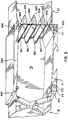
- Fig. 5 shows a perspective view of a regulator that is an embodiment of the invention having several airfoils, wherein the near wall of the regulator has been removed to expose the interior of the regulator.
- Fig. 6 shows a cross-section of the regulator shown in Fig. 5.
- Figs. 7A and 7B show a cross-section of a portion of the regulator shown in Fig. 5; in Fig. 7A there is little or no flow through the regulator, and in Fig. 7B there is a greater flow.
- Fig. 8 shows a perspective view of the exterior of the regulator shown in Fig. 5.
- Fig. 9 shows how regulators according to the invention may be employed in regulating flow through a process chamber.
- Fig. 1 shows a mass flow regulator according to the present invention.
- Air flows from the input 81 , past a variable resistor, which in this case is a gate valve 95 , into a chamber, called the plenum 79 . Air moves over the frontal face 52 of the piston 5 .
- the air flow is then modulated by constriction point 80 , which is formed by the upturned section 96 at the end of piston 5 .
- the piston 5 rotates about hinge 84 , so that member 96 moves in a direction transverse to the air flow.
- the output 82 is connected to a vacuum source, but in any case the pressure at the output 82 must be lower than the pressure at the input 81 .
- the pressure in the plenum 79 is related to the fluid forces on the frontal and distal faces, 52 and 51 , of the piston 5 , and the restoring force on the piston 5 .
- the downward restoring force is caused by the weight of the piston 5 .
- Restoring force may also be supplied or modified by a spring, and/or, as shown in Fig. 4 below, by a slidable weight.
- the restoring force tends to open the constriction point 80 .
- the restoring force balances the force caused by the pressure differential between the plenum 79 , through which the air flows, and the reference-pressure chamber 17 (which should have a higher pressure than the plenum 79 does), so that the piston 5 floats.
- the chamber 17 is in fluid communication with the reference port 85 , which may be connected to the environment from which fluid flows to the input 81 .
- the plenum 79 acts as a constant vacuum sink drawing in fluid flowing from input 81 past the gate valve 95, which acts as a resistor. If the differential pressure between input 81 and plenum 79 remains constant, and the resistance to flow between input 81 and plenum 79 remains constant, the fluid mass flow rate will remain constant. The mass flow rate may be changed by changing the resistance to fluid flow caused by the gate valve 95 .
- a constant pressure differential between the input 81 and the plenum 79 can be maintained by venting the reference chamber 17 to the input 81 , which is accomplished by connecting reference port 85 to the input 81 .
- Adjusting the gate valve 95 causes more or less fluid to flow into plenum 79 , and the piston 5 and impeding member 96 will move down or up to modulate the pressure in the plenum 79 .
- a change in the input pressure will cause a corresponding change in the pressure of chamber 17 , which in turn will cause the piston 5 to move and either widen or narrow the constriction point 80 to maintain a constant pressure differential between the plenum 79 and the input 81 .
- variable resistor 95 By combining variable resistor 95 with a regulator that maintains a constant pressure differential across the variable resistor 95 , the device shown in Fig. 1 performs very well as a mass flow controller.
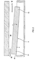
- Fig. 2 shows another embodiment of the invention.
- a venturi 80 which is formed in part by the top (frontal) face 52 of the piston 5 , does not gradually widen as the venturis shown in Figs. 3 and 4 below.
- the port 85 in this version is located at the output 82 of the device.
- the piston is pivotally mounted at one end 53 , while the other end 54 constricts the flow of fluid.
- Fig. 3 shows another mass flow regulator.
- fluid flows from the input 81 , through a venturi valve 80 that gradually narrows and widens the fluid passageway, to an output 82 .
- Part of the venturi is made of a movable piston 5 , which may move up to narrow the venturi or move down to widen the venturi.
- the piston 5 is attached to the body of the device by a hinge 84 located near the output 82 of the device.
- the lower face of the piston 5 is exposed to a chamber 17 having a reference pressure.
- This chamber 17 is vented to the input 81 by means of a port 85 , such that the reference pressure is equal to the pressure of the fluid at the input 81 .
- the pressure in the venturi decreases because of the Bernoulli effect. This causes the piston 5 to tend to move up to narrow the venturi.
- the weight of the piston 5 tends to pull the piston downward.
- Another means of exerting a restoring force on the piston 5 would be with a spring.
- the force exerted by the weight of the piston, or other restoring force balances with the force caused by the pressure differential between the chamber 17 and the venturi 80 , causing the piston to float (assuming the velocity of the fluid is great enough).
- the pressure in the venturi, 80 will further decrease causing the piston to rise further.
- the cross-sectional area of the venturi 80 decreases.
- the mass flow rate of the fluid is equal to the product of the fluid's density, the cross-sectional area of the pathway and the velocity of the fluid, the mass flow rate remains fairly constant, i.e., the increased velocity is offset by the decreased cross-sectional area.
- Fig. 4 shows a modified version of the Fig. 3 device, wherein the device can be adjusted to attain various mass flow rates. This is done by using a slidable mass 90 .
- the desired mass flow rate can be increased by moving the mass 90 to the left, or decreased by moving the mass to the right.
- the movement of the mass can, of course, be accomplished manually; however, it can also be accomplished remotely by using a servo-motor 92 which can move the mass 90 back and forth. The servo-motor can then be controlled electrically.
- Figs. 5 and 6 are different perspectives of a preferred embodiment of the invention that has three airfoils 965 mounted in the path of the air flow.
- the airfoils 965 are divided into upstream segments 961 and downstream segments 964 .
- the upstream segments 961 in this embodiment are movable, whereas the downstream segments 964 are fixed to the walls of the fluid conduit.
- the upstream segments 961 are rigidly attached to each other by rods 967 and 968 , which in turn are hingedly attached at their lower ends to piston 5 at hinge point 845 .
- the piston 5 in this device like the pistons of the devices shown in Figs. 1-4, is hingedly mounted so that it rotates about point 84 .
- rods 967 and 968 are also hingedly attached at hinge point 846 to upper member 843 , which in turn is hingedly mounted so that it rotates about point 842 . Because of these hinge connections, 84, 842, 845 and 846 , the upper member 843 moves in parallel with piston 5 . From the perspective shown in Fig. 6, the piston 5 , the upper member 843 and the rods 967 and 968 appear as three sides of a parallelogram with varying angles.
- the piston 5 in the device shown in Figs. 5 and 6 is like the pistons shown in Figs. 1-4 in most respects.
- the frontal face 52 of the piston 5 is exposed to the air in the plenum 79
- its distal face 51 is exposed to air in the reference chamber 17 , and pivots up and down depending on the pressure differential between the plenum 79 and the reference chamber 17 .
- air flowing through the device is more or less constricted.
- the reference chamber 17 has flexible membranes 171 and 172 mounted at its edges to prevent an undue amount of air from flowing from the reference chamber 17 around the hinge points 84 and 845 into the plenum 79 , which is normally at a lower pressure than the reference pressure when fluid is flowing through the device.
- Figs. 7A and 7B show how the upstream segments 961 are displaced with respect to downstream segments 964, so as to narrow the constriction points 80 .
- rods 967 and 968 rod 968 is not shown in Figs. 7A and 7B
- the downstream segments 964 are fixedly attached to the walls of the conduit and thus do not move. As segments 961 and 964 are displaced with respect to each other, the constriction points 80 narrow, and the impedance on the air flow increases.
- the upstream segments 961 are fixedly attached to the conduit walls and the downstream segments 964 are attached to the piston 5 by means of rods 967 and 968 .
- the effect on fluid flow in this alternative embodiment is similar to that of the embodiment shown in Figs. 5, 6, 7A and 7B: when the piston 5 rises, the airfoil segments 961 and 964 are displaced with respect to each other, and the constriction points 80 are narrowed.
- each airfoil may be divided into three segments, upstream, middle and downstream segments, wherein the upstream and downstream segments are fixedly attached to the conduit walls, and the middle segment is movable.
- some smaller portion of each airfoil may be displaceable from the rest of the airfoil so as to extend from the top of the airfoil and occlude the constriction point above the airfoil.
- the restoring force created by the weight of the piston may be modified in a manner similar to that shown in the flow regulator shown in Fig. 4, which uses a slidable mass 90 .
- a guide arm 91 along which the mass is slid, may be attached to the extension 841 (shown in Fig. 5) at the pivot point 84 .
- the mass 90 may be moved closer to or further from the pivot point 84 in order to alter the tendency of the piston 5 to move up or down.
- the mass 90 is positioned by means of a servo-motor, which is controlled electrically from a remote location.
- This slidable mass apparatus may be located in a housing 849 located on the side of the regulator, as seen in Fig. 8.
- Fig. 8 shows the exterior of the regulator shown in Figs. 5 and 6.
- airfoils as a way of impeding flow may be adapted for use in a device for regulating flow from a air source to a process chamber at a lower pressure.
- the air foils are mounted upstream of the plenum.
- the piston is hingedly mounted over the plenum, so that, as the pressure in the plenum increases with respect to the reference (process chamber) pressure, the piston lifts a portion of the air foils, thereby increasing the impedance to the airfoil.
- Fig. 9 shows how the regulators described hereinabove may be used to control the flow of air from a process chamber.
- Air enters the process chamber through one or more regulators 97 .
- the regulator shown in Figs. 5 and 6 in the present application may be used as regulator 98 in the Fig. 9 system.
- the reference chamber 17 is connected to the process chamber so that the pressure in the process chamber is the reference pressure.
- the input 81 of the regulator 98 is attached to the fume hood 94 , which draws noxious fumes.
- the regulator 98 maintains in the fume hood 94 a fairly constant vacuum relative to the process chamber (i.e., a lower pressure than the process chamber). Fume hoods frequently have doors that allow laboratory technicians access inside the fume hood 94 . When these doors are opened, the regulator 98 controlling the relative vacuum in the fume hood 94 increases the air flow through the fume hood, thereby maintaining the vacuum in the fume hood 94 .
- Regulator 99 draws air directly from the process chamber, preferably at a constant mass flow rate.
- the regulator shown in Fig. 1 which has a gate valve 95 mounted upstream of the piston 5 , may be used to control the mass flow rate.
- the regulator shown in Figs. 5 and 6 may be used to control the mass flow rate, if a throttling valve, such as gate valve 95 of the Fig. 1 regulator, is placed upstream of the piston 5 .
- the regulators shown in Figs. 2, 3 and 4 of the present application may also be used as the mass flow regulator 99 of the Fig. 9 system.
Abstract
Description
Claims (15)
- A device for regulating the flow of fluid through a conduit, wherein the device includes impedance means (54)(96)(961) for variably impeding the flow of fluid through the conduit and restoring means (90) operably linked to the impedance means (54)(96)(961), wherein the impedance means (54)(96)(961) comprises a displaceable piston (5) having a distal face (51) which is exposed to a reference pressure and a frontal face (52) which forms a part of the wall of the conduit so that the impedance to the flow of fluid through the conduit varies as a function of the position of the displaceable piston (5), and wherein the restoring means (90) is adapted to displace the piston (5) so that the impedance to the flow of fluid through the conduit is reduced, characterised in that the piston (5) is pivotally mounted so as to rotate about a hinge point (84).
- A device as claimed in claim 1, wherein the piston (5) is mounted so as to move in a direction substantially transverse to the direction of flow of fluid across the frontal face (52) of the piston (5) thereby widening or narrowing the conduit.
- A device as claimed in claim 1 or 2, wherein the conduit is in communication with an environment, and the reference pressure is the pressure of the environment.
- A device as claimed in claim 1, 2 or 3, further including variable resistance means (95) for variably impeding the flow of fluid into the conduit.
- A device as claimed in claim 4, wherein the variable resistance means (95) is located upstream of the frontal face (52) of the piston (5), and wherein the reference pressure is the pressure of fluid upstream of the variable resistance means (95).
- A device as claimed in any preceding claim, wherein the restoring means (90) includes the weight of the piston (5).
- A device as claimed in any preceding claim, wherein the piston (5) includes a slidable weight (90) which may be moved towards or away from the hinge point (84) so as to vary the force exerted by the restoring means.
- A device as claimed in any preceding claim, wherein the frontal (52) and distal (51) faces have approximately equal areas.
- A device as claimed in any preceding claim, wherein the conduit is not vented at any point between the input (81) and the output (82) of the conduit so that the mass of fluid exiting the device through the output (82) is substantially equal to the mass of fluid entering the device through the input (81).
- A device as claimed in any preceding claim wherein the piston (5) includes a lip (80) at the downstream end of the frontal face (52).
- A device as claimed in any of claims 1 to 9, wherein the piston (5) includes one or more first portions (961) which on displacement of the piston (5) are displaced with respect to one or more corresponding second portions (964) so that the greater the relative displacement of the or each corresponding first (961) and second (964) portions the greater the impedance to the flow of fluid through the conduit.
- A device as claimed in any of claims 1 to 9, wherein the piston (5) includes one or more first portions and one or more third portions, the or each first and third portions corresponding with the or each second portions, so that on displacement of the piston (5) the or each first and third portions are displaced with respect to the or each corresponding second portions so that the greater the relative displacement of the or each first and third portions with respect to the or each corresponding second portions the greater the impedance to the flow of fluid through the conduit.
- A device as claimed in claim 11 or 12 wherein the first (961) and second (964) portions, or wherein the first, second and third portions, constitute an airfoil when the first and second, or first, second and third portions are aligned so as to correspond with one another.
- A device as claimed in claim 11 wherein the first portion (961) is hingedly attached to the piston (5).
- A device as claimed in claim 11 or 12, wherein the first portion (961) is upstream and the second portion (964) is downstream with respect to the direction of flow of the fluid through the conduit.
Applications Claiming Priority (3)
| Application Number | Priority Date | Filing Date | Title |
|---|---|---|---|
| US66974691A | 1991-03-15 | 1991-03-15 | |
| US669746 | 1991-03-15 | ||
| PCT/US1992/002013 WO1992016884A1 (en) | 1991-03-15 | 1992-03-13 | Flow regulator adaptable for use with exhaust from a process chamber |
Publications (3)
| Publication Number | Publication Date |
|---|---|
| EP0575523A1 EP0575523A1 (en) | 1993-12-29 |
| EP0575523A4 EP0575523A4 (en) | 1995-04-19 |
| EP0575523B1 true EP0575523B1 (en) | 1998-07-15 |
Family
ID=24687558
Family Applications (4)
| Application Number | Title | Priority Date | Filing Date |
|---|---|---|---|
| EP92908728A Expired - Lifetime EP0575523B1 (en) | 1991-03-15 | 1992-03-13 | Flow regulator adaptable for use with exhaust from a process chamber |
| EP01116749A Expired - Lifetime EP1174783B1 (en) | 1991-03-15 | 1992-03-13 | Process-chamber flow control system |
| EP98100282A Expired - Lifetime EP0853266B1 (en) | 1991-03-15 | 1992-03-13 | Process-chamber flow control system |
| EP92908979A Expired - Lifetime EP0575533B1 (en) | 1991-03-15 | 1992-03-13 | Process-chamber flow control system |
Family Applications After (3)
| Application Number | Title | Priority Date | Filing Date |
|---|---|---|---|
| EP01116749A Expired - Lifetime EP1174783B1 (en) | 1991-03-15 | 1992-03-13 | Process-chamber flow control system |
| EP98100282A Expired - Lifetime EP0853266B1 (en) | 1991-03-15 | 1992-03-13 | Process-chamber flow control system |
| EP92908979A Expired - Lifetime EP0575533B1 (en) | 1991-03-15 | 1992-03-13 | Process-chamber flow control system |
Country Status (8)
| Country | Link |
|---|---|
| EP (4) | EP0575523B1 (en) |
| JP (2) | JP3256228B2 (en) |
| KR (2) | KR100202432B1 (en) |
| AT (4) | ATE212735T1 (en) |
| CA (2) | CA2106186C (en) |
| DE (4) | DE69233645T2 (en) |
| DK (1) | DK1174783T3 (en) |
| WO (4) | WO1992016883A1 (en) |
Families Citing this family (7)
| Publication number | Priority date | Publication date | Assignee | Title |
|---|---|---|---|---|
| US5320124A (en) * | 1988-04-07 | 1994-06-14 | Palmer David W | Regulator adaptable for maintaining a constant partial vacuum in a remote region |
| US5450873A (en) * | 1988-04-07 | 1995-09-19 | Palmer; David W. | System for controlling flow through a process region |
| US5655562A (en) * | 1988-04-07 | 1997-08-12 | Palmer; David W. | System for controlling flow through a process region |
| DE19537063C2 (en) * | 1995-10-05 | 2001-01-25 | Klaus Beck | Volume flow controller |
| SE521968C2 (en) * | 2000-05-22 | 2003-12-23 | Scania Cv Ab | Method and apparatus for exhaust gas recirculation in an internal combustion engine and such engine |
| FR2824645B1 (en) * | 2001-05-11 | 2004-02-13 | Claude Jean Marie Frangin | FLUID REGULATOR |
| CN113110627B (en) * | 2021-04-28 | 2022-05-17 | 北京航空航天大学 | High-precision, high-reliability and quick-response adjustable venturi |
Family Cites Families (20)
| Publication number | Priority date | Publication date | Assignee | Title |
|---|---|---|---|---|
| US2899973A (en) * | 1959-08-18 | Pressure reducing valve | ||
| US500221A (en) * | 1893-06-27 | Scrubbing and mopping machine | ||
| US2803261A (en) * | 1953-02-02 | 1957-08-20 | Westinghouse Electric Corp | Velocity responsive controls |
| US3053272A (en) * | 1960-11-16 | 1962-09-11 | Babson Bros Co | Vacuum regulator |
| US3312241A (en) * | 1964-04-16 | 1967-04-04 | Westinghouse Electric Corp | Fluid control apparatus |
| US3853143A (en) * | 1971-01-29 | 1974-12-10 | Danfoss As | Flexible diaphragm air damper |
| US3703913A (en) * | 1971-08-02 | 1972-11-28 | Cvc Co | Automatic rate of flow control valve |
| US3742972A (en) * | 1972-01-03 | 1973-07-03 | Textron Inc | Twin regulator arrangement |
| CH551043A (en) * | 1972-01-28 | 1974-06-28 | Danfoss As | DEVICE RESPONDING TO PRESSURE DIFFERENCES FOR INFLUENCING THE FLOW OF GAS MEDIA IN PLANES. |
| DK136125B (en) * | 1973-02-06 | 1977-08-15 | Danfoss As | Airflow regulator. |
| US3820556A (en) * | 1973-05-11 | 1974-06-28 | Parker Hannifin Corp | Fluid flow control system |
| US3862644A (en) * | 1973-07-12 | 1975-01-28 | United Aircraft Corp | Flow control |
| US3900045A (en) * | 1973-09-27 | 1975-08-19 | Robertshaw Controls Co | Fulcrum pressure regulator |
| DE2421873C2 (en) * | 1974-05-06 | 1983-11-03 | Danfoss A/S, 6430 Nordborg | Device for regulating the combustion air supply to a furnace with oil or gas burners for heating systems |
| SE396250B (en) * | 1975-04-29 | 1977-09-12 | Stifab Ab | CONTROLLER DEVICE INTENDED NOT TO BE IN A FLUID CIRCUIT, FOR EXAMPLE AIR FLOW CURRENT |
| FR2389933B1 (en) * | 1977-05-06 | 1980-04-11 | Lezier Pierre | |
| JPS5471432A (en) * | 1977-11-17 | 1979-06-08 | Sotokazu Rikuta | Flow rate constant value automatic control valve |
| US4428529A (en) * | 1982-07-26 | 1984-01-31 | Honeywell Inc. | Flow synchronization |
| US4873873A (en) * | 1988-02-01 | 1989-10-17 | James L. Day Co., Inc. | Air flow metering terminal and control system |
| US5000221A (en) * | 1989-09-11 | 1991-03-19 | Palmer David W | Flow control system |
-
1992
- 1992-03-13 KR KR1019930702740A patent/KR100202432B1/en not_active IP Right Cessation
- 1992-03-13 EP EP92908728A patent/EP0575523B1/en not_active Expired - Lifetime
- 1992-03-13 AT AT98100282T patent/ATE212735T1/en not_active IP Right Cessation
- 1992-03-13 WO PCT/US1992/002012 patent/WO1992016883A1/en active IP Right Grant
- 1992-03-13 WO PCT/US1992/002011 patent/WO1992016882A1/en active Application Filing
- 1992-03-13 AT AT92908728T patent/ATE168479T1/en not_active IP Right Cessation
- 1992-03-13 JP JP50788192A patent/JP3256228B2/en not_active Expired - Fee Related
- 1992-03-13 JP JP4508795A patent/JP3014143B2/en not_active Expired - Lifetime
- 1992-03-13 WO PCT/US1992/002013 patent/WO1992016884A1/en active IP Right Grant
- 1992-03-13 KR KR1019930702741A patent/KR100202431B1/en not_active IP Right Cessation
- 1992-03-13 AT AT92908979T patent/ATE168480T1/en not_active IP Right Cessation
- 1992-03-13 CA CA002106186A patent/CA2106186C/en not_active Expired - Fee Related
- 1992-03-13 EP EP01116749A patent/EP1174783B1/en not_active Expired - Lifetime
- 1992-03-13 DE DE69233645T patent/DE69233645T2/en not_active Expired - Fee Related
- 1992-03-13 EP EP98100282A patent/EP0853266B1/en not_active Expired - Lifetime
- 1992-03-13 CA CA002106187A patent/CA2106187C/en not_active Expired - Fee Related
- 1992-03-13 DE DE69226264T patent/DE69226264T2/en not_active Expired - Fee Related
- 1992-03-13 AT AT01116749T patent/ATE336033T1/en not_active IP Right Cessation
- 1992-03-13 EP EP92908979A patent/EP0575533B1/en not_active Expired - Lifetime
- 1992-03-13 DE DE69226265T patent/DE69226265T2/en not_active Expired - Fee Related
- 1992-03-13 WO PCT/US1992/002019 patent/WO1992016885A1/en active Application Filing
- 1992-03-13 DK DK01116749T patent/DK1174783T3/en active
- 1992-03-13 DE DE69232399T patent/DE69232399T2/en not_active Expired - Fee Related
Also Published As
Similar Documents
| Publication | Publication Date | Title |
|---|---|---|
| US5251654A (en) | Flow regulator adaptable for use with exhaust from a process chamber | |
| US5456280A (en) | Process-chamber flow control system | |
| EP0575523B1 (en) | Flow regulator adaptable for use with exhaust from a process chamber | |
| EP0667006B1 (en) | Remote region vacuum regulator | |
| US3976244A (en) | Adjustable air volume regulator having thermal motor actuator for effecting adjustment | |
| US5255710A (en) | Process-chamber flow control system | |
| US5255709A (en) | Flow regulator adaptable for use with process-chamber air filter | |
| US3967642A (en) | Air volume regulator for air conditioning systems | |
| US5634490A (en) | Process-chamber flow control system | |
| JP2922952B2 (en) | Fluid flow regulation device | |
| US4627569A (en) | Four function pneumatic controller | |
| US5597011A (en) | Flow regulator | |
| US5687760A (en) | Flow regulator | |
| USRE36637E (en) | Flow regulator | |
| WO1994010618A1 (en) | System for controlling flow through a process region | |
| US4467956A (en) | System for supplying conditioned air, thermostat therefor and methods of making the same |
Legal Events
| Date | Code | Title | Description |
|---|---|---|---|
| PUAI | Public reference made under article 153(3) epc to a published international application that has entered the european phase |
Free format text: ORIGINAL CODE: 0009012 |
|
| 17P | Request for examination filed |
Effective date: 19930923 |
|
| AK | Designated contracting states |
Kind code of ref document: A1 Designated state(s): AT BE CH DE DK ES FR GB GR IT LI LU MC NL SE |
|
| A4 | Supplementary search report drawn up and despatched | ||
| AK | Designated contracting states |
Kind code of ref document: A4 Designated state(s): AT BE CH DE DK ES FR GB GR IT LI LU MC NL SE |
|
| 17Q | First examination report despatched |
Effective date: 19960430 |
|
| GRAG | Despatch of communication of intention to grant |
Free format text: ORIGINAL CODE: EPIDOS AGRA |
|
| GRAG | Despatch of communication of intention to grant |
Free format text: ORIGINAL CODE: EPIDOS AGRA |
|
| GRAH | Despatch of communication of intention to grant a patent |
Free format text: ORIGINAL CODE: EPIDOS IGRA |
|
| GRAH | Despatch of communication of intention to grant a patent |
Free format text: ORIGINAL CODE: EPIDOS IGRA |
|
| GRAA | (expected) grant |
Free format text: ORIGINAL CODE: 0009210 |
|
| AK | Designated contracting states |
Kind code of ref document: B1 Designated state(s): AT BE CH DE DK ES FR GB GR IT LI LU MC NL SE |
|
| PG25 | Lapsed in a contracting state [announced via postgrant information from national office to epo] |
Ref country code: GR Free format text: LAPSE BECAUSE OF NON-PAYMENT OF DUE FEES Effective date: 19980715 Ref country code: ES Free format text: THE PATENT HAS BEEN ANNULLED BY A DECISION OF A NATIONAL AUTHORITY Effective date: 19980715 |
|
| REF | Corresponds to: |
Ref document number: 168479 Country of ref document: AT Date of ref document: 19980815 Kind code of ref document: T |
|
| REG | Reference to a national code |
Ref country code: CH Ref legal event code: NV Representative=s name: DR. LUSUARDI AG Ref country code: CH Ref legal event code: EP |
|
| ET | Fr: translation filed | ||
| REF | Corresponds to: |
Ref document number: 69226264 Country of ref document: DE Date of ref document: 19980820 |
|
| ITF | It: translation for a ep patent filed |
Owner name: BARZANO'E ZANARDO S.P.A. |
|
| PG25 | Lapsed in a contracting state [announced via postgrant information from national office to epo] |
Ref country code: DK Free format text: LAPSE BECAUSE OF FAILURE TO SUBMIT A TRANSLATION OF THE DESCRIPTION OR TO PAY THE FEE WITHIN THE PRESCRIBED TIME-LIMIT Effective date: 19981015 |
|
| PG25 | Lapsed in a contracting state [announced via postgrant information from national office to epo] |
Ref country code: LU Free format text: LAPSE BECAUSE OF NON-PAYMENT OF DUE FEES Effective date: 19990313 |
|
| PLBE | No opposition filed within time limit |
Free format text: ORIGINAL CODE: 0009261 |
|
| STAA | Information on the status of an ep patent application or granted ep patent |
Free format text: STATUS: NO OPPOSITION FILED WITHIN TIME LIMIT |
|
| 26N | No opposition filed | ||
| PG25 | Lapsed in a contracting state [announced via postgrant information from national office to epo] |
Ref country code: MC Free format text: LAPSE BECAUSE OF NON-PAYMENT OF DUE FEES Effective date: 19990930 |
|
| REG | Reference to a national code |
Ref country code: GB Ref legal event code: IF02 |
|
| PGFP | Annual fee paid to national office [announced via postgrant information from national office to epo] |
Ref country code: AT Payment date: 20070502 Year of fee payment: 16 |
|
| PGFP | Annual fee paid to national office [announced via postgrant information from national office to epo] |
Ref country code: NL Payment date: 20070524 Year of fee payment: 16 |
|
| PGFP | Annual fee paid to national office [announced via postgrant information from national office to epo] |
Ref country code: SE Payment date: 20070529 Year of fee payment: 16 |
|
| PGFP | Annual fee paid to national office [announced via postgrant information from national office to epo] |
Ref country code: CH Payment date: 20070530 Year of fee payment: 16 |
|
| PGFP | Annual fee paid to national office [announced via postgrant information from national office to epo] |
Ref country code: DE Payment date: 20070531 Year of fee payment: 16 |
|
| PGFP | Annual fee paid to national office [announced via postgrant information from national office to epo] |
Ref country code: BE Payment date: 20070615 Year of fee payment: 16 |
|
| PGFP | Annual fee paid to national office [announced via postgrant information from national office to epo] |
Ref country code: GB Payment date: 20070525 Year of fee payment: 16 |
|
| PGFP | Annual fee paid to national office [announced via postgrant information from national office to epo] |
Ref country code: IT Payment date: 20070526 Year of fee payment: 16 |
|
| PGFP | Annual fee paid to national office [announced via postgrant information from national office to epo] |
Ref country code: FR Payment date: 20070430 Year of fee payment: 16 |
|
| BERE | Be: lapsed |
Owner name: PALMER DAVID Effective date: 20080331 |
|
| REG | Reference to a national code |
Ref country code: CH Ref legal event code: PL |
|
| EUG | Se: european patent has lapsed | ||
| GBPC | Gb: european patent ceased through non-payment of renewal fee |
Effective date: 20080313 |
|
| PG25 | Lapsed in a contracting state [announced via postgrant information from national office to epo] |
Ref country code: NL Free format text: LAPSE BECAUSE OF NON-PAYMENT OF DUE FEES Effective date: 20081001 Ref country code: AT Free format text: LAPSE BECAUSE OF NON-PAYMENT OF DUE FEES Effective date: 20080313 |
|
| NLV4 | Nl: lapsed or anulled due to non-payment of the annual fee |
Effective date: 20081001 |
|
| REG | Reference to a national code |
Ref country code: FR Ref legal event code: ST Effective date: 20081125 |
|
| PG25 | Lapsed in a contracting state [announced via postgrant information from national office to epo] |
Ref country code: SE Free format text: LAPSE BECAUSE OF NON-PAYMENT OF DUE FEES Effective date: 20080314 Ref country code: LI Free format text: LAPSE BECAUSE OF NON-PAYMENT OF DUE FEES Effective date: 20080331 Ref country code: DE Free format text: LAPSE BECAUSE OF NON-PAYMENT OF DUE FEES Effective date: 20081001 Ref country code: CH Free format text: LAPSE BECAUSE OF NON-PAYMENT OF DUE FEES Effective date: 20080331 |
|
| PG25 | Lapsed in a contracting state [announced via postgrant information from national office to epo] |
Ref country code: BE Free format text: LAPSE BECAUSE OF NON-PAYMENT OF DUE FEES Effective date: 20080331 |
|
| PG25 | Lapsed in a contracting state [announced via postgrant information from national office to epo] |
Ref country code: FR Free format text: LAPSE BECAUSE OF NON-PAYMENT OF DUE FEES Effective date: 20080331 |
|
| PG25 | Lapsed in a contracting state [announced via postgrant information from national office to epo] |
Ref country code: GB Free format text: LAPSE BECAUSE OF NON-PAYMENT OF DUE FEES Effective date: 20080313 |
|
| PG25 | Lapsed in a contracting state [announced via postgrant information from national office to epo] |
Ref country code: IT Free format text: LAPSE BECAUSE OF NON-PAYMENT OF DUE FEES Effective date: 20080313 |