EP0575448B1 - System for collecting measurement data in battery rooms - Google Patents
System for collecting measurement data in battery rooms Download PDFInfo
- Publication number
- EP0575448B1 EP0575448B1 EP92907042A EP92907042A EP0575448B1 EP 0575448 B1 EP0575448 B1 EP 0575448B1 EP 92907042 A EP92907042 A EP 92907042A EP 92907042 A EP92907042 A EP 92907042A EP 0575448 B1 EP0575448 B1 EP 0575448B1
- Authority
- EP
- European Patent Office
- Prior art keywords
- accumulator
- measurement processor
- cell
- sensor
- microprocessor
- Prior art date
- Legal status (The legal status is an assumption and is not a legal conclusion. Google has not performed a legal analysis and makes no representation as to the accuracy of the status listed.)
- Expired - Lifetime
Links
Images
Classifications
-
- G—PHYSICS
- G08—SIGNALLING
- G08C—TRANSMISSION SYSTEMS FOR MEASURED VALUES, CONTROL OR SIMILAR SIGNALS
- G08C15/00—Arrangements characterised by the use of multiplexing for the transmission of a plurality of signals over a common path
-
- H—ELECTRICITY
- H01—ELECTRIC ELEMENTS
- H01M—PROCESSES OR MEANS, e.g. BATTERIES, FOR THE DIRECT CONVERSION OF CHEMICAL ENERGY INTO ELECTRICAL ENERGY
- H01M10/00—Secondary cells; Manufacture thereof
- H01M10/42—Methods or arrangements for servicing or maintenance of secondary cells or secondary half-cells
- H01M10/48—Accumulators combined with arrangements for measuring, testing or indicating the condition of cells, e.g. the level or density of the electrolyte
-
- G—PHYSICS
- G01—MEASURING; TESTING
- G01R—MEASURING ELECTRIC VARIABLES; MEASURING MAGNETIC VARIABLES
- G01R31/00—Arrangements for testing electric properties; Arrangements for locating electric faults; Arrangements for electrical testing characterised by what is being tested not provided for elsewhere
- G01R31/36—Arrangements for testing, measuring or monitoring the electrical condition of accumulators or electric batteries, e.g. capacity or state of charge [SoC]
- G01R31/3644—Constructional arrangements
- G01R31/3648—Constructional arrangements comprising digital calculation means, e.g. for performing an algorithm
-
- G—PHYSICS
- G01—MEASURING; TESTING
- G01R—MEASURING ELECTRIC VARIABLES; MEASURING MAGNETIC VARIABLES
- G01R31/00—Arrangements for testing electric properties; Arrangements for locating electric faults; Arrangements for electrical testing characterised by what is being tested not provided for elsewhere
- G01R31/36—Arrangements for testing, measuring or monitoring the electrical condition of accumulators or electric batteries, e.g. capacity or state of charge [SoC]
- G01R31/396—Acquisition or processing of data for testing or for monitoring individual cells or groups of cells within a battery
-
- G—PHYSICS
- G01—MEASURING; TESTING
- G01R—MEASURING ELECTRIC VARIABLES; MEASURING MAGNETIC VARIABLES
- G01R31/00—Arrangements for testing electric properties; Arrangements for locating electric faults; Arrangements for electrical testing characterised by what is being tested not provided for elsewhere
- G01R31/36—Arrangements for testing, measuring or monitoring the electrical condition of accumulators or electric batteries, e.g. capacity or state of charge [SoC]
- G01R31/382—Arrangements for monitoring battery or accumulator variables, e.g. SoC
- G01R31/3835—Arrangements for monitoring battery or accumulator variables, e.g. SoC involving only voltage measurements
-
- Y—GENERAL TAGGING OF NEW TECHNOLOGICAL DEVELOPMENTS; GENERAL TAGGING OF CROSS-SECTIONAL TECHNOLOGIES SPANNING OVER SEVERAL SECTIONS OF THE IPC; TECHNICAL SUBJECTS COVERED BY FORMER USPC CROSS-REFERENCE ART COLLECTIONS [XRACs] AND DIGESTS
- Y02—TECHNOLOGIES OR APPLICATIONS FOR MITIGATION OR ADAPTATION AGAINST CLIMATE CHANGE
- Y02E—REDUCTION OF GREENHOUSE GAS [GHG] EMISSIONS, RELATED TO ENERGY GENERATION, TRANSMISSION OR DISTRIBUTION
- Y02E60/00—Enabling technologies; Technologies with a potential or indirect contribution to GHG emissions mitigation
- Y02E60/10—Energy storage using batteries
Definitions
- the present invention relates to a method and a means for collecting measurement values from a number of sensors monitoring physical parameters in respective ones of a series of accumulator cells. This may for example concern lead accumulators in a submarine, or emergency power batteries in power stations, hospitals or similar.
- the accumulator cells are located as a collection in a battery of cells in a room which is classified as explosion dangerous. It is a known fact that lead accumulators liberate oxyhydrogen gas during charging.
- the idea of the present invention is to solve in a practical manner the problems arising in connection with both complex cable multitudes and the use of sufficiently low current to achieve a certificate in explosion dangerous areas class 1 or 0, and at the same time the problem in connection with high DC voltage potentials is solved.
- a means in accordance with the present invention also complies with all necessary requirements for approval in the explosion dangerous surroundings mentioned above.
- a complete measurement processor s This processor is designed as a unit, which in its lower, elongated end part accomodates a number of sensors for measuring different physical parameters for an accumulator cell.
- a microprocessor In the top housing a microprocessor is located, which microprocessor reads measurement values from the respective sensors, provides current feed to the same sensors, and also delivers the measurement values, possibly in a somewhat processed form, via the connection cable c to a data bus d (see fig. 2).
- the microprocessor is also adapted to receive requests via the same data bus.
- Reference numerals a and b indicate respectively positive and negative voltage feed wire connected to the poles of the accumulator cell where measurements shall be conducted by the measurement processor. Besides, also the cell voltage is measured by means of these two wires a, b.
- electrolyte density e.g., electrolyte density, electrolyte level and electrolyte temperature.
- Reference numeral c designates a two-pair cable connected to a common four-conductor data bus d.
- the data bus d, measurement processors s and connection cables c from the measurement processors to the data bus are also present. These elements are located in the explosion dangerous area designated EX, and the data bus d leads out into a safe area S outside, where a so-called "zener barrier" e is placed in front of a collecting computer f which receives measurement data from the data bus d. This collecting computer f communicates with a control room via a data line g.
- a detail of the measurement processor microprocessor is shown in fig. 3, i.e. the detail consists of two optoisolators h and i, respectively an optoisolator for addressing the measurement processor s from the collecting computer f, and an optoisolator via which the measurement processor s retransmits signals.
- the measurement processor s may contain several sensors for measuring cell voltage, temperature, electrolyte level and electrolyte density for example.
- the measurement processor contains a microprocessor which collects and scales the measurement values from the different sensors. The microprocessor will also control the voltage feed to the different sensors, so that the voltage is disconnected in those periods where no measurements are conducted. The total power comsumption can then be reduced to a minimum when the sensors are "asleep". Only that part of the microprocessor which reads and recognizes its own address, possibly a common request, needs any power in this period.
- Each measurement processor has its own number, stored in e.g. an EEPROM in the microprocessor, and they can be addressed either one by one, or in larger groups.
- the measurement processor is preferably mounted solidly in the accumulator cell, and the feed voltage for the measurement processor is taken from the accumulator cell poles. This means that preferably the measurement processor can be manufactured as part of the lead accumulator cell, and consequently it must be zone classified as a part thereof.
- the measurement processor as part of the accumulator cell, or the measurement processor system as part of the accumulator cell battery.
- Lead accumulators are often built with two cells in a block. It is possible to provide a voltage from a series connection of two cells on the voltage feed wires. This may be favourable in certain cases, when it is desirable that the measurement processor shall function even when the cell voltage is substantially lower than the ordinarily acceptable minimum.
- the sensor which reads electrolyte level can be of a capacitive type, using the electrolyte as one condenser side of the sensor. Thereby is eliminated the possible influence on the measurement from the varying electrical characteristics of the liquid, cp. British patent no. 1.318.512.
- connection cable c is connected to respectively transmitter and receiver in two different optoisolators included in the microprocessor of the measuring processor. These optoisolators secure the necessary galvanic separation between the data line and the remaining part of the measurement processor.
- the measurement processor may be situated at a potential of more than 1000 volts, while the data line has earth potential via the data collecting unit f.
- the multiplexing of the measurement processors can be implemented in many well known manners, and this constitutes no part of the present invention.
Abstract
Description
- The present invention relates to a method and a means for collecting measurement values from a number of sensors monitoring physical parameters in respective ones of a series of accumulator cells. This may for example concern lead accumulators in a submarine, or emergency power batteries in power stations, hospitals or similar.
- It is common to all these uses that the accumulator cells are located as a collection in a battery of cells in a room which is classified as explosion dangerous. It is a known fact that lead accumulators liberate oxyhydrogen gas during charging.
- In explosion dangerous areas, strict regulations are enforced regarding safety and reliability of the electronic equipment to be placed there. In this connection there are several limiting parameters, like for instance the total energy which can be conducted into the explosion dangerous area. There are also a rather long series of general certifying provisions, with corresponding definitions and requirements.
- In a battery room containing for example fifty accumulators in series, it is not difficult in theory to measure four physical parameters per cell and lead the signals out to a common data collection unit. However, this will require perhaps four times fifty conductor pairs, which will often be a very complex and space-demanding arrangement.
- In a submarine there may be a total of five hundred lead accumulator cells, and all of these may be connected in series. This means that there may be a DC voltage potential of almost 1400 volts between the lowest and the highest cell in the series connection. In a traditional sensor coupling, such a potential difference will create very large safety problems.
- The idea of the present invention is to solve in a practical manner the problems arising in connection with both complex cable multitudes and the use of sufficiently low current to achieve a certificate in explosion dangerous areas class 1 or 0, and at the same time the problem in connection with high DC voltage potentials is solved. A means in accordance with the present invention also complies with all necessary requirements for approval in the explosion dangerous surroundings mentioned above.
- The objects just mentioned, are achieved by putting into use a method and a means of the kind appearing from the enclosed patent claims.
- A more detailed description of the invention will now be given, with reference to embodiment examples and the enclosed drawings, where
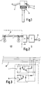
- fig. 1 shows a measurement processor,
- fig. 2 shows schematically a circuit connection containing several, possibly a few hundred measurement processors, and
- fig. 3 shows optoisolators in one single measurement processor.
- In fig. 1 there is shown a complete measurement processor s. This processor is designed as a unit, which in its lower, elongated end part accomodates a number of sensors for measuring different physical parameters for an accumulator cell. In the top housing a microprocessor is located, which microprocessor reads measurement values from the respective sensors, provides current feed to the same sensors, and also delivers the measurement values, possibly in a somewhat processed form, via the connection cable c to a data bus d (see fig. 2). The microprocessor is also adapted to receive requests via the same data bus.
- Reference numerals a and b indicate respectively positive and negative voltage feed wire connected to the poles of the accumulator cell where measurements shall be conducted by the measurement processor. Besides, also the cell voltage is measured by means of these two wires a, b.
- Other physical parameters to be measured are, typically, electrolyte density, electrolyte level and electrolyte temperature.
- Reference numeral c designates a two-pair cable connected to a common four-conductor data bus d.
- In fig. 2 the data bus d, measurement processors s and connection cables c from the measurement processors to the data bus are also present. These elements are located in the explosion dangerous area designated EX, and the data bus d leads out into a safe area S outside, where a so-called "zener
barrier" e is placed in front of a collecting computer f which receives measurement data from the data bus d. This collecting computer f communicates with a control room via a data line g. - A detail of the measurement processor microprocessor is shown in fig. 3, i.e. the detail consists of two optoisolators h and i, respectively an optoisolator for addressing the measurement processor s from the collecting computer f, and an optoisolator via which the measurement processor s retransmits signals.
- As previously mentioned, the measurement processor s may contain several sensors for measuring cell voltage, temperature, electrolyte level and electrolyte density for example. In addition, the measurement processor contains a microprocessor which collects and scales the measurement values from the different sensors. The microprocessor will also control the voltage feed to the different sensors, so that the voltage is disconnected in those periods where no measurements are conducted. The total power comsumption can then be reduced to a minimum when the sensors are "asleep". Only that part of the microprocessor which reads and recognizes its own address, possibly a common request, needs any power in this period.
- Each measurement processor has its own number, stored in e.g. an EEPROM in the microprocessor, and they can be addressed either one by one, or in larger groups.
- The measurement processor is preferably mounted solidly in the accumulator cell, and the feed voltage for the measurement processor is taken from the accumulator cell poles. This means that preferably the measurement processor can be manufactured as part of the lead accumulator cell, and consequently it must be zone classified as a part thereof.
- Also regarding e.g. military certification procedures it will be favourable to define the measurement processor as part of the accumulator cell, or the measurement processor system as part of the accumulator cell battery.
- Lead accumulators are often built with two cells in a block. It is possible to provide a voltage from a series connection of two cells on the voltage feed wires. This may be favourable in certain cases, when it is desirable that the measurement processor shall function even when the cell voltage is substantially lower than the ordinarily acceptable minimum.
- When each measurement processor has its feed voltage from the cell in which a level is to be measured (or possibly a cell in series with a neigbouring cell), the following is achieved: The sensor which reads electrolyte level can be of a capacitive type, using the electrolyte as one condenser side of the sensor. Thereby is eliminated the possible influence on the measurement from the varying electrical characteristics of the liquid, cp. British patent no. 1.318.512.
- The connection cable c is connected to respectively transmitter and receiver in two different optoisolators included in the microprocessor of the measuring processor. These optoisolators secure the necessary galvanic separation between the data line and the remaining part of the measurement processor. (The measurement processor may be situated at a potential of more than 1000 volts, while the data line has earth potential via the data collecting unit f.)
- The multiplexing of the measurement processors can be implemented in many well known manners, and this constitutes no part of the present invention.
Claims (9)
- A method for simultaneously monitoring the electrolyte liquid level in a number of accumulator cells which are possibly grouped in accumulator blocks containing at least two cells per block, wherea microprocessor incorporated in a special measurement processor arranged in correspondence with each accumulator cell, reads measurement values from a sensor which is also incorporated in the same measurement processor and adapted to measure the electrolyte liquid level in the cell,each measurement processor delivering the acquired measurement information via a connection cable to a common data bus which is connected to a collecting computer,characterized in that the electrolyte liquid level sensor, which is of the capacitive type, utilizes the electrolyte liquid itself as one capacitor side, and that the necessary power feed for the microprocessor and sensor in the measurement processor is taken from the poles of the same accumulator cell or from the poles of the accumulator block comprising said cell, thereby providing a galvanic connection to only one fixed potential for said sensor.
- A method as claimed in claim 1,
characterized i n that the microprocessor in each measurement processor by itself reduces the power consumption of the measurement processor by disconnecting all unnecessary microprocessor parts as well as the sensor in those periods where measurements are not conducted. - A means for simultaneously monitoring the electrolyte liquid level in a number of accumulator cells which are possibly grouped in accumulator blocks containing at least two cells per block,each accumulator cell having a corresponding special measurement processor (s) which comprises a sensor adapted for measuring the electrolyte liquid level in the cell and a and a microprocessor adapted to read and possibly process measurement values from the sensor,each measurement processor (s) being connected via a connection cable (c) to a common data bus (d) which is also connected to a collecting computer (f),characterized in that the electrolyte liquid constitutes one capacitor side of said sensor, which is of the capacitive type, and that each measurement processor (s) is connected to the poles of its corresponding accumulator cell or of the accumulator block comprising said cell, for feeding current to the microprocessor and the sensor of said measurement processor (s).
- A means as claimed in claim 3,
characterized in that each measurement processor (s) constitutes an integral unit adapted to be fixed or screwed in place in an accumulator cell. - A means as claimed in claim 3,
characterized in that each measurement processor (s) is incorporated as an integrated part of an accumulator cell. - A means as claimed in any one of claims 3-5,
characterized in that each measurement processor (s) comprises further sensors for measuring the accumulator liquid temperature and density as well as the pole voltage of the accumulator cell. - A means as claimed in any one of claims 3-6,
characterized in that the microprocessor in each measurement processor (s) is adapted to reduce the power consumption of the measurement processor (s) by disconnecting all unnecessary microprocessor parts as well as the level sensor and possible further sensors in those periods where measurements are not conducted. - The use of a means as claimed in any one of claims 3-7, as a monitoring means for an accumulator battery in a submarine.
- The use of a means as claimed in any one of claims 3-7, as a monitoring means for an emergency power unit which comprises a number of accumulator cells.
Applications Claiming Priority (3)
| Application Number | Priority Date | Filing Date | Title |
|---|---|---|---|
| NO910984A NO174446C (en) | 1991-03-12 | 1991-03-12 | Method and apparatus for monitoring electrolyte level in accumulator cells |
| NO910984 | 1991-03-12 | ||
| PCT/NO1992/000045 WO1992016979A1 (en) | 1991-03-12 | 1992-03-11 | System for collecting measurement data in battery rooms |
Publications (2)
| Publication Number | Publication Date |
|---|---|
| EP0575448A1 EP0575448A1 (en) | 1993-12-29 |
| EP0575448B1 true EP0575448B1 (en) | 1996-06-12 |
Family
ID=19893949
Family Applications (1)
| Application Number | Title | Priority Date | Filing Date |
|---|---|---|---|
| EP92907042A Expired - Lifetime EP0575448B1 (en) | 1991-03-12 | 1992-03-11 | System for collecting measurement data in battery rooms |
Country Status (9)
| Country | Link |
|---|---|
| EP (1) | EP0575448B1 (en) |
| AT (1) | ATE139373T1 (en) |
| AU (1) | AU670745B2 (en) |
| DE (1) | DE69211543T2 (en) |
| DK (1) | DK0575448T3 (en) |
| ES (1) | ES2092102T3 (en) |
| GR (1) | GR3021048T3 (en) |
| NO (1) | NO174446C (en) |
| WO (1) | WO1992016979A1 (en) |
Families Citing this family (6)
| Publication number | Priority date | Publication date | Assignee | Title |
|---|---|---|---|---|
| US5622789A (en) * | 1994-09-12 | 1997-04-22 | Apple Computer, Inc. | Battery cell having an internal circuit for controlling its operation |
| SE516191C2 (en) * | 1996-05-14 | 2001-11-26 | Intra Dev As | Pilot cell for battery |
| DE29611978U1 (en) * | 1996-07-10 | 1997-02-13 | Muntermann Axel | accumulator |
| NO316720B1 (en) * | 2002-06-28 | 2004-04-13 | El Watch As | Temperature monitoring system in electrical equipment |
| DE102008043921A1 (en) * | 2008-11-20 | 2010-05-27 | Robert Bosch Gmbh | Device for electrical cell voltage measurements |
| DE102010003040B9 (en) * | 2010-03-18 | 2015-01-08 | Hoppecke Technologies Gmbh & Co. Kg | Apparatus and method for detecting the electrolyte level of an electrochemical cell of a battery |
Family Cites Families (4)
| Publication number | Priority date | Publication date | Assignee | Title |
|---|---|---|---|---|
| US4329406A (en) * | 1981-03-27 | 1982-05-11 | Dahl Ernest A | Specific gravity transducer and battery performance indicator |
| DE3702591A1 (en) * | 1987-01-29 | 1988-08-11 | Sonnenschein Accumulatoren | CIRCUIT TO CONTINUOUSLY CHECK THE QUALITY OF A MULTI-CELL BATTERY |
| DE4014737A1 (en) * | 1989-05-12 | 1990-11-15 | Fraunhofer Ges Forschung | Physical value determn. for accumulator - measures process input values of energy storage which are processed in computer |
| US5132626A (en) * | 1989-05-31 | 1992-07-21 | Amoco Corporation | Electrolytic storage cell monitoring system |
-
1991
- 1991-03-12 NO NO910984A patent/NO174446C/en not_active IP Right Cessation
-
1992
- 1992-03-11 DE DE69211543T patent/DE69211543T2/en not_active Expired - Fee Related
- 1992-03-11 AU AU14337/92A patent/AU670745B2/en not_active Ceased
- 1992-03-11 DK DK92907042.3T patent/DK0575448T3/en active
- 1992-03-11 ES ES92907042T patent/ES2092102T3/en not_active Expired - Lifetime
- 1992-03-11 AT AT92907042T patent/ATE139373T1/en not_active IP Right Cessation
- 1992-03-11 WO PCT/NO1992/000045 patent/WO1992016979A1/en active IP Right Grant
- 1992-03-11 EP EP92907042A patent/EP0575448B1/en not_active Expired - Lifetime
-
1996
- 1996-09-13 GR GR960402416T patent/GR3021048T3/en unknown
Also Published As
| Publication number | Publication date |
|---|---|
| EP0575448A1 (en) | 1993-12-29 |
| ES2092102T3 (en) | 1996-11-16 |
| NO910984L (en) | 1992-09-14 |
| DK0575448T3 (en) | 1996-12-30 |
| NO910984D0 (en) | 1991-03-12 |
| AU670745B2 (en) | 1996-08-01 |
| DE69211543T2 (en) | 1997-02-06 |
| NO174446B (en) | 1994-01-24 |
| NO174446C (en) | 1994-05-04 |
| DE69211543D1 (en) | 1996-07-18 |
| WO1992016979A1 (en) | 1992-10-01 |
| GR3021048T3 (en) | 1996-12-31 |
| AU1433792A (en) | 1992-10-21 |
| ATE139373T1 (en) | 1996-06-15 |
Similar Documents
| Publication | Publication Date | Title |
|---|---|---|
| EP0074444B1 (en) | Rechargeable electric battery system | |
| US10116149B1 (en) | Automatic control system for a rechargeable battery system | |
| CN102545307A (en) | Accumulator control device and method and system for electric auxiliary supply | |
| CN104054213B (en) | For the cell apparatus of motor vehicle | |
| CN101399456A (en) | Multi-series battery control system | |
| NO161198B (en) | CLUTCH DEVICE FOR CAPACITY DEPENDENT CHARGING OF AN ACCUMULATOR. | |
| CN210881686U (en) | Battery management device with voice broadcast function and electric automobile | |
| EP0575448B1 (en) | System for collecting measurement data in battery rooms | |
| CN108362332A (en) | A kind of electrical control cabinet tele-control system based on Internet of Things | |
| CN206849218U (en) | Fire detector, rack and fire detecting system | |
| CN108248445A (en) | Master-slave integrated cell managing device and electric vehicle | |
| JP2005110439A (en) | Electric double layer capacitor device | |
| KR20000029794A (en) | Process and device for monitoring and/or controlling charging of a modular battery, particularly in a battery powered vehicle | |
| CN210657142U (en) | Transformer substation grounding device cathodic protection potential detection system | |
| CN110161415A (en) | A kind of battery current acquisition system and diagnostic method | |
| CN212486185U (en) | Sensing monitoring devices soaks based on LORA technique | |
| CN108258343A (en) | From control module and battery management system | |
| CN213458398U (en) | Alarm device and power equipment maintenance system | |
| CN108258344A (en) | From control module and battery management system | |
| CN208272059U (en) | From control module and battery management system | |
| CN110656335A (en) | Transformer substation grounding device cathode protection potential detection system and detection method thereof | |
| JP5371651B2 (en) | Vehicle power supply system and communication device | |
| CN110474404A (en) | A kind of charging equipment for power tools and electric tool charging system | |
| CN212875422U (en) | Battery management system and device | |
| CN215496831U (en) | Power battery and vehicle |
Legal Events
| Date | Code | Title | Description |
|---|---|---|---|
| PUAI | Public reference made under article 153(3) epc to a published international application that has entered the european phase |
Free format text: ORIGINAL CODE: 0009012 |
|
| 17P | Request for examination filed |
Effective date: 19931012 |
|
| AK | Designated contracting states |
Kind code of ref document: A1 Designated state(s): AT BE CH DE DK ES FR GB GR IT LI LU MC NL |
|
| RAP1 | Party data changed (applicant data changed or rights of an application transferred) |
Owner name: VARTA BATTERI AB |
|
| 17Q | First examination report despatched |
Effective date: 19950814 |
|
| GRAH | Despatch of communication of intention to grant a patent |
Free format text: ORIGINAL CODE: EPIDOS IGRA |
|
| GRAH | Despatch of communication of intention to grant a patent |
Free format text: ORIGINAL CODE: EPIDOS IGRA |
|
| GRAA | (expected) grant |
Free format text: ORIGINAL CODE: 0009210 |
|
| AK | Designated contracting states |
Kind code of ref document: B1 Designated state(s): AT BE CH DE DK ES FR GB GR IT LI LU MC NL SE |
|
| PG25 | Lapsed in a contracting state [announced via postgrant information from national office to epo] |
Ref country code: LI Effective date: 19960612 Ref country code: CH Effective date: 19960612 Ref country code: BE Effective date: 19960612 Ref country code: AT Effective date: 19960612 |
|
| REF | Corresponds to: |
Ref document number: 139373 Country of ref document: AT Date of ref document: 19960615 Kind code of ref document: T |
|
| REF | Corresponds to: |
Ref document number: 69211543 Country of ref document: DE Date of ref document: 19960718 |
|
| ITF | It: translation for a ep patent filed |
Owner name: PROROGA CONCESSA IN DATA: 04.11.96;JACOBACCI & PER |
|
| ET | Fr: translation filed | ||
| REG | Reference to a national code |
Ref country code: ES Ref legal event code: FG2A Ref document number: 2092102 Country of ref document: ES Kind code of ref document: T3 |
|
| REG | Reference to a national code |
Ref country code: GR Ref legal event code: FG4A Free format text: 3021048 |
|
| REG | Reference to a national code |
Ref country code: CH Ref legal event code: PL |
|
| REG | Reference to a national code |
Ref country code: DK Ref legal event code: T3 |
|
| NLS | Nl: assignments of ep-patents |
Owner name: PACIFIC MARINE BATTERIES PTY LTD ACN 008 195131 |
|
| REG | Reference to a national code |
Ref country code: GB Ref legal event code: 732E |
|
| PG25 | Lapsed in a contracting state [announced via postgrant information from national office to epo] |
Ref country code: LU Free format text: LAPSE BECAUSE OF NON-PAYMENT OF DUE FEES Effective date: 19970331 |
|
| PLBE | No opposition filed within time limit |
Free format text: ORIGINAL CODE: 0009261 |
|
| STAA | Information on the status of an ep patent application or granted ep patent |
Free format text: STATUS: NO OPPOSITION FILED WITHIN TIME LIMIT |
|
| REG | Reference to a national code |
Ref country code: ES Ref legal event code: PC2A |
|
| 26N | No opposition filed | ||
| PG25 | Lapsed in a contracting state [announced via postgrant information from national office to epo] |
Ref country code: MC Effective date: 19970930 |
|
| REG | Reference to a national code |
Ref country code: FR Ref legal event code: TP |
|
| PGFP | Annual fee paid to national office [announced via postgrant information from national office to epo] |
Ref country code: FR Payment date: 20010221 Year of fee payment: 10 |
|
| PGFP | Annual fee paid to national office [announced via postgrant information from national office to epo] |
Ref country code: DK Payment date: 20010305 Year of fee payment: 10 |
|
| PGFP | Annual fee paid to national office [announced via postgrant information from national office to epo] |
Ref country code: SE Payment date: 20010307 Year of fee payment: 10 Ref country code: GB Payment date: 20010307 Year of fee payment: 10 |
|
| PGFP | Annual fee paid to national office [announced via postgrant information from national office to epo] |
Ref country code: ES Payment date: 20010309 Year of fee payment: 10 |
|
| PGFP | Annual fee paid to national office [announced via postgrant information from national office to epo] |
Ref country code: GR Payment date: 20010322 Year of fee payment: 10 |
|
| PGFP | Annual fee paid to national office [announced via postgrant information from national office to epo] |
Ref country code: NL Payment date: 20010331 Year of fee payment: 10 |
|
| PGFP | Annual fee paid to national office [announced via postgrant information from national office to epo] |
Ref country code: DE Payment date: 20010426 Year of fee payment: 10 |
|
| REG | Reference to a national code |
Ref country code: GB Ref legal event code: IF02 |
|
| PG25 | Lapsed in a contracting state [announced via postgrant information from national office to epo] |
Ref country code: GB Free format text: LAPSE BECAUSE OF NON-PAYMENT OF DUE FEES Effective date: 20020311 |
|
| PG25 | Lapsed in a contracting state [announced via postgrant information from national office to epo] |
Ref country code: SE Free format text: LAPSE BECAUSE OF NON-PAYMENT OF DUE FEES Effective date: 20020312 Ref country code: ES Free format text: LAPSE BECAUSE OF NON-PAYMENT OF DUE FEES Effective date: 20020312 |
|
| PG25 | Lapsed in a contracting state [announced via postgrant information from national office to epo] |
Ref country code: DK Free format text: LAPSE BECAUSE OF NON-PAYMENT OF DUE FEES Effective date: 20020402 |
|
| PG25 | Lapsed in a contracting state [announced via postgrant information from national office to epo] |
Ref country code: NL Free format text: LAPSE BECAUSE OF NON-PAYMENT OF DUE FEES Effective date: 20021001 Ref country code: DE Free format text: LAPSE BECAUSE OF NON-PAYMENT OF DUE FEES Effective date: 20021001 |
|
| PG25 | Lapsed in a contracting state [announced via postgrant information from national office to epo] |
Ref country code: GR Free format text: LAPSE BECAUSE OF NON-PAYMENT OF DUE FEES Effective date: 20021007 |
|
| EUG | Se: european patent has lapsed |
Ref document number: 92907042.3 |
|
| GBPC | Gb: european patent ceased through non-payment of renewal fee |
Effective date: 20020311 |
|
| REG | Reference to a national code |
Ref country code: DK Ref legal event code: EBP |
|
| PG25 | Lapsed in a contracting state [announced via postgrant information from national office to epo] |
Ref country code: FR Free format text: LAPSE BECAUSE OF NON-PAYMENT OF DUE FEES Effective date: 20021129 |
|
| NLV4 | Nl: lapsed or anulled due to non-payment of the annual fee |
Effective date: 20021001 |
|
| REG | Reference to a national code |
Ref country code: FR Ref legal event code: ST |
|
| REG | Reference to a national code |
Ref country code: ES Ref legal event code: FD2A Effective date: 20030410 |
|
| PG25 | Lapsed in a contracting state [announced via postgrant information from national office to epo] |
Ref country code: IT Free format text: LAPSE BECAUSE OF NON-PAYMENT OF DUE FEES Effective date: 20050311 |