EP0575448B1 - System zum sammeln von messdaten in batterieräumen - Google Patents
System zum sammeln von messdaten in batterieräumen Download PDFInfo
- Publication number
- EP0575448B1 EP0575448B1 EP92907042A EP92907042A EP0575448B1 EP 0575448 B1 EP0575448 B1 EP 0575448B1 EP 92907042 A EP92907042 A EP 92907042A EP 92907042 A EP92907042 A EP 92907042A EP 0575448 B1 EP0575448 B1 EP 0575448B1
- Authority
- EP
- European Patent Office
- Prior art keywords
- accumulator
- measurement processor
- cell
- sensor
- microprocessor
- Prior art date
- Legal status (The legal status is an assumption and is not a legal conclusion. Google has not performed a legal analysis and makes no representation as to the accuracy of the status listed.)
- Expired - Lifetime
Links
Images
Classifications
-
- G—PHYSICS
- G08—SIGNALLING
- G08C—TRANSMISSION SYSTEMS FOR MEASURED VALUES, CONTROL OR SIMILAR SIGNALS
- G08C15/00—Arrangements characterised by the use of multiplexing for the transmission of a plurality of signals over a common path
-
- H—ELECTRICITY
- H01—ELECTRIC ELEMENTS
- H01M—PROCESSES OR MEANS, e.g. BATTERIES, FOR THE DIRECT CONVERSION OF CHEMICAL ENERGY INTO ELECTRICAL ENERGY
- H01M10/00—Secondary cells; Manufacture thereof
- H01M10/42—Methods or arrangements for servicing or maintenance of secondary cells or secondary half-cells
- H01M10/48—Accumulators combined with arrangements for measuring, testing or indicating the condition of cells, e.g. the level or density of the electrolyte
-
- G—PHYSICS
- G01—MEASURING; TESTING
- G01R—MEASURING ELECTRIC VARIABLES; MEASURING MAGNETIC VARIABLES
- G01R31/00—Arrangements for testing electric properties; Arrangements for locating electric faults; Arrangements for electrical testing characterised by what is being tested not provided for elsewhere
- G01R31/36—Arrangements for testing, measuring or monitoring the electrical condition of accumulators or electric batteries, e.g. capacity or state of charge [SoC]
- G01R31/3644—Constructional arrangements
- G01R31/3648—Constructional arrangements comprising digital calculation means, e.g. for performing an algorithm
-
- G—PHYSICS
- G01—MEASURING; TESTING
- G01R—MEASURING ELECTRIC VARIABLES; MEASURING MAGNETIC VARIABLES
- G01R31/00—Arrangements for testing electric properties; Arrangements for locating electric faults; Arrangements for electrical testing characterised by what is being tested not provided for elsewhere
- G01R31/36—Arrangements for testing, measuring or monitoring the electrical condition of accumulators or electric batteries, e.g. capacity or state of charge [SoC]
- G01R31/396—Acquisition or processing of data for testing or for monitoring individual cells or groups of cells within a battery
-
- G—PHYSICS
- G01—MEASURING; TESTING
- G01R—MEASURING ELECTRIC VARIABLES; MEASURING MAGNETIC VARIABLES
- G01R31/00—Arrangements for testing electric properties; Arrangements for locating electric faults; Arrangements for electrical testing characterised by what is being tested not provided for elsewhere
- G01R31/36—Arrangements for testing, measuring or monitoring the electrical condition of accumulators or electric batteries, e.g. capacity or state of charge [SoC]
- G01R31/382—Arrangements for monitoring battery or accumulator variables, e.g. SoC
- G01R31/3835—Arrangements for monitoring battery or accumulator variables, e.g. SoC involving only voltage measurements
-
- Y—GENERAL TAGGING OF NEW TECHNOLOGICAL DEVELOPMENTS; GENERAL TAGGING OF CROSS-SECTIONAL TECHNOLOGIES SPANNING OVER SEVERAL SECTIONS OF THE IPC; TECHNICAL SUBJECTS COVERED BY FORMER USPC CROSS-REFERENCE ART COLLECTIONS [XRACs] AND DIGESTS
- Y02—TECHNOLOGIES OR APPLICATIONS FOR MITIGATION OR ADAPTATION AGAINST CLIMATE CHANGE
- Y02E—REDUCTION OF GREENHOUSE GAS [GHG] EMISSIONS, RELATED TO ENERGY GENERATION, TRANSMISSION OR DISTRIBUTION
- Y02E60/00—Enabling technologies; Technologies with a potential or indirect contribution to GHG emissions mitigation
- Y02E60/10—Energy storage using batteries
Definitions
- the present invention relates to a method and a means for collecting measurement values from a number of sensors monitoring physical parameters in respective ones of a series of accumulator cells. This may for example concern lead accumulators in a submarine, or emergency power batteries in power stations, hospitals or similar.
- the accumulator cells are located as a collection in a battery of cells in a room which is classified as explosion dangerous. It is a known fact that lead accumulators liberate oxyhydrogen gas during charging.
- the idea of the present invention is to solve in a practical manner the problems arising in connection with both complex cable multitudes and the use of sufficiently low current to achieve a certificate in explosion dangerous areas class 1 or 0, and at the same time the problem in connection with high DC voltage potentials is solved.
- a means in accordance with the present invention also complies with all necessary requirements for approval in the explosion dangerous surroundings mentioned above.
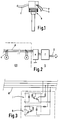
- a complete measurement processor s This processor is designed as a unit, which in its lower, elongated end part accomodates a number of sensors for measuring different physical parameters for an accumulator cell.
- a microprocessor In the top housing a microprocessor is located, which microprocessor reads measurement values from the respective sensors, provides current feed to the same sensors, and also delivers the measurement values, possibly in a somewhat processed form, via the connection cable c to a data bus d (see fig. 2).
- the microprocessor is also adapted to receive requests via the same data bus.
- Reference numerals a and b indicate respectively positive and negative voltage feed wire connected to the poles of the accumulator cell where measurements shall be conducted by the measurement processor. Besides, also the cell voltage is measured by means of these two wires a, b.
- electrolyte density e.g., electrolyte density, electrolyte level and electrolyte temperature.
- Reference numeral c designates a two-pair cable connected to a common four-conductor data bus d.
- the data bus d, measurement processors s and connection cables c from the measurement processors to the data bus are also present. These elements are located in the explosion dangerous area designated EX, and the data bus d leads out into a safe area S outside, where a so-called "zener barrier" e is placed in front of a collecting computer f which receives measurement data from the data bus d. This collecting computer f communicates with a control room via a data line g.
- a detail of the measurement processor microprocessor is shown in fig. 3, i.e. the detail consists of two optoisolators h and i, respectively an optoisolator for addressing the measurement processor s from the collecting computer f, and an optoisolator via which the measurement processor s retransmits signals.
- the measurement processor s may contain several sensors for measuring cell voltage, temperature, electrolyte level and electrolyte density for example.
- the measurement processor contains a microprocessor which collects and scales the measurement values from the different sensors. The microprocessor will also control the voltage feed to the different sensors, so that the voltage is disconnected in those periods where no measurements are conducted. The total power comsumption can then be reduced to a minimum when the sensors are "asleep". Only that part of the microprocessor which reads and recognizes its own address, possibly a common request, needs any power in this period.
- Each measurement processor has its own number, stored in e.g. an EEPROM in the microprocessor, and they can be addressed either one by one, or in larger groups.
- the measurement processor is preferably mounted solidly in the accumulator cell, and the feed voltage for the measurement processor is taken from the accumulator cell poles. This means that preferably the measurement processor can be manufactured as part of the lead accumulator cell, and consequently it must be zone classified as a part thereof.
- the measurement processor as part of the accumulator cell, or the measurement processor system as part of the accumulator cell battery.
- Lead accumulators are often built with two cells in a block. It is possible to provide a voltage from a series connection of two cells on the voltage feed wires. This may be favourable in certain cases, when it is desirable that the measurement processor shall function even when the cell voltage is substantially lower than the ordinarily acceptable minimum.
- the sensor which reads electrolyte level can be of a capacitive type, using the electrolyte as one condenser side of the sensor. Thereby is eliminated the possible influence on the measurement from the varying electrical characteristics of the liquid, cp. British patent no. 1.318.512.
- connection cable c is connected to respectively transmitter and receiver in two different optoisolators included in the microprocessor of the measuring processor. These optoisolators secure the necessary galvanic separation between the data line and the remaining part of the measurement processor.
- the measurement processor may be situated at a potential of more than 1000 volts, while the data line has earth potential via the data collecting unit f.
- the multiplexing of the measurement processors can be implemented in many well known manners, and this constitutes no part of the present invention.
Landscapes
- Physics & Mathematics (AREA)
- General Physics & Mathematics (AREA)
- Chemical Kinetics & Catalysis (AREA)
- Engineering & Computer Science (AREA)
- Electrochemistry (AREA)
- General Chemical & Material Sciences (AREA)
- Chemical & Material Sciences (AREA)
- Manufacturing & Machinery (AREA)
- Secondary Cells (AREA)
- Arrangements For Transmission Of Measured Signals (AREA)
- Measurement Of The Respiration, Hearing Ability, Form, And Blood Characteristics Of Living Organisms (AREA)
- Testing Or Calibration Of Command Recording Devices (AREA)
- Fuel Cell (AREA)
- Electric Double-Layer Capacitors Or The Like (AREA)
Claims (9)
- Verfahren zum gleichzeitigen Aufzeichnen des Elektrolyt-Flüssigkeitsstandes in einer Anzahl von Akkumulatorzellen, welche in Akkumulatorblöcken gruppiert sein können, die wenigstens zwei Zellen pro Block enthalten, wobeiein Mikroprozessor, welcher in einem speziellen Meßprozessor untergebracht ist, der zugehörig zu jeder Akkumulatorzelle angeordnet ist, die Meßdaten von einem Sensor liest, welcher auch in dem gleichen Meßprozessor untergebracht ist und geeignet ist, den Elektrolyt-Flüssigkeitsstand in der Zelle zu messen, und wobeijeder Meßprozessor die gewonnene Meßinformation über ein Verbindungskabel an einen gemeinsamen Datenbus übermittelt, welcher mit einem auswertenden Computer verbunden ist,dadurch gekennzeichnet, daß der Elektrolyt-Flüssigkeitsstandsensor, welcher vom kapazitiven Typ ist, die Elektrolyt-Flüssigkeit selbst als eine Kondensatorplatte einsetzt und daß die notwendige Energie für den Mikroprozessor und den Sensor in dem Meßprozessor von den Polen der gleichen Akkumulatorzelle oder von den Polen des Akkumulatorblocks, welcher die Zellen umfasst abgenommen wird, wodurch eine galvanische Verbindung zu nur einem festen Potential für den Sensor bereitgestellt wird.
- Verfahren nach Anspruch 1, dadurch gekennzeichnet, daß der Mikroprozessor in jedem Meßprozessor selbst den Energieverbrauch des Meßprozessors reduziert, indem alle unbenötigten Mikroprozessorbereiche wie auch der Sensor in den Zeiträumen, in welchen die Messungen nicht durchgeführt werden, abgeschaltet werden.
- Einrichtung um gleichzeitig den Elektrolyt-Flüssigkeitsstand in einer Anzahl von Akkumulatorzellen aufzuzeichnen, welche in Akkumulatorblöcken, welche wenigstens zwei Zellen pro Block enthalten, angeordnet sein können, wobeijede Akkumulatorzelle einen zugehörigen speziellen Meßprozessor (s) aufweist, umfassend einen Sensor, der zum Messen des Elektrolyte-Flüssigkeitsstandes in der Zelle geeignet ist, und einen Mikroprozessor, welcher geeignet ist, die Meßdaten des Sensors zu lesen und möglicherweise zu verarbeiten,jeder Meßprozessor (s) über ein Verbindungskabel (c) mit einem gemeinsamen Datenbus (d) verbunden ist, welcher auch mit einem auswertenden Computer (f) verbunden ist,dadurch gekennzeichnet, daß die Elektrolyt-Flüssigkeit eine Kondensatorplatte des Sensors bildet, welcher vom kapazitiven Typ ist und daß jeder Meßprozessor mit den Polen der entsprechenden Akkumulatorzelle oder des Akkumulatorblocks, welcher die Zelle umfasst, verbunden ist, um dem Mikroprozessor und dem Sensor des Meßprozessors (s) Strom zuzuführen.
- Vorrichtung nach Anspruch 3, dadurch gekennzeichnet, daß jeder Meßprozessor (s) eine integrale Einheit bildet, welche geeignet ist, an einer Stelle in einer Akkumulatorzelle befestigt oder angeschraubt zu werden.
- Vorrichtung nach Anspruch 3, dadurch gekennzeichnet, daß jeder Meßprozessor (s) als ein integrierter Teil einer Akkumulatorzelle eingefügt wird.
- Vorrichtung nach einem der Ansprüche 3-5, dadurch gekennzeichnet, daß jeder Meßprozessor (s) des weiteren Sensoren zum Messen der Temperatur und der Dichte der Akkumulatorflüssigkeit, wie auch der Polspannung der Akkumulatorzelle umfaßt.
- Vorrichtung nach einem der Ansprüche 3-6, dadurch gekennzeichnet, daß der Mikroprozessor geeignet ist, den Stromverbrauch des Meßprozessors (s) zu reduzieren, indem alle unbenötigen Mikroprozessorbereiche wie auch der Flüssigkeitsstandsensor und möglicherweise weitere Sensoren in den Zeiträumen, in denen die Messungen nicht durchgeführt werden, abgeschaltet sind.
- Verwendung einer Einrichtung nach einem der Ansprüche 3-7 als eine Aufzeichnungseinrichtung für einen Akkumulator für ein U-Boot.
- Verwendung einer Einrichtung nach einem der Ansprüche 3-7 als eine Aufzeichnungseinrichtung für eine Notstromeinheit, welche eine Anzahl von Akkumulatorzelle umfaßt.
Applications Claiming Priority (3)
| Application Number | Priority Date | Filing Date | Title |
|---|---|---|---|
| NO910984 | 1991-03-12 | ||
| NO910984A NO174446C (no) | 1991-03-12 | 1991-03-12 | Fremgangsmåte og anordning for overvåkning av elektrolytt-nivå i akkumulatorceller |
| PCT/NO1992/000045 WO1992016979A1 (en) | 1991-03-12 | 1992-03-11 | System for collecting measurement data in battery rooms |
Publications (2)
| Publication Number | Publication Date |
|---|---|
| EP0575448A1 EP0575448A1 (de) | 1993-12-29 |
| EP0575448B1 true EP0575448B1 (de) | 1996-06-12 |
Family
ID=19893949
Family Applications (1)
| Application Number | Title | Priority Date | Filing Date |
|---|---|---|---|
| EP92907042A Expired - Lifetime EP0575448B1 (de) | 1991-03-12 | 1992-03-11 | System zum sammeln von messdaten in batterieräumen |
Country Status (9)
| Country | Link |
|---|---|
| EP (1) | EP0575448B1 (de) |
| AT (1) | ATE139373T1 (de) |
| AU (1) | AU670745B2 (de) |
| DE (1) | DE69211543T2 (de) |
| DK (1) | DK0575448T3 (de) |
| ES (1) | ES2092102T3 (de) |
| GR (1) | GR3021048T3 (de) |
| NO (1) | NO174446C (de) |
| WO (1) | WO1992016979A1 (de) |
Families Citing this family (6)
| Publication number | Priority date | Publication date | Assignee | Title |
|---|---|---|---|---|
| US5622789A (en) * | 1994-09-12 | 1997-04-22 | Apple Computer, Inc. | Battery cell having an internal circuit for controlling its operation |
| SE516191C2 (sv) * | 1996-05-14 | 2001-11-26 | Intra Dev As | Pilotcell för batteri |
| DE29611978U1 (de) * | 1996-07-10 | 1997-02-13 | Muntermann, Axel, 35583 Wetzlar | Akkumulator |
| NO316720B1 (no) * | 2002-06-28 | 2004-04-13 | El Watch As | System for overvåkning av temperatur i elektrisk utstyr |
| DE102008043921A1 (de) * | 2008-11-20 | 2010-05-27 | Robert Bosch Gmbh | Vorrichtung für elektrische Zellenspannungsmessungen |
| DE102010003040B9 (de) * | 2010-03-18 | 2015-01-08 | Hoppecke Technologies Gmbh & Co. Kg | Vorrichtung und Verfahren zur Feststellung des Elektrolytfüllstandes einer elektrochemischen Zelle einer Batterie |
Family Cites Families (4)
| Publication number | Priority date | Publication date | Assignee | Title |
|---|---|---|---|---|
| US4329406A (en) * | 1981-03-27 | 1982-05-11 | Dahl Ernest A | Specific gravity transducer and battery performance indicator |
| DE3702591A1 (de) * | 1987-01-29 | 1988-08-11 | Sonnenschein Accumulatoren | Schaltung zur laufenden ueberpruefung der qualitaet einer mehrzelligen batterie |
| DE4014737A1 (de) * | 1989-05-12 | 1990-11-15 | Fraunhofer Ges Forschung | Verfahren zur bestimmung von physikalischen groessen von wiederaufladbaren elektrischen energiespeichern und vorrichtung zur durchfuehrung des verfahrens |
| US5132626A (en) * | 1989-05-31 | 1992-07-21 | Amoco Corporation | Electrolytic storage cell monitoring system |
-
1991
- 1991-03-12 NO NO910984A patent/NO174446C/no not_active IP Right Cessation
-
1992
- 1992-03-11 AT AT92907042T patent/ATE139373T1/de not_active IP Right Cessation
- 1992-03-11 DE DE69211543T patent/DE69211543T2/de not_active Expired - Fee Related
- 1992-03-11 DK DK92907042.3T patent/DK0575448T3/da active
- 1992-03-11 ES ES92907042T patent/ES2092102T3/es not_active Expired - Lifetime
- 1992-03-11 WO PCT/NO1992/000045 patent/WO1992016979A1/en not_active Ceased
- 1992-03-11 EP EP92907042A patent/EP0575448B1/de not_active Expired - Lifetime
- 1992-03-11 AU AU14337/92A patent/AU670745B2/en not_active Ceased
-
1996
- 1996-09-13 GR GR960402416T patent/GR3021048T3/el unknown
Also Published As
| Publication number | Publication date |
|---|---|
| NO174446B (no) | 1994-01-24 |
| DE69211543D1 (de) | 1996-07-18 |
| AU670745B2 (en) | 1996-08-01 |
| GR3021048T3 (en) | 1996-12-31 |
| ES2092102T3 (es) | 1996-11-16 |
| WO1992016979A1 (en) | 1992-10-01 |
| ATE139373T1 (de) | 1996-06-15 |
| DK0575448T3 (da) | 1996-12-30 |
| AU1433792A (en) | 1992-10-21 |
| EP0575448A1 (de) | 1993-12-29 |
| NO174446C (no) | 1994-05-04 |
| NO910984L (no) | 1992-09-14 |
| NO910984D0 (no) | 1991-03-12 |
| DE69211543T2 (de) | 1997-02-06 |
Similar Documents
| Publication | Publication Date | Title |
|---|---|---|
| US5321626A (en) | Battery performance monitoring and forecasting system | |
| EP0074444B1 (de) | System für wiederaufladbare Batterien | |
| US10367239B1 (en) | Integral battery temperature control system | |
| US11555862B2 (en) | Ground fault detection method and system | |
| NO161198B (no) | Koplingsanordning for kapasitetsavhengig etterladning av en akkumulator. | |
| EP0575448B1 (de) | System zum sammeln von messdaten in batterieräumen | |
| CN108248445A (zh) | 主从一体式电池管理装置及电动汽车 | |
| JP2005110439A (ja) | 電気二重層コンデンサ装置 | |
| KR20000029794A (ko) | 배터리구동차량에서의모듈로이루어진배터리의감시및/또는충전제어방법및그장치 | |
| CN209046357U (zh) | 一种带接口监控装置的ups设备 | |
| CN110656335A (zh) | 一种变电站接地装置阴极保护电位探测系统及其探测方法 | |
| CN207758592U (zh) | 一种电动汽车安全充电系统及设备 | |
| CN212486185U (zh) | 一种基于lora技术的浸水传感监测装置 | |
| JP7056771B1 (ja) | 電源装置 | |
| CN210154700U (zh) | 一种具有烟雾及温度检测电路功能的充电桩电路板 | |
| JP5371651B2 (ja) | 車両用電源システムおよび通信装置 | |
| CN215496831U (zh) | 一种动力电池及车辆 | |
| JPH11136867A (ja) | 蓄電システム | |
| RU235664U1 (ru) | Устройство анализа состояния аккумуляторных батарей | |
| US20260016544A1 (en) | Method and apparatus for mapping energy storage module location in a modular battery energy storage system | |
| CN221926590U (zh) | 成端监测装置 | |
| CN223297665U (zh) | 一种接地棒数据采集电路 | |
| CN209496972U (zh) | 一种电池管理系统输入输出信号检测装置 | |
| CN109507607A (zh) | 便携式蓄电池组电压采集仪 | |
| CN117930074A (zh) | 成端监测装置 |
Legal Events
| Date | Code | Title | Description |
|---|---|---|---|
| PUAI | Public reference made under article 153(3) epc to a published international application that has entered the european phase |
Free format text: ORIGINAL CODE: 0009012 |
|
| 17P | Request for examination filed |
Effective date: 19931012 |
|
| AK | Designated contracting states |
Kind code of ref document: A1 Designated state(s): AT BE CH DE DK ES FR GB GR IT LI LU MC NL |
|
| RAP1 | Party data changed (applicant data changed or rights of an application transferred) |
Owner name: VARTA BATTERI AB |
|
| 17Q | First examination report despatched |
Effective date: 19950814 |
|
| GRAH | Despatch of communication of intention to grant a patent |
Free format text: ORIGINAL CODE: EPIDOS IGRA |
|
| GRAH | Despatch of communication of intention to grant a patent |
Free format text: ORIGINAL CODE: EPIDOS IGRA |
|
| GRAA | (expected) grant |
Free format text: ORIGINAL CODE: 0009210 |
|
| AK | Designated contracting states |
Kind code of ref document: B1 Designated state(s): AT BE CH DE DK ES FR GB GR IT LI LU MC NL SE |
|
| PG25 | Lapsed in a contracting state [announced via postgrant information from national office to epo] |
Ref country code: LI Effective date: 19960612 Ref country code: CH Effective date: 19960612 Ref country code: BE Effective date: 19960612 Ref country code: AT Effective date: 19960612 |
|
| REF | Corresponds to: |
Ref document number: 139373 Country of ref document: AT Date of ref document: 19960615 Kind code of ref document: T |
|
| REF | Corresponds to: |
Ref document number: 69211543 Country of ref document: DE Date of ref document: 19960718 |
|
| ITF | It: translation for a ep patent filed | ||
| ET | Fr: translation filed | ||
| REG | Reference to a national code |
Ref country code: ES Ref legal event code: FG2A Ref document number: 2092102 Country of ref document: ES Kind code of ref document: T3 |
|
| REG | Reference to a national code |
Ref country code: GR Ref legal event code: FG4A Free format text: 3021048 |
|
| REG | Reference to a national code |
Ref country code: CH Ref legal event code: PL |
|
| REG | Reference to a national code |
Ref country code: DK Ref legal event code: T3 |
|
| NLS | Nl: assignments of ep-patents |
Owner name: PACIFIC MARINE BATTERIES PTY LTD ACN 008 195131 |
|
| REG | Reference to a national code |
Ref country code: GB Ref legal event code: 732E |
|
| PG25 | Lapsed in a contracting state [announced via postgrant information from national office to epo] |
Ref country code: LU Free format text: LAPSE BECAUSE OF NON-PAYMENT OF DUE FEES Effective date: 19970331 |
|
| PLBE | No opposition filed within time limit |
Free format text: ORIGINAL CODE: 0009261 |
|
| REG | Reference to a national code |
Ref country code: ES Ref legal event code: PC2A |
|
| 26N | No opposition filed | ||
| PG25 | Lapsed in a contracting state [announced via postgrant information from national office to epo] |
Ref country code: MC Effective date: 19970930 |
|
| REG | Reference to a national code |
Ref country code: FR Ref legal event code: TP |
|
| PGFP | Annual fee paid to national office [announced via postgrant information from national office to epo] |
Ref country code: FR Payment date: 20010221 Year of fee payment: 10 |
|
| PGFP | Annual fee paid to national office [announced via postgrant information from national office to epo] |
Ref country code: DK Payment date: 20010305 Year of fee payment: 10 |
|
| PGFP | Annual fee paid to national office [announced via postgrant information from national office to epo] |
Ref country code: SE Payment date: 20010307 Year of fee payment: 10 Ref country code: GB Payment date: 20010307 Year of fee payment: 10 |
|
| PGFP | Annual fee paid to national office [announced via postgrant information from national office to epo] |
Ref country code: ES Payment date: 20010309 Year of fee payment: 10 |
|
| PGFP | Annual fee paid to national office [announced via postgrant information from national office to epo] |
Ref country code: GR Payment date: 20010322 Year of fee payment: 10 |
|
| PGFP | Annual fee paid to national office [announced via postgrant information from national office to epo] |
Ref country code: NL Payment date: 20010331 Year of fee payment: 10 |
|
| PGFP | Annual fee paid to national office [announced via postgrant information from national office to epo] |
Ref country code: DE Payment date: 20010426 Year of fee payment: 10 |
|
| REG | Reference to a national code |
Ref country code: GB Ref legal event code: IF02 |
|
| PG25 | Lapsed in a contracting state [announced via postgrant information from national office to epo] |
Ref country code: GB Free format text: LAPSE BECAUSE OF NON-PAYMENT OF DUE FEES Effective date: 20020311 |
|
| PG25 | Lapsed in a contracting state [announced via postgrant information from national office to epo] |
Ref country code: SE Free format text: LAPSE BECAUSE OF NON-PAYMENT OF DUE FEES Effective date: 20020312 Ref country code: ES Free format text: LAPSE BECAUSE OF NON-PAYMENT OF DUE FEES Effective date: 20020312 |
|
| PG25 | Lapsed in a contracting state [announced via postgrant information from national office to epo] |
Ref country code: DK Free format text: LAPSE BECAUSE OF NON-PAYMENT OF DUE FEES Effective date: 20020402 |
|
| PG25 | Lapsed in a contracting state [announced via postgrant information from national office to epo] |
Ref country code: NL Free format text: LAPSE BECAUSE OF NON-PAYMENT OF DUE FEES Effective date: 20021001 Ref country code: DE Free format text: LAPSE BECAUSE OF NON-PAYMENT OF DUE FEES Effective date: 20021001 |
|
| PG25 | Lapsed in a contracting state [announced via postgrant information from national office to epo] |
Ref country code: GR Free format text: LAPSE BECAUSE OF NON-PAYMENT OF DUE FEES Effective date: 20021007 |
|
| EUG | Se: european patent has lapsed |
Ref document number: 92907042.3 |
|
| GBPC | Gb: european patent ceased through non-payment of renewal fee |
Effective date: 20020311 |
|
| REG | Reference to a national code |
Ref country code: DK Ref legal event code: EBP |
|
| PG25 | Lapsed in a contracting state [announced via postgrant information from national office to epo] |
Ref country code: FR Free format text: LAPSE BECAUSE OF NON-PAYMENT OF DUE FEES Effective date: 20021129 |
|
| NLV4 | Nl: lapsed or anulled due to non-payment of the annual fee |
Effective date: 20021001 |
|
| REG | Reference to a national code |
Ref country code: FR Ref legal event code: ST |
|
| REG | Reference to a national code |
Ref country code: ES Ref legal event code: FD2A Effective date: 20030410 |
|
| PG25 | Lapsed in a contracting state [announced via postgrant information from national office to epo] |
Ref country code: IT Free format text: LAPSE BECAUSE OF NON-PAYMENT OF DUE FEES Effective date: 20050311 |