EP0575240B1 - Entfernungsmessgerät für ein Fahrzeug, insbesondere für einen geländegängigen Roboter und mit solch einem Gerät ausgerüstetes Fahrzeug - Google Patents
Entfernungsmessgerät für ein Fahrzeug, insbesondere für einen geländegängigen Roboter und mit solch einem Gerät ausgerüstetes Fahrzeug Download PDFInfo
- Publication number
- EP0575240B1 EP0575240B1 EP93401528A EP93401528A EP0575240B1 EP 0575240 B1 EP0575240 B1 EP 0575240B1 EP 93401528 A EP93401528 A EP 93401528A EP 93401528 A EP93401528 A EP 93401528A EP 0575240 B1 EP0575240 B1 EP 0575240B1
- Authority
- EP
- European Patent Office
- Prior art keywords
- vehicle
- displacement
- odometer
- terrain
- inclination
- Prior art date
- Legal status (The legal status is an assumption and is not a legal conclusion. Google has not performed a legal analysis and makes no representation as to the accuracy of the status listed.)
- Expired - Lifetime
Links
- 238000006073 displacement reaction Methods 0.000 claims description 68
- 238000005259 measurement Methods 0.000 claims description 54
- 230000010354 integration Effects 0.000 claims description 10
- 230000001133 acceleration Effects 0.000 claims description 2
- 238000001914 filtration Methods 0.000 claims description 2
- 238000004364 calculation method Methods 0.000 description 16
- 230000033001 locomotion Effects 0.000 description 10
- 239000013598 vector Substances 0.000 description 6
- 230000004927 fusion Effects 0.000 description 5
- 230000009183 running Effects 0.000 description 4
- 240000008042 Zea mays Species 0.000 description 3
- 230000000694 effects Effects 0.000 description 3
- 210000000056 organ Anatomy 0.000 description 2
- 238000005096 rolling process Methods 0.000 description 2
- 239000000725 suspension Substances 0.000 description 2
- 241000282412 Homo Species 0.000 description 1
- 241000282414 Homo sapiens Species 0.000 description 1
- 241000135309 Processus Species 0.000 description 1
- 230000008859 change Effects 0.000 description 1
- 238000006243 chemical reaction Methods 0.000 description 1
- 239000003638 chemical reducing agent Substances 0.000 description 1
- 238000004140 cleaning Methods 0.000 description 1
- 238000012937 correction Methods 0.000 description 1
- 238000010586 diagram Methods 0.000 description 1
- 229940082150 encore Drugs 0.000 description 1
- 238000004880 explosion Methods 0.000 description 1
- 230000009975 flexible effect Effects 0.000 description 1
- 238000010191 image analysis Methods 0.000 description 1
- 230000001965 increasing effect Effects 0.000 description 1
- 238000009434 installation Methods 0.000 description 1
- 230000005865 ionizing radiation Effects 0.000 description 1
- 238000005304 joining Methods 0.000 description 1
- 238000000034 method Methods 0.000 description 1
- 230000003287 optical effect Effects 0.000 description 1
- 230000008569 process Effects 0.000 description 1
- 230000008439 repair process Effects 0.000 description 1
- 239000000523 sample Substances 0.000 description 1
- 239000000126 substance Substances 0.000 description 1
Images


Classifications
-
- B—PERFORMING OPERATIONS; TRANSPORTING
- B62—LAND VEHICLES FOR TRAVELLING OTHERWISE THAN ON RAILS
- B62D—MOTOR VEHICLES; TRAILERS
- B62D55/00—Endless track vehicles
- B62D55/06—Endless track vehicles with tracks without ground wheels
- B62D55/065—Multi-track vehicles, i.e. more than two tracks
Definitions
- the present invention relates in particular to the measurement of the displacement of a vehicle as known from FR-A-2 610 885.
- the vehicle considered is a robot intended to ensure interventions in conditions hostile to humans.
- interventions can be, for example, reconnaissance, surveillance, repair or cleaning operations.
- the robot can be fitted with suitable instruments such as video cameras, measuring devices, and tools. It can then, for example, be useful in a nuclear installation subjected to high intensities of ionizing radiation after an incident, in the chemical industry in the presence of explosion risks, in agriculture or in military activities.
- Such a robot must be able to move on uneven terrain.
- it can be provided with wheels, legs, and / or tracked thrusters, fixed or movable relative to a vehicle body.
- An on-board navigation device must therefore measure its movement from a known starting point. Such a measurement is made by integrating the components of a speed vector measured at each instant.
- speed measurement devices comprising inertial units cooperating with odometer counters to determine the speed and position of a vehicle with four wheels or two tracked thrusters. This determination is made by merging so-called inertial or accelerometric information and odometric information resulting from a wheel revolution count. This fusion of information is made necessary by the fact that the accelerometric information is affected by an imprecision imposing a regular registration of the position measurements when the latter are provided by double integration. accelerometric measurements.
- the present invention aims in particular to reduce such errors.
- said odometric distance is an elementary distance measured over a corresponding period of time
- said contact tilt angle is measured during this same period of time and also corresponds to it
- said corrected distance is an elementary corrected odometric distance corresponding to that same amount of time.
- the vehicle includes integration means for supplying the sum of the corrected elementary distances corresponding to said periods of time forming a continuous succession from an initial instant to a measurement instant, so that this sum is representative of the displacement of the odometric member along said measurement axis between these two instants.
- Figure 1 shows a side view of a first vehicle according to the present invention, this vehicle being designed to illustrate the principles of this invention.
- FIG. 2 represents a top view of this first vehicle to show the measurement axes along which the displacement of this vehicle is measured.
- FIG. 3 represents a perspective view of a second vehicle according to the present invention, this vehicle being made to allow interventions in rough terrain.
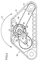
- FIG. 4 represents a side view of a tracked thruster of this second vehicle.
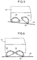
- FIG. 5 represents a view of this second vehicle on sloping ground.
- FIG. 6 represents a view of this second vehicle during a maneuver intended to raise the body of this vehicle.
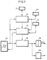
- FIG. 7 represents a block diagram of the device for measuring the displacement of this second vehicle.
- the element of the first vehicle receives a reference number less than 50 and the element of the second vehicle receives a reference number increased by 50 compared to the first.
- a vehicle comprises a vehicle body 2, 52 and a set of displacement members 4, 6, 8, 54, 56, 58 bearing on a ground 10, 60 to carry this body and allow it to be move.
- the vehicle further comprises a displacement measurement device itself comprising an odometric sensor 20, 70 for providing an odometric distance which is the distance traveled by the tread of the odometric member along its length on its raceway.
- the displacement members are constituted by four wheels, each provided with a suspension device.
- One of these wheels constitutes the odometric member 4 and its suspension member is symbolized by a telescopic support leg 19 sliding vertically without friction in the body 2, and by a spring 17 making it possible to maintain a permanent vertical bearing force. of the wheel on the ground despite irregularities such as 11 of it.
- the propulsion of this vehicle is assumed to be ensured by means not shown.
- the odometric sensor 20 measures the rotation of this wheel.
- the displacement members of the second example vehicle consist of four tracked thrusters such as 54.
- the track 62 constituting the tread of this thruster is driven by a drive pinion 100 itself driven by a chain 103 by an advance motor pinion 102 coupled to a motor (not shown) located in the body of the vehicle.
- the odometric sensor 70 measures the rotation of this drive pinion and can be arranged in the body of the vehicle.
- the displacement measurement device takes into account in a separate manner a continuous succession of said odometric distances.
- These odometric distances constitute primary elementary distances and are each traveled for a period of time corresponding to it.
- the contact tilt measurement means firstly comprise primary contact tilt measurement means 22, 72, 24, 74 for measuring a primary tilt angle which is that of the tangent to the raceway. at the point of contact 16, 66 with respect to a vehicle axis linked to the vehicle body 2, 52.
- This vehicle axis is parallel to a running plane j, k which is that in which the length of the running track extends. It is more particularly the longitudinal axis j along which the vehicle moves normally.
- These contact tilt measurement means then comprise an absolute orientation sensor 25, 75 to provide an orientation of said vehicle axis j with respect to at least one terrain axis such as x, y, or z linked to the terrain and constituting a said measurement axis.
- angular combination means 27, 76 combining the primary tilt angle with said orientation of the vehicle axis to provide the contact tilt angle.
- These angular combination means are symbolized by a circuit 27 of the first vehicle in FIG. 1.
- they are integrated into the displacement calculation means 76.
- Sensors such as 22 measure a horizontal force which, for example relative to the vertical force, is 1,732 times greater. A simple calculation then shows that the side of the obstacle 11 encountered by the wheel has an inclination of 60 degrees relative to the horizontal, that is to say that the angle of inclination of primary contact is 60 degrees . The corrected elementary distance is therefore, with respect to the measurement axis j, equal to half the primary elementary distance measured by the odometric sensor 20.
- This elementary distance is corrected a first time for this at 26. To provide a displacement in the field reference system, this elementary distance is also corrected a second time at 27 from the orientation information provided by an inertial unit 25.
- this second correction is carried out twice in parallel by multiplication by the cosine of the angle between the axis j and the axis x, and by the cosine of the angle between the j axis and the y axis.
- the elementary displacements corrected along these two axes are integrated into integration means 28 to provide the X and Y coordinates of the vehicle from an origin point.
- the displacement calculation means use on the one hand this primary displacement of the vehicle body, on the other hand, this orientation of the vehicle reference system to provide vehicle movements representative of the movement of the vehicle body in the field reference system.
- the link displacement sensor 124 provides a vector for the inclination speed of an odometric member oriented along the axis 120 and having a magnitude representative of the angular speed of the tilt movement.
- the running plane is perpendicular to this axis of inclination and meets this axis at a center of inclination 80. The raceway departs from a circle whose center would be this center of inclination.
- the contact tilt measurement means comprising the sensors 74 provide the position of the contact point 66 in the vehicle frame of reference.
- the displacement calculation means 76 use said tilt sensor vector and this contact point position to provide a relative speed of tilt center representative of the speed of movement of this tilt center with respect to the terrain. under the effect of said tilting movement in this vehicle reference system.
- This speed is the vector product of said odometric organ tilt vector by a vector joining the tilt center to the point of contact.
- An integration of this relative speed gives a relative inclination displacement which is added to the displacement of the rolling member to provide a said primary displacement of the vehicle body.
- the position and attitude of the vehicle body can only be completely known with the help of other information, for example by knowing the movements of three centers of inclination of three odometric bodies.
- the tilting movement is made possible by the fact that the core 64 of the odometric member 54 is rotatably mounted around a tubular hub 68 constituting the previously mentioned connecting member.
- the advance motor pinion 102 is driven from the body of the vehicle by a not shown advance shaft passing inside this hub.
- the tilting movement is also driven from the body of the vehicle by a tilting shaft passing inside the shaft of the feed shaft and carrying a tilting pinion gear 106 at the end. the latter drives, via a chain 108, a toothed wheel 110 rotating around an intermediate axis 112 linked to the core 64.
- the wheel 110 coaxially drives a toothed wheel of smaller diameter 114 driving a chain 116 which comes to take support on a toothed wheel 118 secured to the hub 68.
- the elements 106 to 118 constitute a tilt speed reducer.
- connection force sensors 72 are inserted into the hub 68 so that the forces transmitted by this hub pass through these sensors.
- the vehicle shown in fact comprises four odometric members such as 54, 56, and 58 to provide four primary elementary distances, respectively.
- the displacement calculation means 76 include odometric displacement calculation means for providing several corrected elementary distances from each of these primary elementary distances and for providing, from each of these distances, an estimate of elementary vehicle displacement representative of a movement of the vehicle body 52 during the corresponding period of time.
- the time periods considered are determined so that each such estimate of elementary vehicle movement constitutes an odometric speed estimate, and the inertial unit 75 provides, for each of these time periods, an inertial speed estimate obtained by integration. measures of acceleration and representative of at least one speed of this body.
- the displacement calculation means 76 are then supplemented by information fusion means 82 to effect a fusion of these odometric and inertial speed estimates so as to provide an overall speed estimate.
- These information fusion means 82 constitute for example at the same time a Kalman filter for filtering the odometric and inertial speed estimates. They provide separately on the one hand, using the integration means 78, the displacement of a point of the vehicle body, to enable the position of the vehicle to be known on the ground, on the other hand, before integration, with the help of a conversion device 104, the speeds of the various thrusters in the vehicle frame of reference.
Landscapes
- Engineering & Computer Science (AREA)
- Chemical & Material Sciences (AREA)
- Combustion & Propulsion (AREA)
- Transportation (AREA)
- Mechanical Engineering (AREA)
- Length Measuring Devices With Unspecified Measuring Means (AREA)
Claims (10)
- Vorrichtung zur Messung der Bewegung eines Fahrzeugs, insbesondere eines Roboters für schwieriges Gelände, wobei die Vorrichtung aufweist:- ein Rollband (12, 62), das eine Länge in einer geschlossenen Schleife bildet und so gestaltet ist, daß es in Längsrichtung bezüglich eines Geländes (10, 60) nicht gleitet, auf dem es aufliegt,- ein Streckenmeßorgan (4), das dieses Rollband trägt und führt und in Längsrichtung auf einem Rollweg umlaufen läßt, der durch dieses Organ gebildet wird und das Band auf das Gelände aufdrücken kann,- und eine Streckenmeßsonde (20, 70), um eine Streckenlänge zu liefern, die die von dem Rollband durchlaufene Strecke in Längsrichtung auf den Rollweg bildet, dadurch gekennzeichnet, daß die Vorrichtung weiter enthält:- Mittel zur Definition einer Meßachse (j),- Mittel zur Messung des Kontaktwinkels (22, 24, 72, 74), die einen Kontaktneigungswinkel liefern, der bezüglich der Meßachse den Neigungswinkel der Tangente zum Rollweg in einem Kontaktpunkt (16, 66) darstellt, in dem das Rollband auf dem Gelände aufliegt,- und Bewegungsrechenmittel (26, 76), die von der Streckenmeßsonde und von den Mitteln zur Winkelmessung gespeist werden und zumindest indirekt eine Multiplizierung dieser gemessenen Strecke mit dem Kosinus des Neigungswinkels durchführen, um eine für die Bewegung des Streckenmeßorgans bezüglich des Geländes entlang der Meßachse repräsentative korrigierte Strecke zu liefern.
- Vorrichtung nach Anspruch 1, bei der die Meßstrecke eine Elementarstrecke ist, die in einer entsprechenden Zeitdauer gemessen wird und bei der der Kontaktneigungswinkel während dieser entsprechenden Zeitdauer gemessen wird, wobei die korrigierte Strecke eine korrigierte Elementarstrecke entsprechend dieser Zeitdauer ist, dadurch gekennzeichnet, daß die Vorrichtung weiter Integrationsmittel (26, 76) aufweist, um die Summe von korrigierten Elementarstrecken entsprechend einer Anzahl von Zeitdauern zu liefern, die eine kontinuierliche Folge ab einem Ursprungszeitpunkt bis zum Meßzeitpunkt bilden, so daß diese Summe für die Verschiebung des Streckenmeßorgans (4, 54) entlang der Meßachse (j) zwischen diesen beiden Zeitpunkten repräsentativ ist.
- Fahrzeug, insbesondere ein Roboter für schwieriges Gelände,- mit einem Fahrzeugkörper (2, 52),- und mit einer Gruppe von Bewegungsorganen (4, 6, 8, 54, 56, 58), die sich auf dem Gelände (10, 60) abstützen, um den Körper zu tragen und ihn zu verschieben, wobei mindestens ein Organ dieser Gruppe ein Streckenmeßorgan (4, 54) bildet, das aufweist:- ein Rollband (12, 62) mit einer bestimmten Länge in geschlossener Schleife, das so gestaltet ist, daß es in Längsrichtung bezüglich des Geländes nicht gleitet, wenn es auf diesem aufliegt,- einen Kern (14, 64), der einen Rollweg für dieses Rollband bildet, um das Band zu halten und in seiner Längsrichtung auf diesem Weg umlaufen zu lassen, wobei dieser Rollweg das Band auf das Gelände in einem Kontaktpunkt (16, 66) aufdrückt,- und ein Verbindungsorgan (18, 19, 68), das diesen Kern mit dem Fahrzeugkörper verbindet,- wobei das Fahrzeug weiter eine Vorrichtung zur Bewegungsmessung aufweist, zu der eine Streckenmeßsonde (20, 70) gehört, um eine gemessene Streckenlänge zu liefern, die die von dem Rollband des Streckenmeßorgans in seiner Längsrichtung auf dem Rollweg durchlaufene Strecke ist, dadurch gekennzeichnet, daß die Vorrichtung zur Bewegungsmessung zur getrennten Messung einer kontinuierlichen Folge von Elementarstrecken ausgebildet ist, die primäre Elementarstrecken bilden und während je einer der entsprechenden Zeitdauern durchfahren werden, wobei diese Zeitdauern kontinuierlich ab einem Ursprungszeitpunkt bis zu einem Meßzeitpunkt aufeinanderfolgen,- wobei die Bewegungsmeßvorrichtung weiter aufweist- Mittel, um mindestens eine Meßachse zu definieren,- Mittel zur Messung des Kontaktwinkels (22, 24, 25, 72, 74), die in jeder Zeitdauer einen Kontaktneigungswinkel messen, der der Winkel der Tangente des Rollwegs im Kontaktpunkt bezüglich einer der Meßachsen x, y, z) während dieser Zeitdauer ist,- und Bewegungsrechenmittel, die enthalten:- - Mittel zur Streckenlängenkorrektur (26, 27, 76), um jede primäre Elementarstreckenlänge mit einem Koeffizienten gleich dem Kosinus des entsprechenden Neigungswinkels zu multiplizieren, so daß sich eine korrigierte Elementarstreckenlänge ergibt, die für die Bewegung des Streckenmeßorgans bezüglich des Geländes während dieser entsprechenden Zeitdauer entlang der Meßachse repräsentativ ist,- - und Integrationsmittel (28, 78), um die Summe dieser korrigierten Elementarstrecken zu liefern, die eine Bewegung des Streckenmeßorgans wiedergibt, wobei die Bewegung entlang der Meßachse zwischen dem Ursprungszeitpunkt und dem Meßzeitpunkt gemessen wird.
- Fahrzeug nach Anspruch 3, in dem die Mittel zur Messung des Kontaktwinkels Mittel zur Messung des primären Kontaktwinkels (22, 72) enthalten, die einen primären Neigungswinkel messen, der der Tangente an den Rollweg im Kontaktpunkt (16, 66) bezüglich einer mit dem Fahrzeugkörper (62, 52) verbundenen Fahrzeugachse (j) bildet.
- Fahrzeug nach Anspruch 4, dadurch gekennzeichnet, daß die Mittel zur Messung des Kontaktwinkels außerdem mindestens eine Orientierungssonde (25, 75) aufweisen, die eine Orientierung der Fahrzeugachse (j) bezüglich eines Gelände-Bezugssystems (x, y, z) liefert, das mindestens eine mit dem Gelände verknüpfte Achse (60) enthält, die die Meßachse bildet, und daß weiter Winkelkombinationsmittel (27, 76) vorgesehen sind, um den primären Neigungswinkel mit der Orientierung der Fahrzeugachse zu kombinieren und den Kontaktneigungswinkel zu liefern.
- Fahrzeug nach Anspruch 4, in dem der Rollweg (12, 62) eine Schleife in einer Rollebene (j, k) bildet, wobei die Fahrzeugachse (j) sich in dieser Ebene befindet.
- Fahrzeug nach Anspruch 4, dadurch gekennzeichnet, daß die Mittel zur Messung des primären Kontaktwinkels aufweisen:- mindestens eine Verbindungskraftmeßsonde (22, 72), die einen Meßwert der Verbindungskraft liefert, der mindestens teilweise ein System von Verbindungskräften darstellt, die von dem Verbindungsorgan zwischen dem Kern (14, 64) des Streckenmeßorgans und dem Fahrzeugkörper (2, 52) übertragen werden,- und primäre Neigungsrechenmittel (24, 74), die diesen Verbindungskraftmeßwert verwenden, um den primären Kontaktneigungswinkel zu liefern.
- Fahrzeug nach Anspruch 3, in dem das Verbindungsorgan (68) Bewegungen des Fahrzeugkörpers (2, 52) bezüglich des Streckenmeßorgans (4, 54) erlaubt, dadurch gekennzeichnet, daß es aufweist:- mindestens eine Verbindungsbewegungssonde (124), um mindestens indirekt eine Relativbewegung des Fahrzeugkörpers bezüglich des Kerns (64) des Streckenmeßorgans (54) in einem Fahrzeugbezugssystems (i, j, k) zu messen, das mit dem Fahrzeugkörper verbunden ist und aus den Meßachsen besteht,- Rechenmittel (76), um diese Relativbewegung des Fahrzeugkörpers zur Bewegung des Streckenmeßorgans in dem Fahrzeugbezugssystem zu addieren, so daß sich eine primäre Bewegung des Fahrzeugkörpers im Fahrzeugbezugssystem ergibt,- und eine Orientierungssonde (25, 75), um eine Ausrichtung dieses Fahrzeugbezugssystems zu einem mit dem Gelände verknüpften Bezugssystem zu liefern, das aus mindestens zwei Geländeachsen besteht, die weitere Meßachsen bilden,- wobei die Bewegungsrechenmittel (76) einerseits die primäre Bewegung des Fahrzeugkörpers und andererseits die Ausrichtung des Fahrzeugbezugssystems verwenden, um eine Bewegung des Fahrzeugs zu liefern, die für die Bewegung des Fahrzeugkörpers im Geländebezugssystem repräsentativ ist.
- Fahrzeug nach Anspruch 3, dadurch gekennzeichnet, daß es mehrere Streckenmeßorgane (54, 56, 58) aufweist, um mehrere primäre Meßstrecken zu liefern, und daß die Bewegungsrechenmittel auf der Streckenmessung beruhende Rechenmittel (76) aufweisen, um mehrere korrigierte Elementarstrecken ausgehend von den primären Elementarstrecken zu liefern und ausgehend von jeder der Strecken eine Abschätzung der Elementarbewegung des Fahrzeugs entsprechend einer Bewegung des Fahrzeugkörpers (52) während der entsprechenden Zeitdauer zu liefern, wobei diese Zeitdauer so bestimmt ist, daß jede derartige Abschätzung der Elementarbewegung des Fahrzeugs eine Abschätzung der auf der Streckenmessung beruhenden Geschwindigkeit ist, und daß der Fahrzeugkörper eine Trägheitszentrale (75) trägt, die für jede Zeitdauer aufgrund von Beschleunigungsmessungen eine Geschwindigkeitsabschätzung auf der Basis der Trägheitsmessung liefert, die für mindestens eine Geschwindigkeit des Körpers repräsentativ ist, wobei die Bewegungsrechenmittel weiter Mittel zur Kombination von Informationen (28) aufweisen, die die Schätzwerte der aufgrund der Streckenmessung und aufgrund der Beschleunigungsmessung erhaltenen Schätzwerte kombinieren, so daß sich eine globale Geschwindigkeitsabschätzung ergibt.
- Fahrzeug nach Anspruch 9, in dem die Mittel zur Kombination von Informationen (82) ein Kalman-Filter bilden, um die auf der Streckenmessung und der Beschleunigungsmessung beruhenden Schätzungen zu filtern.
Applications Claiming Priority (2)
| Application Number | Priority Date | Filing Date | Title |
|---|---|---|---|
| FR9207439A FR2692667B1 (fr) | 1992-06-18 | 1992-06-18 | Dispositif de mesure de déplacement pour véhicule, notamment pour robot tout-terrain, et véhicule équipé d'un tel dispositif. |
| FR9207439 | 1992-06-18 |
Publications (2)
| Publication Number | Publication Date |
|---|---|
| EP0575240A1 EP0575240A1 (de) | 1993-12-22 |
| EP0575240B1 true EP0575240B1 (de) | 1995-08-02 |
Family
ID=9430905
Family Applications (1)
| Application Number | Title | Priority Date | Filing Date |
|---|---|---|---|
| EP93401528A Expired - Lifetime EP0575240B1 (de) | 1992-06-18 | 1993-06-15 | Entfernungsmessgerät für ein Fahrzeug, insbesondere für einen geländegängigen Roboter und mit solch einem Gerät ausgerüstetes Fahrzeug |
Country Status (4)
| Country | Link |
|---|---|
| US (1) | US5410478A (de) |
| EP (1) | EP0575240B1 (de) |
| DE (1) | DE69300324T2 (de) |
| FR (1) | FR2692667B1 (de) |
Families Citing this family (13)
| Publication number | Priority date | Publication date | Assignee | Title |
|---|---|---|---|---|
| DE29501258U1 (de) * | 1995-01-27 | 1995-03-09 | Breest, Ernst-Jürgen, 90547 Stein | Reinigungsgerät, insbesondere Wisch- bzw. Schrubbmop |
| US5987378A (en) * | 1996-10-24 | 1999-11-16 | Trimble Navigation Limited | Vehicle tracker mileage-time monitor and calibrator |
| US6671589B2 (en) * | 2001-02-13 | 2003-12-30 | William Holst | Method and apparatus to support remote and automatically initiated data loading and data acquisition of airborne computers using a wireless spread spectrum aircraft data services link |
| US7609156B2 (en) | 2004-04-07 | 2009-10-27 | Jeffrey D Mullen | Advanced cooperative defensive military tactics, armor, and systems |
| FR2878954B1 (fr) * | 2004-12-07 | 2007-03-30 | Sagem | Systeme de navigation inertielle hybride base sur un modele cinematique |
| US8244431B2 (en) * | 2009-02-13 | 2012-08-14 | Microsoft Corporation | Determining velocity using multiple sensors |
| JOP20200120A1 (ar) | 2013-10-21 | 2017-06-16 | Esco Group Llc | إزالة وتركيب تجميعة تآكل |
| WO2017218591A1 (en) | 2016-06-13 | 2017-12-21 | Esco Corporation | Handling system for ground-engaging wear parts secured to earth working equipment |
| CN109159117A (zh) * | 2018-08-22 | 2019-01-08 | 北京云迹科技有限公司 | 一种位置校准方法和送货机器人 |
| US11679639B2 (en) * | 2018-10-23 | 2023-06-20 | Caterpillar Paving Products Inc. | Systems and methods for controlling ground inclination of rotary cutting machines |
| PE20211717A1 (es) | 2018-12-10 | 2021-09-03 | Esco Group Llc | Sistema y proceso para conducir operaciones en el campo |
| US12379228B2 (en) * | 2020-12-16 | 2025-08-05 | Randy L. Tiede | Trailer odometer |
| SE547667C2 (en) * | 2022-07-04 | 2025-11-04 | Husqvarna Ab | Improved determination of pose for a robotic work tool |
Family Cites Families (8)
| Publication number | Priority date | Publication date | Assignee | Title |
|---|---|---|---|---|
| US4223753A (en) * | 1977-12-19 | 1980-09-23 | Bradbury Harold M | Omni-directional transport device |
| DE3143234A1 (de) * | 1981-10-31 | 1983-05-11 | Teldix Gmbh, 6900 Heidelberg | Navigationsverfahren |
| FR2609335B1 (fr) * | 1987-01-05 | 1989-04-14 | Protee | Systeme de reperage du mouvement d'un vehicule a chenilles |
| FR2610885B1 (fr) * | 1987-02-18 | 1991-07-12 | Protee | Vehicule motorise a chenilles avec bras articules pour franchissement d'obstacles |
| US5287280A (en) * | 1987-09-14 | 1994-02-15 | Kabushiki Kaisha Komatsu Seisakusho | Method and apparatus for controlling shoe slip of crawler vehicle |
| FR2653731B1 (fr) * | 1989-10-31 | 1992-01-03 | Alsthom Cge Alcatel | Procede de determination de parametres d'appui d'un vehicule et vehicule d'intervention pour sols accidentes. |
| US5248007A (en) * | 1989-11-21 | 1993-09-28 | Quest Technologies, Inc. | Electronic control system for stair climbing vehicle |
| US5337846A (en) * | 1990-08-08 | 1994-08-16 | Kabushiki Kaisha Komatsu Seisakusho | Disaster relief robot and operation controller therefor |
-
1992
- 1992-06-18 FR FR9207439A patent/FR2692667B1/fr not_active Expired - Fee Related
-
1993
- 1993-06-15 DE DE69300324T patent/DE69300324T2/de not_active Expired - Fee Related
- 1993-06-15 EP EP93401528A patent/EP0575240B1/de not_active Expired - Lifetime
- 1993-06-16 US US08/077,039 patent/US5410478A/en not_active Expired - Fee Related
Also Published As
| Publication number | Publication date |
|---|---|
| FR2692667B1 (fr) | 1994-08-19 |
| EP0575240A1 (de) | 1993-12-22 |
| DE69300324T2 (de) | 1996-01-04 |
| FR2692667A1 (fr) | 1993-12-24 |
| DE69300324D1 (de) | 1995-09-07 |
| US5410478A (en) | 1995-04-25 |
Similar Documents
| Publication | Publication Date | Title |
|---|---|---|
| EP0575240A1 (de) | Entfernungsmessgerät für ein Fahrzeug, insbesondere für einen geländegängigen Roboter und mit solch einem Gerät ausgerüstetes Fahrzeug | |
| EP0277447B1 (de) | System zur Ermittlung der Bewegung eines Raupenfahrzeuges | |
| FR3012231A1 (fr) | Dispositif et procede de reperage de terrain en vol pour microdrone | |
| EP2694375B1 (de) | Vorrichtung und verfahren zur lagebestimmung eines satelliten, und satellit mit einer solchen vorrichtung | |
| CA2091613C (fr) | Procede et dispositif pour la determination de la position et de la trajectoire relatives de deux vehicules spatiaux | |
| FR2559118A1 (fr) | Systeme de direction pour vehicules prenant en compte les courses d'amortissement des suspensions | |
| CA2046433A1 (fr) | Vehicule a propulseurs motorises | |
| EP0426079B1 (de) | Ermittlungsverfahren der Stützparameter eines Fahrzeuges und Einsatzfahrzeug für unebenes Gelände | |
| EP1324889B1 (de) | Verfahren zur automatischen ortung von den links- und rechtsrädern eines kraftfahrzeuges | |
| FR2697081A1 (fr) | Codeur à large étendue de mesure, destiné à la détermination de la position d'une pièce dans une course d'amplitude prédéterminée, telle qu'un accessoire de véhicule. | |
| EP0336828B1 (de) | Molch zum Messen der topographischen Anordnung einer nicht frei zugänglichen Rohrleitung | |
| EP0427999B1 (de) | Einsatzfahrzeug mit variabler Konfiguration für unebenes Gelände | |
| FR2627602A1 (fr) | Procede et dispositif pour l'estimation des parametres du modele geometrique d'un manipulateur | |
| EP0426555B1 (de) | Fahrzeug für Einsätze, insbesondere in Gebäuden | |
| EP0631111B1 (de) | Verfahren und Vorrichtung zum Bestimmen der Position eines Flugkörpers | |
| CA2028984A1 (fr) | Vehicule d'intervention a propulseurs inclinables | |
| EP0189721B1 (de) | Verfahren und Vorrichtung zur Messung des Einschlagwinkels eines Kraftfahrzeugvorderrades | |
| CA2046467A1 (fr) | Vehicule d'intervention a propulseurs inclinables | |
| WO2004091399A1 (fr) | Procede et dispositif autonome pour la determination de la position relative de deux objets en mouvement dans un plan ou dans l’espace | |
| EP0717264A1 (de) | Verfahren und Vorrichtung zum Schätzen von gyrometrischen Nullpunktabweichungen | |
| EP2326999B1 (de) | Navigationsverfahren und system zum implementieren eines solchen verfahrens | |
| EP3884238A1 (de) | Trägheitsmessvorrichtung | |
| EP3857186A1 (de) | Verfahren und vorrichtung zur bestimmung mindestens einer trägheitseigenschaft eines objekts | |
| FR3073486A1 (fr) | Dispositif et procede de localisation le long d'un rail creux rectiligne | |
| FR2638727A1 (fr) | Dispositif de transport en continu a vitesse variable et debit de surface constant |
Legal Events
| Date | Code | Title | Description |
|---|---|---|---|
| PUAI | Public reference made under article 153(3) epc to a published international application that has entered the european phase |
Free format text: ORIGINAL CODE: 0009012 |
|
| AK | Designated contracting states |
Kind code of ref document: A1 Designated state(s): DE FR GB IT |
|
| 17P | Request for examination filed |
Effective date: 19940422 |
|
| 17Q | First examination report despatched |
Effective date: 19950116 |
|
| GRAA | (expected) grant |
Free format text: ORIGINAL CODE: 0009210 |
|
| AK | Designated contracting states |
Kind code of ref document: B1 Designated state(s): DE FR GB IT |
|
| ITF | It: translation for a ep patent filed | ||
| REF | Corresponds to: |
Ref document number: 69300324 Country of ref document: DE Date of ref document: 19950907 |
|
| GBT | Gb: translation of ep patent filed (gb section 77(6)(a)/1977) |
Effective date: 19950915 |
|
| PLBE | No opposition filed within time limit |
Free format text: ORIGINAL CODE: 0009261 |
|
| STAA | Information on the status of an ep patent application or granted ep patent |
Free format text: STATUS: NO OPPOSITION FILED WITHIN TIME LIMIT |
|
| 26N | No opposition filed | ||
| REG | Reference to a national code |
Ref country code: FR Ref legal event code: CD |
|
| REG | Reference to a national code |
Ref country code: GB Ref legal event code: IF02 |
|
| PGFP | Annual fee paid to national office [announced via postgrant information from national office to epo] |
Ref country code: GB Payment date: 20030530 Year of fee payment: 11 |
|
| PGFP | Annual fee paid to national office [announced via postgrant information from national office to epo] |
Ref country code: DE Payment date: 20030603 Year of fee payment: 11 |
|
| PGFP | Annual fee paid to national office [announced via postgrant information from national office to epo] |
Ref country code: FR Payment date: 20030611 Year of fee payment: 11 |
|
| PG25 | Lapsed in a contracting state [announced via postgrant information from national office to epo] |
Ref country code: GB Free format text: LAPSE BECAUSE OF NON-PAYMENT OF DUE FEES Effective date: 20040615 |
|
| PG25 | Lapsed in a contracting state [announced via postgrant information from national office to epo] |
Ref country code: DE Free format text: LAPSE BECAUSE OF NON-PAYMENT OF DUE FEES Effective date: 20050101 |
|
| GBPC | Gb: european patent ceased through non-payment of renewal fee |
Effective date: 20040615 |
|
| PG25 | Lapsed in a contracting state [announced via postgrant information from national office to epo] |
Ref country code: FR Free format text: LAPSE BECAUSE OF NON-PAYMENT OF DUE FEES Effective date: 20050228 |
|
| REG | Reference to a national code |
Ref country code: FR Ref legal event code: ST |
|
| PG25 | Lapsed in a contracting state [announced via postgrant information from national office to epo] |
Ref country code: IT Free format text: LAPSE BECAUSE OF NON-PAYMENT OF DUE FEES;WARNING: LAPSES OF ITALIAN PATENTS WITH EFFECTIVE DATE BEFORE 2007 MAY HAVE OCCURRED AT ANY TIME BEFORE 2007. THE CORRECT EFFECTIVE DATE MAY BE DIFFERENT FROM THE ONE RECORDED. Effective date: 20050615 |