EP0575231B1 - Dispositif de stabilisation d'un moyen de coupe pour la pose d'une prothèse en chirurgie osseuse - Google Patents
Dispositif de stabilisation d'un moyen de coupe pour la pose d'une prothèse en chirurgie osseuse Download PDFInfo
- Publication number
- EP0575231B1 EP0575231B1 EP93401511A EP93401511A EP0575231B1 EP 0575231 B1 EP0575231 B1 EP 0575231B1 EP 93401511 A EP93401511 A EP 93401511A EP 93401511 A EP93401511 A EP 93401511A EP 0575231 B1 EP0575231 B1 EP 0575231B1
- Authority
- EP
- European Patent Office
- Prior art keywords
- rod
- bone
- cutting means
- thread
- prosthesis
- Prior art date
- Legal status (The legal status is an assumption and is not a legal conclusion. Google has not performed a legal analysis and makes no representation as to the accuracy of the status listed.)
- Expired - Lifetime
Links
- 210000000988 bone and bone Anatomy 0.000 title claims description 30
- 238000005520 cutting process Methods 0.000 title claims description 30
- 238000001356 surgical procedure Methods 0.000 title claims description 7
- 230000000087 stabilizing effect Effects 0.000 title description 3
- 230000003019 stabilising effect Effects 0.000 claims 1
- 238000004873 anchoring Methods 0.000 description 9
- 210000000689 upper leg Anatomy 0.000 description 7
- 210000003127 knee Anatomy 0.000 description 4
- 230000006641 stabilisation Effects 0.000 description 4
- 238000011105 stabilization Methods 0.000 description 4
- 238000000605 extraction Methods 0.000 description 3
- 238000009434 installation Methods 0.000 description 3
- 238000000034 method Methods 0.000 description 3
- 230000006835 compression Effects 0.000 description 2
- 238000007906 compression Methods 0.000 description 2
- 229910000831 Steel Inorganic materials 0.000 description 1
- 230000001066 destructive effect Effects 0.000 description 1
- 230000000694 effects Effects 0.000 description 1
- 230000003100 immobilizing effect Effects 0.000 description 1
- 210000002414 leg Anatomy 0.000 description 1
- 238000003754 machining Methods 0.000 description 1
- 230000000149 penetrating effect Effects 0.000 description 1
- 230000000284 resting effect Effects 0.000 description 1
- 125000006850 spacer group Chemical group 0.000 description 1
- 239000010959 steel Substances 0.000 description 1
Images
Classifications
-
- A—HUMAN NECESSITIES
- A61—MEDICAL OR VETERINARY SCIENCE; HYGIENE
- A61B—DIAGNOSIS; SURGERY; IDENTIFICATION
- A61B17/00—Surgical instruments, devices or methods
- A61B17/14—Surgical saws
- A61B17/15—Guides therefor
-
- A—HUMAN NECESSITIES
- A61—MEDICAL OR VETERINARY SCIENCE; HYGIENE
- A61B—DIAGNOSIS; SURGERY; IDENTIFICATION
- A61B17/00—Surgical instruments, devices or methods
- A61B17/14—Surgical saws
- A61B17/15—Guides therefor
- A61B17/154—Guides therefor for preparing bone for knee prosthesis
- A61B17/155—Cutting femur
-
- A—HUMAN NECESSITIES
- A61—MEDICAL OR VETERINARY SCIENCE; HYGIENE
- A61B—DIAGNOSIS; SURGERY; IDENTIFICATION
- A61B17/00—Surgical instruments, devices or methods
- A61B17/56—Surgical instruments or methods for treatment of bones or joints; Devices specially adapted therefor
- A61B17/58—Surgical instruments or methods for treatment of bones or joints; Devices specially adapted therefor for osteosynthesis, e.g. bone plates, screws or setting implements
- A61B17/68—Internal fixation devices, including fasteners and spinal fixators, even if a part thereof projects from the skin
- A61B17/72—Intramedullary devices, e.g. pins or nails
-
- A—HUMAN NECESSITIES
- A61—MEDICAL OR VETERINARY SCIENCE; HYGIENE
- A61B—DIAGNOSIS; SURGERY; IDENTIFICATION
- A61B17/00—Surgical instruments, devices or methods
- A61B17/56—Surgical instruments or methods for treatment of bones or joints; Devices specially adapted therefor
- A61B17/58—Surgical instruments or methods for treatment of bones or joints; Devices specially adapted therefor for osteosynthesis, e.g. bone plates, screws or setting implements
- A61B17/68—Internal fixation devices, including fasteners and spinal fixators, even if a part thereof projects from the skin
- A61B17/84—Fasteners therefor or fasteners being internal fixation devices
- A61B17/86—Pins or screws or threaded wires; nuts therefor
Definitions
- the present invention relates to a device for axially stabilizing a cutting means used to make at least one cut at one end of a bone for the purpose of placing a prosthesis in bone surgery. It also relates to tools intended for use in bone surgery.
- the invention finds a particularly advantageous, but not exclusive, application in the field of fitting knee prostheses
- a tool called ancillary equipment
- ancillary equipment making it possible to prepare the installation of the prosthesis itself.
- a femoral knee prosthesis having a certain number of flat internal contact surfaces
- corresponding cuts must be made at the distal end of the femur so as to guarantee perfect placement of the prosthesis on the bone well laid out.
- a cutting means template or multi-cut box, which must be kept in a stable position at the distal end of the femur.
- the technique usually used consists in piercing the femoral intercondylar notch to partially introduce into the intramedullary canal a centering rod, called centro-medullary, intended to receive said cutting means.
- This process effectively ensures satisfactory centering of the cutting means.
- the centering rod is implanted directly in the bone, the axial stability of the rod, and therefore of the cutting means, The structure of the bone in this place is very variable: either relatively compact, or disorganized and therefore without mechanical resistance.
- harpoon-type anchoring means constituted by toothed fins.
- EP-A-243 109 and US-A-4 487 203 disclose devices for making cuts at the end of a bone, in each case comprising an intramedullary centering rod.
- the American patent however provides a means of stabilizing the cutting means with respect to the centering rod which is, in this case, not straight.
- the end of the bent proximal part of this rod is in fact fixed to the cutting box by a screw whose function is simply to secure the rod to the box.
- the technical problem to be solved by the object of the present invention is to provide a device for axial stabilization of a cutting means used to make at least one cut at one end of a bone for the purpose of placing a prosthesis in bone surgery, said device comprising a centering means, constituted by a centering rod, partially introduced in said bone and intended to receive said cutting means, a means for applying and compressing said cutting means against the end of the bone being mounted at the proximal end of the centering rod, a device which would allow to obtain perfect stability of the cutting means in the axial direction while ensuring extraction of the stem without damage to the bone tissues.
- the solution to the technical problem posed consists, according to the present invention, in that said centering rod is provided with an anchoring thread so as to produce a lag screw stabilized axially in a direction parallel to the axis of the rod .
- the anchoring thread with which the rod is provided guarantees perfect axial stability of the cutting means and the extraction of the rod forming a lag screw is carried out very simply by unscrewing the rod without this operation involving bone damage.
- the device according to the invention can be implemented with all types of cutting means, whether single cut jigs placed successively on the same lag screw, or even a single box making it possible to perform all required cuts.
- said device also comprises a means of application and axial compression of said cutting means against the end of the bone, that is to say a means the action of which is directed parallel to the axis of the rod penetrating into the intramedullary canal, so as to cooperate with the anchoring thread of the centering rod in order to ensure maximum stabilization of the cutting means.
- a means of application and axial compression of said cutting means against the end of the bone that is to say a means the action of which is directed parallel to the axis of the rod penetrating into the intramedullary canal, so as to cooperate with the anchoring thread of the centering rod in order to ensure maximum stabilization of the cutting means.
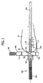
- Figure 1 is a sectional view of a tool for placing a knee prosthesis comprising a longitudinal stabilization device according to the invention.
- FIG. 1 shows, in section, a tool, also called ancillary equipment, for the installation of a femoral knee prosthesis.
- This ancillary equipment comprises a cutting means 100 which in the example of FIG. 1 is a case allowing a plurality of cuts to be made at the end 20 of a bone 10, here the femur, using slots 110, 120, 130, 140 through which is successively placed an oscillating saw not shown.
- the case 100 of femoral cut includes posterior legs 150 which are supported on the posterior condyles 21 of the femur 10 by actuating a knurled screw 160 for anteroposterior adjustment.
- the delivery ancillary comprises an axial stabilization device for the housing 100, comprising an intramedullary rod 200 for centering partially introduced into the central medullary canal of the femur 10 and intended to receive the housing 100 of femoral cut .
- the rod 200 is provided with a thread 210 for anchoring, thus producing a lag screw stabilized axially in a direction parallel to the axis of the rod 200.
- the housing 100 is therefore perfectly centered relative to the axis of the femur 10 and, to stabilize it in the axial direction, it is sufficient to secure it with the rod 200 forming a lag screw.
- the device illustrated in FIG. 1 also includes means 300 for applying and compressing the case 100 of femoral cut against the end 20 of the bone 10.
- said means 300 for axial application and compression is constituted by a knurled screw 320 mounted at the proximal end of the lag screw 200 and driving a spacer 310 intended to come resting against the cutting unit 100.
- said anchoring thread 210 is arranged in the proximal part of the rod 200 forming a lag screw, the distal length of the rod serving as a guide means through the central medullary canal.
- the length of the thread is between 10 and 50% of the lag screw 200. Due to its limited length, it is preferable to provide a form of thread capable of providing an anchoring volume capable of immobilizing the axially rod 200 in the bone 10. For this purpose, it is proposed a thread thickness e small in front of the pitch p, the ratio e / p having to be at most equal to 25%. This produces a net having a very fine cutting edge with a space capable of accommodating a sufficient bone stock taking into account that the medium in which the lag screw 200 is introduced, is relatively not very resistant.
- the threading is carried out for example by machining a rod of austenitic steel with thermal hardening.
Landscapes
- Health & Medical Sciences (AREA)
- Surgery (AREA)
- Life Sciences & Earth Sciences (AREA)
- Heart & Thoracic Surgery (AREA)
- Molecular Biology (AREA)
- Oral & Maxillofacial Surgery (AREA)
- Engineering & Computer Science (AREA)
- Biomedical Technology (AREA)
- Dentistry (AREA)
- Medical Informatics (AREA)
- Nuclear Medicine, Radiotherapy & Molecular Imaging (AREA)
- Animal Behavior & Ethology (AREA)
- General Health & Medical Sciences (AREA)
- Public Health (AREA)
- Veterinary Medicine (AREA)
- Prostheses (AREA)
- Surgical Instruments (AREA)
Description
- La présente invention concerne un dispositif de stabilisation axiale d'un moyen de coupe utilisé pour effectuer au moins une coupe à une extrêmité d'un os en vue de la pose d'une prothèse en chirurgie osseuse. Elle concerne également un outillage destiné à être utilisé en chirurgie osseuse.
- L'invention trouve une application particulièrement avantageuse, mais non exclusive, dans le domaine de la pose de prothèses du genou
- D'une manière générale, la pose d'une prothèse en chirurgie osseuse exige la mise en oeuvre d'un outillage, dit matériel ancillaire, permettant de préparer la pose de la prothèse proprement dite. Dans le cas d'une prothèse fémorale du genou présentant un certain nombre de surfaces de contact internes planes, il faut effectuer à l'extrémité distale du fémur des coupes correspondantes de façon à garantir une mise en place parfaite de la prothèse sur l'os ainsi aménagé. Dans ce but, on utilise un moyen de coupe, gabarit ou boitier multicoupe, qui doit être maintenu en position stable à l'extrémité distale du fémur. La technique habituellement employée consiste à percer l'échancrure intercondyliaire fémorale pour introduire partiellement dans le canal intra-médullaire une tige de centrage, dite centro-médullaire, destinée à reçevoir ledit moyen de coupe. Ce procédé assure effectivement un centrage satisfaisant du moyen de coupe. Toutefois, compte tenu du fait que ladite tige de centrage est implantée directement dans l'os, la stabilité axiale de la tige,et donc du moyen de coupe, n'est pas suffisante.En effet, la structure de l'os en cet endroit est très variable: soit relativement compacte, soit désorganisée et donc sans résistance mécanique.
- Pour remédier à cette difficulté, on a recours à diverses méthodes connues.Il s'agit par exemple du brochage du moyen de coupe sur la partie distale du fémur qui permet de maintenir en position ledit moyen de coupe sans pourtant réaliser un véritable appui contre l'os, ce qui a pour inconvénient de rendre possible le déplacement du moyen de coupe sous l'effet des vibrations produites par les scies oscillantes utilisées lors des opérations de coupe.
- On peut également munir la tige de centrage de moyens d'ancrage du type harpon constitués par des ailettes dentées.Outre le fait qu'il est peu fiable au niveau de l'ancrage, un tel système a le désavantage d'être destructif puisque l'extraction de la tige se fait par arrachage.
- On connaît des documents EP-A-243 109 et US-A-4 487 203 des dispositifs pour effectuer des coupes à l'extrémité d'un os, comportant dans chaque cas une tige de centrage intra-médullaire.
- Le brevet américain prévoit cependant un moyen de stabilisation du moyen de coupe par rapport à la tige de centrage qui est, dans ce cas là, non rectiligne. L'extrémité de la partie proximale coudée de cette tige est en effet fixée au boîtier de coupe par une vis dont la fonction est simplement de solidariser la tige au boîtier.
- Aussi, le problème technique à résoudre par l'objet de la présente invention est de proposer un dispositif de stabilisation axiale d'un moyen de coupe utilisé pour effectuer au moins une coupe à une extrémité d'un os en vue de la pose d'une prothèse en chirugie osseuse , ledit dispositif comportant un moyen de centrage, constitué par une tige de centrage, introduite partiellement dans ledit os et destinée à reçevoir ledit moyen de coupe, un moyen d'application et de mise en compression dudit moyen de coupe contre l'extrémité de l'os étant monté à l'extrémité proximale de la tige de centrage, dispositif qui permettrait d'obtenir une stabilité parfaite du moyen de coupe dans le sens axial tout en assurant une extraction de la tige sans dommage pour les tissus osseux .
- La solution au problème technique posé consiste, selon la présente invention , en ce que ladite tige de centrage est munie d'un filetage d'ancrage de manière à réaliser un tire-fond stabilisé axialement dans une direction parallèle à l'axe de la tige.
- Ainsi,le filetage d'ancrage dont est munie la tige garantit une stabilité axiale parfaite du moyen de coupe et l'extraction de la tige formant tire-fond est réalisée de façon très simple par dévissage de la tige sans que cette opération n'entraîne de dégâts osseux.
- Bien entendu,le dispositif conforme à l'invention peut-être mis en oeuvre avec tous types de moyen de coupe, que ce soit des gabarits à coupe unique placés successivement sur le même tire-fond, ou encore un seul boitier permettant d'effectuer toutes les coupes requises.
- Ce dernier moyen de coupe est particulièrement avantageux puisqu'il assure une corrélation idéale des coupes successives. Pour obtenir un résultat parfait, il suffit de maintenir le moyen de coupe dans une position axiale déterminée. Pour cela, il est prévu, selon l'invention,que ledit dispositif comporte également un moyen d'application et de mise en compression axiales dudit moyen de coupe contre l'extrémité de l'os, c'est-à-dire un moyen dont l'action est dirigée parallèlement à l'axe de la tige pénétrant dans le canal intra-médullaire, de manière à coopérer avec le filetage d'ancrage de la tige de centrage afin d'assurer une stabilisation maximale du moyen de coupe. Celui-ci étant ainsi maintenu en permanence en appui contre l'os, il constitue une référence géométrique fixe pour réaliser les coupes successives.
- La description qui va suivre en regard du dessin annexé, donné à titre d'exemple non limitatif, fera bien comprendre en quoi consiste l'invention et comment elle peut être réalisée.
- La figure 1 est une vue en coupe d'un outillage de pose de prothèse fémorale du genou comportant un dispositif de stabilisation longitudinale conforme à l'invention.
- La figure 1 montre, en coupe, un outillage ,appelé aussi matériel ancillaire, pour la pose d'une prothèse fémorale du genou. Ce matériel ancillaire comporte un moyen 100 de coupe qui dans l'exemple de la figure 1 est un boitier permettant de réaliser une pluralité de coupes à l'extrémité 20 d'un os 10, ici le fémur, à l'aide de fentes 110, 120, 130, 140 à travers lesquelles est placée successivement une scie oscillante non représentée. On notera que le boitier 100 de coupe fémoral comporte des pattes postérieures 150 qui sont mises en appui sur les condyles postérieurs 21 du fémur 10 en actionnant une vis molettée 160 de réglage antéro-postérieur.
- Comme le montre la figure 1,l'ancillaire de pose comprend un dispositif de stabilisation axiale du boîtier 100, comportant une tige intramédullaire 200 de centrage introduite partiellement dans le canal centro-médullaire du fémur 10 et destinée à reçevoir le boitier 100 de coupe fémorale.
- Conformément à la figure 1, la tige 200 est munie d'un filetage 210 d'ancrage réalisant ainsi un tire-fond stabilisé axialement dans une direction parallèle à l'axe de la tige 200.
- Le boitier 100 se trouve donc parfaitement centré par rapport à l'axe du fémur 10 et, pour le stabiliser dans le sens axial, il suffit de le solidariser avec la tige 200 formant tire-fond. A cet effet, le dispositif illustré à la figure 1 comporte également un moyen 300 d'application et de mise en compression du boitier 100 de coupe fémorale contre l'extrémité 20 de l'os 10.
- Ainsi qu'on peut le voir sur la figure 1, ledit moyen 300 d'application et de mise en compression axiales est constitué par une vis moletée 320 montée à l'extrémité proximale du tire-fond 200 et entraînant une entretoise 310 destinée à venir en appui contre le boîtier 100 de coupe.
- On peut observer sur la figure 1 que ledit filetage 210 d'ancrage est aménagé dans la partie proximale de la tige 200 formant tire-fond, la longueur distale de la tige servant de moyen de guidage à travers le canal centro-médullaire.
- De façon pratique, la longueur du filetage est compris entre 10 et 50% du tire-fond 200. Du fait de sa longueur limitée , il est préférable de prévoir une forme de filetage susceptible de fournir un volume d'ancrage apte à immobiliser axialement la tige 200 dans l'os 10. Dans ce but, il est proposé un filetage à épaisseur e faible devant le pas p, le rapport e/p devant être au plus égal à 25%. On réalise ainsi un filet présentant un tranchant très fin avec un espace susceptible de loger un stock osseux suffisant compte tenu du fait que le milieu dans lequel le tire-fond 200 est introduit, est relativement peu résistant.
- Les demandeurs ont établi qu'un bon compromis entre un volume d'ancrage suffisant et un filetage de diamètre compatible avec les caractéristiques dimensionnelles de l'os était obtenu lorsque le rapport du diamètre du filetage 210 au diamètre de la tige 200 est compris entre 1,5 et 1,8.
- Le filetage est réalisé par exemple par usinage d'une tige en acier austénitique à durcissement thermique.
Claims (6)
- Dispositif de stabilisation axiale d'un moyen (100) de coupe utilisé pour effectuer au moins une coupe à une extrémité (20) d'un os (10) en vue de la pose d'une prothèse en chirurgie osseuse, ledit dispositif comportant un moyen (200) de centrage introduit partiellement dans ledit os (10) et destiné à recevoir ledit moyen (100) de coupe, un moyen (300) d'application et de mise en compression dudit moyen (100) de coupe contre ladite extrémité (20) de l'os (10) étant monté à l'extrémité proximale du moyen de centrage (200), caractérisé en ce que ledit moyen (200) est constitué d'une tige (200) de centrage munie d'un filetage (210) d'ancrage de manière à réaliser un tire-fond stabilisé axialement dans une direction parallèle à l'axe de la tige (200), et en ce que l'application et la mise en compression dudit moyen (100) de coupe contre l'extrémité (20) de l'os (10) est effectuée axialement le long de la tige (200) par ledit moyen (300) d'application et de mise en compression.
- Dispositif selon la revendication 1, caractérisé en ce que ledit moyen d'application et de mise en compression axiale est constitué par une vis moletée (320) montée à l'extrémité proximale de ladite tige (200) et entraînant une entretoise (310) destinée à venir en appui contre le moyen (100) de coupe.
- Dispositif selon l'une des revendications 1 ou 2, caractérisé en ce que ledit filetage (210) d'ancrage est aménagé dans la partie proximale de la tige (200) formant tire-fond.
- Dispositif selon l'une quelconque des revendications 1 à 3, caractérisé en ce que ledit filetage (210) présente, sur une distance inférieure à 50% de la tige (200) formant tire-fond, un volume d'ancrage apte à immobiliser axialement ladite tige dans l'os (10).
- Dispositif selon la revendication 4, caractérisé en ce que le rapport de l'épaisseur au pas dudit filetage (210) est au plus égal à 25%.
- Outillage destiné à être utilisé en chirurgie osseuse, caractérisé en ce qu'il comporte un dispositif selon l'une quelconque des revendications 1 à 5.
Applications Claiming Priority (3)
| Application Number | Priority Date | Filing Date | Title |
|---|---|---|---|
| FR9207292A FR2692138B1 (fr) | 1992-06-16 | 1992-06-16 | Dispositif de stabilisation d'un moyen de coupe pour la pose d'une prothese en chirurgie osseuse. |
| FR9207292 | 1992-06-16 | ||
| US08/187,260 US5490855A (en) | 1992-06-16 | 1994-01-27 | Device to stabilze a cutting means for the fitting of a prosthesis in bone surgery |
Publications (2)
| Publication Number | Publication Date |
|---|---|
| EP0575231A1 EP0575231A1 (fr) | 1993-12-22 |
| EP0575231B1 true EP0575231B1 (fr) | 1996-03-06 |
Family
ID=26229526
Family Applications (1)
| Application Number | Title | Priority Date | Filing Date |
|---|---|---|---|
| EP93401511A Expired - Lifetime EP0575231B1 (fr) | 1992-06-16 | 1993-06-11 | Dispositif de stabilisation d'un moyen de coupe pour la pose d'une prothèse en chirurgie osseuse |
Country Status (4)
| Country | Link |
|---|---|
| US (1) | US5490855A (fr) |
| EP (1) | EP0575231B1 (fr) |
| ES (1) | ES2085124T3 (fr) |
| FR (1) | FR2692138B1 (fr) |
Families Citing this family (6)
| Publication number | Priority date | Publication date | Assignee | Title |
|---|---|---|---|---|
| US5484446A (en) * | 1994-06-27 | 1996-01-16 | Zimmer, Inc. | Alignment guide for use in orthopaedic surgery |
| US5830216A (en) * | 1996-10-30 | 1998-11-03 | Bristol-Myers Squibb Company | Apparatus and method for knee implantation |
| DE102009050183B4 (de) * | 2009-10-21 | 2012-02-02 | Robert Bordás | Behandlungs- und/oder Therapieunterlage |
| CA2949060A1 (fr) * | 2014-05-12 | 2015-11-19 | DePuy Synthes Products, Inc. | Systeme de fixation au sacrum |
| US10064670B2 (en) * | 2014-05-12 | 2018-09-04 | DePuy Synthes Products, Inc. | Sacral fixation system |
| CN113545893B (zh) * | 2021-08-19 | 2025-07-04 | 柏为(武汉)医疗科技股份有限公司 | 一种镫骨假体切割装置 |
Citations (2)
| Publication number | Priority date | Publication date | Assignee | Title |
|---|---|---|---|---|
| DE2224214A1 (de) * | 1972-05-18 | 1973-11-29 | H U H Handte Fa | Vorrichtung zur verlaengerung von mittels osteotomie durchtrennten gliedmassenknochen |
| EP0243109A2 (fr) * | 1986-04-22 | 1987-10-28 | Dow Corning Wright Corporation | Gabarit d'ostéotomie de surface du fémur pour prothèses du genou |
Family Cites Families (16)
| Publication number | Priority date | Publication date | Assignee | Title |
|---|---|---|---|---|
| US2696817A (en) * | 1952-04-30 | 1954-12-14 | Samuel B Prevo | Prosthetic elbow joint |
| US3118444A (en) * | 1961-11-20 | 1964-01-21 | Jr Jose C Serrato | Forearm rod for fractures |
| US4487203A (en) * | 1981-11-03 | 1984-12-11 | Androphy Gary W | Triplanar knee resection method |
| US4474177A (en) * | 1983-03-09 | 1984-10-02 | Wright Manufacturing Company | Method and apparatus for shaping a distal femoral surface |
| US5037423A (en) * | 1983-10-26 | 1991-08-06 | Pfizer Hospital Products Group, Inc. | Method and instrumentation for the replacement of a knee prosthesis |
| FR2602346B1 (fr) * | 1986-08-01 | 1988-09-16 | Thomson Csf | Systeme de reperage utilisant un ensemble retroreflecteur et modulateur d'un faisceau laser |
| US5002545A (en) * | 1989-01-30 | 1991-03-26 | Dow Corning Wright Corporation | Tibial surface shaping guide for knee implants |
| US4927422A (en) * | 1989-08-31 | 1990-05-22 | Boehringer Mannheim Corporation | Elbow arthroplasty instrumentation and surgical procedure |
| US5234433A (en) * | 1989-09-26 | 1993-08-10 | Kirschner Medical Corporation | Method and instrumentation for unicompartmental total knee arthroplasty |
| GR1000871B (el) * | 1990-06-18 | 1993-03-16 | Konstantinos Protogirou | Συστημα προς εφαρμογην αξωνικης προεντασεως δια την σταθεραν και ελαστικην οστεοσυνθεσιν καταγματων. οι φορεις προεντασεως καθοδηγουνται υπο ενδομυελικου οδηγου και αγκυρουνται διαρθρωσεων. |
| US5100405A (en) * | 1990-09-07 | 1992-03-31 | Mclaren Alexander C | Locking cap for medical implants |
| DE9017101U1 (de) * | 1990-12-19 | 1991-04-11 | Gerhard Hug Gmbh, 7801 Umkirch | Knochenschraube |
| US5053037A (en) * | 1991-03-07 | 1991-10-01 | Smith & Nephew Richards Inc. | Femoral instrumentation for long stem surgery |
| US5129909A (en) * | 1991-03-13 | 1992-07-14 | Sutherland Charles J | Apparatus and method for making precise bone cuts in total knee replacement |
| US5275603A (en) * | 1992-02-20 | 1994-01-04 | Wright Medical Technology, Inc. | Rotationally and angularly adjustable tibial cutting guide and method of use |
| US5342368A (en) * | 1992-07-08 | 1994-08-30 | Petersen Thomas D | Intramedullary universal proximal tibial resector guide |
-
1992
- 1992-06-16 FR FR9207292A patent/FR2692138B1/fr not_active Expired - Fee Related
-
1993
- 1993-06-11 EP EP93401511A patent/EP0575231B1/fr not_active Expired - Lifetime
- 1993-06-11 ES ES93401511T patent/ES2085124T3/es not_active Expired - Lifetime
-
1994
- 1994-01-27 US US08/187,260 patent/US5490855A/en not_active Expired - Fee Related
Patent Citations (2)
| Publication number | Priority date | Publication date | Assignee | Title |
|---|---|---|---|---|
| DE2224214A1 (de) * | 1972-05-18 | 1973-11-29 | H U H Handte Fa | Vorrichtung zur verlaengerung von mittels osteotomie durchtrennten gliedmassenknochen |
| EP0243109A2 (fr) * | 1986-04-22 | 1987-10-28 | Dow Corning Wright Corporation | Gabarit d'ostéotomie de surface du fémur pour prothèses du genou |
Also Published As
| Publication number | Publication date |
|---|---|
| ES2085124T3 (es) | 1996-05-16 |
| FR2692138A1 (fr) | 1993-12-17 |
| FR2692138B1 (fr) | 1995-06-16 |
| US5490855A (en) | 1996-02-13 |
| EP0575231A1 (fr) | 1993-12-22 |
Similar Documents
| Publication | Publication Date | Title |
|---|---|---|
| EP0218492B1 (fr) | Sonde de percage pour clou intramédullaire et clou intramédullaire approprié | |
| EP3482700B1 (fr) | Perforateur crânien | |
| WO2004043306A1 (fr) | Cage intervertebrale a lame d’ancrage mediane | |
| CH627935A5 (fr) | Ensemble de pieces pour la mise en oeuvre d'un procede d'osteosynthese. | |
| EP3143955A1 (fr) | Implant orthopedique sous forme d'une plaque destinee a etre fixee entre deux parties d'os | |
| WO1999049802A1 (fr) | Dispositif de connexion pour osteosynthese | |
| EP1885267A1 (fr) | Appareillage d'arthrodese pour une articulation, du genre articulation de la cheville, et clou d'arthrodese destine a etre utilise dans un tel appareillage | |
| FR2860701A1 (fr) | Dispositif et procede de sectionnement de la lame d'une vertebre | |
| EP0578807A1 (fr) | Ensemble d'implants d'osteosynthese et son dispositif de pose | |
| EP0687448A1 (fr) | Prothèse fémoro-patellaire et dispositif ancillaire pour former une empreinte trochléenne de réception de cette prothèse | |
| FR2920663A1 (fr) | Instrument d'aide a la pose d'un systeme d'osteosynthese. | |
| FR2676638A1 (fr) | Broche pour la realisation d'une osteosynthese ou d'une arthrodese. | |
| EP0575231A1 (fr) | Dispositif de stabilisation d'un moyen de coupe pour la pose d'une prothèse en chirurgie osseuse | |
| WO1996039971A1 (fr) | Bague d'osteosynthese utilisable en combinaison avec une broche ou une vis, et ancillaire pour sa mise en compression | |
| FR3021857A1 (fr) | Dispositif de guidage d'un instrument pour realiser des operations de coupe et/ou de percage sur une partie d'os pour la mise en place d'un implant orthopedique | |
| CA2708972C (fr) | Douille de blocage pour un dispositif d'osteosynthese et dispositif d'osteosynthese comprenant une telle douille | |
| WO1991009570A1 (fr) | Systeme d'enclouage centro-medullaire pour immobiliser une fracture d'un os | |
| EP0077226B1 (fr) | Outil à main pour l'enlèvement de matière sur une pièce, notamment pour l'ébavurage ou le cassage d'angles | |
| FR2806902A1 (fr) | Systeme pour maintenir au moins deux portions d'os l'une par rapport a l'autre | |
| FR2948275A1 (fr) | Instrumentation chirurgicale de preparation du femur pour la mise en place d'un transplant double faisceau destine a reconstruire un ligament croise anterieur | |
| EP1234546B1 (fr) | Dispositif de protection de broches chirurgicales | |
| FR2787699A1 (fr) | Dispositif d'aide au percage d'avant-trous dans au moins un os pour la pose d'une agrafe | |
| FR2749157A1 (fr) | Clou implantable dans le canal medullaire d'un os long | |
| FR2804008A1 (fr) | Systeme permettant de maintenir au moins deux positions d'os l'une par rapport a l'autre et application a la realisation d'une osteosynthese rachidienne | |
| CH664516A5 (en) | Dental mandrel for boring or cutting - has central hole of chuck tilted obliquely by slide |
Legal Events
| Date | Code | Title | Description |
|---|---|---|---|
| PUAI | Public reference made under article 153(3) epc to a published international application that has entered the european phase |
Free format text: ORIGINAL CODE: 0009012 |
|
| AK | Designated contracting states |
Kind code of ref document: A1 Designated state(s): BE CH DE DK ES GB GR IE IT LI LU NL PT |
|
| 17P | Request for examination filed |
Effective date: 19940315 |
|
| 17Q | First examination report despatched |
Effective date: 19940517 |
|
| GRAA | (expected) grant |
Free format text: ORIGINAL CODE: 0009210 |
|
| AK | Designated contracting states |
Kind code of ref document: B1 Designated state(s): BE CH DE DK ES GB GR IE IT LI LU NL PT |
|
| PG25 | Lapsed in a contracting state [announced via postgrant information from national office to epo] |
Ref country code: GR Free format text: LAPSE BECAUSE OF FAILURE TO SUBMIT A TRANSLATION OF THE DESCRIPTION OR TO PAY THE FEE WITHIN THE PRESCRIBED TIME-LIMIT Effective date: 19960306 Ref country code: DK Effective date: 19960306 |
|
| REG | Reference to a national code |
Ref country code: CH Ref legal event code: NV Representative=s name: A. BRAUN, BRAUN, HERITIER, ESCHMANN AG PATENTANWAE |
|
| REG | Reference to a national code |
Ref country code: IE Ref legal event code: FG4D Free format text: 67472 |
|
| GBT | Gb: translation of ep patent filed (gb section 77(6)(a)/1977) |
Effective date: 19960311 |
|
| ITF | It: translation for a ep patent filed | ||
| REF | Corresponds to: |
Ref document number: 69301688 Country of ref document: DE Date of ref document: 19960411 |
|
| REG | Reference to a national code |
Ref country code: ES Ref legal event code: FG2A Ref document number: 2085124 Country of ref document: ES Kind code of ref document: T3 |
|
| PG25 | Lapsed in a contracting state [announced via postgrant information from national office to epo] |
Ref country code: PT Effective date: 19960607 |
|
| PG25 | Lapsed in a contracting state [announced via postgrant information from national office to epo] |
Ref country code: LU Free format text: LAPSE BECAUSE OF NON-PAYMENT OF DUE FEES Effective date: 19960630 |
|
| PG25 | Lapsed in a contracting state [announced via postgrant information from national office to epo] |
Ref country code: IE Free format text: LAPSE BECAUSE OF NON-PAYMENT OF DUE FEES Effective date: 19961107 |
|
| REG | Reference to a national code |
Ref country code: IE Ref legal event code: FD4D Ref document number: 67472 Country of ref document: IE |
|
| PLBE | No opposition filed within time limit |
Free format text: ORIGINAL CODE: 0009261 |
|
| STAA | Information on the status of an ep patent application or granted ep patent |
Free format text: STATUS: NO OPPOSITION FILED WITHIN TIME LIMIT |
|
| 26N | No opposition filed | ||
| PGFP | Annual fee paid to national office [announced via postgrant information from national office to epo] |
Ref country code: NL Payment date: 19970527 Year of fee payment: 5 |
|
| PG25 | Lapsed in a contracting state [announced via postgrant information from national office to epo] |
Ref country code: NL Free format text: LAPSE BECAUSE OF NON-PAYMENT OF DUE FEES Effective date: 20000101 |
|
| NLV4 | Nl: lapsed or anulled due to non-payment of the annual fee |
Effective date: 20000101 |
|
| REG | Reference to a national code |
Ref country code: GB Ref legal event code: IF02 |
|
| PGFP | Annual fee paid to national office [announced via postgrant information from national office to epo] |
Ref country code: BE Payment date: 20040524 Year of fee payment: 12 |
|
| PGFP | Annual fee paid to national office [announced via postgrant information from national office to epo] |
Ref country code: DE Payment date: 20040526 Year of fee payment: 12 Ref country code: CH Payment date: 20040526 Year of fee payment: 12 |
|
| PGFP | Annual fee paid to national office [announced via postgrant information from national office to epo] |
Ref country code: GB Payment date: 20040602 Year of fee payment: 12 |
|
| PGFP | Annual fee paid to national office [announced via postgrant information from national office to epo] |
Ref country code: ES Payment date: 20040608 Year of fee payment: 12 |
|
| PG25 | Lapsed in a contracting state [announced via postgrant information from national office to epo] |
Ref country code: IT Free format text: LAPSE BECAUSE OF NON-PAYMENT OF DUE FEES;WARNING: LAPSES OF ITALIAN PATENTS WITH EFFECTIVE DATE BEFORE 2007 MAY HAVE OCCURRED AT ANY TIME BEFORE 2007. THE CORRECT EFFECTIVE DATE MAY BE DIFFERENT FROM THE ONE RECORDED. Effective date: 20050611 Ref country code: GB Free format text: LAPSE BECAUSE OF NON-PAYMENT OF DUE FEES Effective date: 20050611 |
|
| PG25 | Lapsed in a contracting state [announced via postgrant information from national office to epo] |
Ref country code: ES Free format text: LAPSE BECAUSE OF NON-PAYMENT OF DUE FEES Effective date: 20050613 |
|
| PG25 | Lapsed in a contracting state [announced via postgrant information from national office to epo] |
Ref country code: LI Free format text: LAPSE BECAUSE OF NON-PAYMENT OF DUE FEES Effective date: 20050630 Ref country code: CH Free format text: LAPSE BECAUSE OF NON-PAYMENT OF DUE FEES Effective date: 20050630 Ref country code: BE Free format text: LAPSE BECAUSE OF NON-PAYMENT OF DUE FEES Effective date: 20050630 |
|
| PG25 | Lapsed in a contracting state [announced via postgrant information from national office to epo] |
Ref country code: DE Free format text: LAPSE BECAUSE OF NON-PAYMENT OF DUE FEES Effective date: 20060103 |
|
| REG | Reference to a national code |
Ref country code: CH Ref legal event code: PL |
|
| GBPC | Gb: european patent ceased through non-payment of renewal fee |
Effective date: 20050611 |
|
| REG | Reference to a national code |
Ref country code: ES Ref legal event code: FD2A Effective date: 20050613 |
|
| BERE | Be: lapsed |
Owner name: *PROTEK SYNTHES Effective date: 20050630 Owner name: DEVELOPPEMENT IMPLANTS *ORTHOPEDIQUES ET *MEDICAUX Effective date: 20050630 |