EP0574727B1 - Method for the production of a high temperature-resistant element from two different materials - Google Patents
Method for the production of a high temperature-resistant element from two different materials Download PDFInfo
- Publication number
- EP0574727B1 EP0574727B1 EP93108243A EP93108243A EP0574727B1 EP 0574727 B1 EP0574727 B1 EP 0574727B1 EP 93108243 A EP93108243 A EP 93108243A EP 93108243 A EP93108243 A EP 93108243A EP 0574727 B1 EP0574727 B1 EP 0574727B1
- Authority
- EP
- European Patent Office
- Prior art keywords
- alloy
- section
- component
- pressing
- alloys
- Prior art date
- Legal status (The legal status is an assumption and is not a legal conclusion. Google has not performed a legal analysis and makes no representation as to the accuracy of the status listed.)
- Expired - Lifetime
Links
Images

Classifications
-
- F—MECHANICAL ENGINEERING; LIGHTING; HEATING; WEAPONS; BLASTING
- F01—MACHINES OR ENGINES IN GENERAL; ENGINE PLANTS IN GENERAL; STEAM ENGINES
- F01D—NON-POSITIVE DISPLACEMENT MACHINES OR ENGINES, e.g. STEAM TURBINES
- F01D5/00—Blades; Blade-carrying members; Heating, heat-insulating, cooling or antivibration means on the blades or the members
- F01D5/12—Blades
- F01D5/28—Selecting particular materials; Particular measures relating thereto; Measures against erosion or corrosion
-
- B—PERFORMING OPERATIONS; TRANSPORTING
- B22—CASTING; POWDER METALLURGY
- B22F—WORKING METALLIC POWDER; MANUFACTURE OF ARTICLES FROM METALLIC POWDER; MAKING METALLIC POWDER; APPARATUS OR DEVICES SPECIALLY ADAPTED FOR METALLIC POWDER
- B22F5/00—Manufacture of workpieces or articles from metallic powder characterised by the special shape of the product
- B22F5/04—Manufacture of workpieces or articles from metallic powder characterised by the special shape of the product of turbine blades
-
- B—PERFORMING OPERATIONS; TRANSPORTING
- B22—CASTING; POWDER METALLURGY
- B22F—WORKING METALLIC POWDER; MANUFACTURE OF ARTICLES FROM METALLIC POWDER; MAKING METALLIC POWDER; APPARATUS OR DEVICES SPECIALLY ADAPTED FOR METALLIC POWDER
- B22F7/00—Manufacture of composite layers, workpieces, or articles, comprising metallic powder, by sintering the powder, with or without compacting wherein at least one part is obtained by sintering or compression
- B22F7/06—Manufacture of composite layers, workpieces, or articles, comprising metallic powder, by sintering the powder, with or without compacting wherein at least one part is obtained by sintering or compression of composite workpieces or articles from parts, e.g. to form tipped tools
-
- Y—GENERAL TAGGING OF NEW TECHNOLOGICAL DEVELOPMENTS; GENERAL TAGGING OF CROSS-SECTIONAL TECHNOLOGIES SPANNING OVER SEVERAL SECTIONS OF THE IPC; TECHNICAL SUBJECTS COVERED BY FORMER USPC CROSS-REFERENCE ART COLLECTIONS [XRACs] AND DIGESTS
- Y10—TECHNICAL SUBJECTS COVERED BY FORMER USPC
- Y10T—TECHNICAL SUBJECTS COVERED BY FORMER US CLASSIFICATION
- Y10T428/00—Stock material or miscellaneous articles
- Y10T428/12—All metal or with adjacent metals
- Y10T428/12014—All metal or with adjacent metals having metal particles
- Y10T428/12021—All metal or with adjacent metals having metal particles having composition or density gradient or differential porosity
-
- Y—GENERAL TAGGING OF NEW TECHNOLOGICAL DEVELOPMENTS; GENERAL TAGGING OF CROSS-SECTIONAL TECHNOLOGIES SPANNING OVER SEVERAL SECTIONS OF THE IPC; TECHNICAL SUBJECTS COVERED BY FORMER USPC CROSS-REFERENCE ART COLLECTIONS [XRACs] AND DIGESTS
- Y10—TECHNICAL SUBJECTS COVERED BY FORMER USPC
- Y10T—TECHNICAL SUBJECTS COVERED BY FORMER US CLASSIFICATION
- Y10T428/00—Stock material or miscellaneous articles
- Y10T428/12—All metal or with adjacent metals
- Y10T428/12014—All metal or with adjacent metals having metal particles
- Y10T428/12028—Composite; i.e., plural, adjacent, spatially distinct metal components [e.g., layers, etc.]
-
- Y—GENERAL TAGGING OF NEW TECHNOLOGICAL DEVELOPMENTS; GENERAL TAGGING OF CROSS-SECTIONAL TECHNOLOGIES SPANNING OVER SEVERAL SECTIONS OF THE IPC; TECHNICAL SUBJECTS COVERED BY FORMER USPC CROSS-REFERENCE ART COLLECTIONS [XRACs] AND DIGESTS
- Y10—TECHNICAL SUBJECTS COVERED BY FORMER USPC
- Y10T—TECHNICAL SUBJECTS COVERED BY FORMER US CLASSIFICATION
- Y10T428/00—Stock material or miscellaneous articles
- Y10T428/12—All metal or with adjacent metals
- Y10T428/12014—All metal or with adjacent metals having metal particles
- Y10T428/1216—Continuous interengaged phases of plural metals, or oriented fiber containing
- Y10T428/12174—Mo or W containing
Definitions
- the invention is based on a component for high Temperatures, in particular from a turbine blade, according to the introductory part of claim 1.
- Such a component and a method for producing a such a component are described in DE 28 13 892 A1.
- the Component described is designed as a turbine impeller, which is achieved by hot pressing metal powders with different Particle structures and different chemical Compositions has been made.
- this turbine impeller was mechanical as a starting material for the blades pretreated powder of a nickel base superalloy, such as for example the alloy IN 792, with particles in the form flattened beads used.
- As starting material for the Impeller was a mechanically not pretreated powder another nickel-based superalloy, such as of alloy IN 100, used with spherical particles.
- the powder Due to the structure and chemical composition of the The powder is characterized by a good starting powder Corrosion resistance at high temperatures the impeller disc has high tensile strength and good Fatigue resistance.
- starting materials for the Turbine impellers are, however, only suitable alloys that like the very related nickel-based superalloys without Changing their structure and thus their properties exposed to high temperatures during hot isostatic pressing can be. Therefore, when making this Alloys are not used for the turbine impeller excellent properties for different ones Have tasks, but only if they differ considerably deviating temperatures can be hot compressed.
- the invention as specified in claims 1 and 5 is based on the task of a component, in particular to specify a turbine blade of the type mentioned at the outset, which operate when used in a high temperature Device, such as in particular a gas turbine is characterized by a long service life and at the same time a way to point, which makes it possible to simplify such a component and to be suitable for mass production.
- the component according to the invention is distinguished from comparable Components according to the state of the art by long service life. On the one hand, this is due to the fact that differently stressed parts of the component from different specified alloys exist, which correspond to the different stresses on the parts of the component are adjusted. Secondly, these alloys are selected that when hot compacting it becomes a bimetallic Composite material form a boundary layer of high strength.
- the Component according to the invention can therefore with great certainty absorb high thermal and mechanical loads, as they do for example when operating a gas turbine or a compressor Turbocharger occur.
- the one used to manufacture the components according to the invention is characterized in that the hot compression is carried out at temperatures at which the for desired physical or chemical properties desired structure of the alloys even with a large one Certainty is present if the ones that form the starting powder Alloys are very different chemical Have compositions.
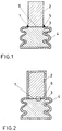
- FIG. 1 and 2 and each as Turbine blade 1 designed components each contain one elongated airfoil 2 and one at one end of the Blade 2 molded blade root 3.
- Reference numeral 4 denotes a press can.
- This Press can encloses the in the embodiment according to Fig.1 Blade root 3 and has one filled by the blade 2 Opening 5, which is preferably by welding or Soldering the press can 4 to the airfoil 2 gas-tight is completed.
- the press can 4 encloses the entire turbine blade 1.
- the turbine blade 1 shown in FIG. 1 is produced as follows: A cast body designed as an airfoil 2 is guided with its one end through the opening 5 into the press can 4.
- the press can 4 which is preferably made of steel, is soldered or welded to the cast body in a gas-tight manner in the region of the opening 5.
- a cavity of the press can which accommodates the blade root of the turbine blade 1, is filled with alloy powder.
- the press can 4 is then evacuated and sealed gas-tight.
- Doped gamma titanium aluminides are used as the material for the cast body and for the powder alloys based on Titanium or nickel used.
- the one that forms the cast body Alloy is advantageously a gamma titanium aluminide with one Proportion of at least 0.5 and at most 8 atomic percent Dopant, such as one or more of the elements B, C, Co, Cr, Ge, Hf, Mn, Mo, Nb, Pd, Si, Ta, V, Y, W and Zr.
- a typical alloy is 48 Atomic percent Al, 2 to 4 atomic percent chromium and the rest besides has unavoidable impurities Ti.
- Typical alloys included in addition to unavoidable impurities and Ti either 6 Atomic percent Al and 4 atomic percent V or 24 atomic percent Al and 11 atomic percent Nb.
- the nickel-based alloy used in the form of powder can for example the alloy IN 792 (composition in Weight percent Ni -0.12 C - 12.4 Cr - 9.0 Co - 1.9 Mo - 3.8 W - 3.9 Ta - 3.1 Al - 4.5 Ti - 0.2 B - 0.1 Zr).
- the size of the powder particles is for all powders used less than 500 ⁇ m.
- Such titanium and nickel-based alloys are characterized by good ductility (> 10%) Room temperature.
- the mechanical resistance of the titanium base alloys however, this is not the case at high temperatures as high as that of gamma titanium aluminides.
- Nickel based alloys however, have a much higher density than gamma titanium aluminides.
- the finished by gas-tight closing of the press jug 4 Sample was placed in a press and at Use of a titanium base alloy at temperatures between 900 and 980 ° C hot isostatically compressed.
- a typical one Pressing process at approx. 950 ° C lasted at a pressure of approx. 200 MPa about 3 hours.
- the two alloys were under Formation of a boundary layer 6 pore-free to a bimetallic Composite material compressed.
- the structure and the are from the micrograph according to FIG Microstructure of a part of the frame indicated in Fig. 2 To remove turbine blade according to the invention. From this is it can be seen that the alloy forming the airfoil 2 a coarse-grained alloy that forms the blade root 3 has a fine-grained microstructure and that the boundary layer 6 connecting both alloys is almost unstructured and according to chemical analysis in the essentially of a binary TiAl alloy with a proportion of approximately 25 atomic percent Al is formed.
- the alloy forming the airfoil 2 has a ductility of approximately 0.5 to 1% at room temperature, while the alloy forming the airfoil 3 has a ductility of 18 to 20%. At a temperature of approximately 700 ° C., the airfoil 2 has a creep resistance which is considerably higher than the creep resistance of the nickel-base superalloys usually used in this temperature range.
- the turbine blade 1 shows a ductility of 0.5 to 1% corresponding to the material of the blade leaf 2, which means that the ductility of the blade is not negatively influenced by the boundary layer 6.
- the turbine blade 1 according to the invention is therefore characterized by a blade root 3 with high ductility and an airfoil 2 which is brittle at room temperature but has a high creep resistance at high temperatures.
- the strength of the boundary layer 6 is sufficient to ensure safe operation of the turbine blade 1 at high temperatures.
- a body made of a hot isostatic compacted powder are introduced.
- a body made of a hot isostatic compacted powder were approximately 100 g an alloy powder with 48 atom percent Al, 3 atom percent Cr, balance Ti and small amounts of impurities Temperatures between 1050 and 1300 ° C and a pressure of approx. 250 MPa hot isostatically compressed for approx. 3 hours. The compacted powder was then at temperatures heat treated between 1300 and 1400 ° C for a few hours. Of the resulting body was then shown in Figure 2 Press can 4 brought and at those described there Conditions together with that forming the blade root 3 Powder is hot isostatically compressed. The according to that Heat treatment and corresponding post-processing resulting turbine blade pointed towards the Turbine blade according to Figure 2 with consistently good Creep resistance increased ductility by approx. 50% Blade 2 at room temperature.
- the Gamma titanium aluminide existing blade one blade root 3 molded from a nickel-based alloy.
- the Press can 4 was evacuated and sealed gas-tight.
- hot isostatic pressing for approx. 3 hours at approx. 1000 up to 1250 ° C and a pressure of approx. 250 MPa pore-free bimetallic composite material made from after removing the press can 4, after heat treatment approx. 700 ° to 800 ° C and post-processing to remove material a turbine blade was manufactured according to the invention. At this turbine blade showed the boundary layer 6 in particular good strength.
- a press can 4 as a form for receiving the alloys to use a sintered mold, and compacting to Achieve turbine blade in a sintering process.
- the invention is not limited to turbine blades. she also refers to others mechanically at high temperatures heavily loaded components, such as integrally formed Turbocharger turbine wheels.
Description
Bei der Erfindung wird ausgegangen von einem Bauteil für hohe
Temperaturen, insbesondere von einer Turbinenschaufel, gemäss
dem einleitenden Teil von Patentanspruch 1.The invention is based on a component for high
Temperatures, in particular from a turbine blade, according to
the introductory part of
Ein solches Bauteil und ein Verfahren zur Herstellung eines solchen Bauteils sind in DE 28 13 892 A1 beschrieben. Das beschriebene Bauteil ist als Turbinenlaufrad ausgebildet, welches durch Heisspressen von Metallpulvern mit unterschiedlichen Teilchenstrukturen und unterschiedlichen chemischen Zusammensetzungen hergestellt worden ist. Bei diesem Turbinenlaufrad wurde als Ausgangsmaterial für die Schaufeln mechanisch vorbehandeltes Pulver einer Nickelbasis-Superlegierung, wie beispielsweise der Legierung IN 792, mit Teilchen in Form abgeplatteter Kügelchen verwendet. Als Ausgangsmaterial für die Laufradscheibe wurde ein mechanisch nicht vorbehandeltes Pulver einer anderen Nickelbasis-Superlegierung, wie beispielsweise der Legierung IN 100, mit kugelförmigen Teilchen verwendet. Aufgrund der Struktur und der chemischen Zusammensetzung der Ausgangspulver zeichnen sich die Schaufeln durch eine gute Korrosionsbeständigkeit bei hohen Temperaturen aus und weist die Laufradscheibe eine hohe Zugfestigkeit und eine gute Ermüdungsbeständigkeit auf. Als Ausgangsmaterialien für das Turbinenlaufrad sind jedoch nur Legierungen geeignet, die wie die einander sehr verwandten Nickelbasis-Superlegierungen ohne Veränderung ihrer Gefüge und damit ihrer Eigenschaften den hohen Temperaturen beim heissisostatischen Pressen ausgesetzt werden können. Daher können bei der Herstellung dieses Turbinenlaufrades keine Legierungen verwendet werden, die zwar je für sich hervorragende Eigenschaften für unterschiedliche Aufgaben aufweisen, welche aber nur bei erheblich voneinander abweichenden Temperaturen heissverdichtet werden können.Such a component and a method for producing a such a component are described in DE 28 13 892 A1. The Component described is designed as a turbine impeller, which is achieved by hot pressing metal powders with different Particle structures and different chemical Compositions has been made. With this turbine impeller was mechanical as a starting material for the blades pretreated powder of a nickel base superalloy, such as for example the alloy IN 792, with particles in the form flattened beads used. As starting material for the Impeller was a mechanically not pretreated powder another nickel-based superalloy, such as of alloy IN 100, used with spherical particles. Due to the structure and chemical composition of the The powder is characterized by a good starting powder Corrosion resistance at high temperatures the impeller disc has high tensile strength and good Fatigue resistance. As starting materials for the Turbine impellers are, however, only suitable alloys that like the very related nickel-based superalloys without Changing their structure and thus their properties exposed to high temperatures during hot isostatic pressing can be. Therefore, when making this Alloys are not used for the turbine impeller excellent properties for different ones Have tasks, but only if they differ considerably deviating temperatures can be hot compressed.
Der Erfindung, wie sie in den Patentansprüchen 1 und 5 angegeben
ist, liegt die Aufgabe zugrunde, ein Bauteil, insbesondere
eine Turbinenschaufel, der eingangs genannten Art anzugeben,
welche sich bei Einsatz in einer bei hohen Temperaturen betriebenen
Vorrichtung, wie insbesondere einer Gasturbine, durch
eine hohe Lebensdauer auszeichnet, und gleichzeitig einen Weg
zu weisen, der es ermöglicht, ein solches Bauteil in einfacher
und für eine Massenfertigung geeigneten Weise herzustellen.The invention as specified in
Das Bauteil nach der Erfindung zeichnet sich gegenüber vergleichbaren Bauteilen nach dem Stand der Technik durch eine hohe Lebensdauer aus. Dies ist zum einen dadurch bedingt, dass unterschiedlich beanspruchte Teile des Bauteils aus unterschiedlich spezifizierten Legierungen bestehen, welche an die unterschiedlichen Beanspruchungen der Teile des Bauteils angepasst sind. Zum anderen sind diese Legierungen so ausgewählt, dass sie beim Heissverdichten zu einem bimetallischen Verbundwerkstoff eine Grenzschicht hoher Festigkeit bilden. Das Bauteil nach der Erfindung kann daher mit grosser Sicherheit hohe thermische und mechanische Belastungen aufnehmen, wie sie etwa bei Betrieb einer Gasturbine oder eines Verdichters eines Turboladers auftreten.The component according to the invention is distinguished from comparable Components according to the state of the art by long service life. On the one hand, this is due to the fact that differently stressed parts of the component from different specified alloys exist, which correspond to the different stresses on the parts of the component are adjusted. Secondly, these alloys are selected that when hot compacting it becomes a bimetallic Composite material form a boundary layer of high strength. The Component according to the invention can therefore with great certainty absorb high thermal and mechanical loads, as they do for example when operating a gas turbine or a compressor Turbocharger occur.
Das zur Herstellung der erfindungsgemässen Bauteile verwendete Verfahren zeichnet sich dadurch aus, dass das Heissverdichten bei Temperaturen ausgeführt wird, bei denen die für die angestrebten pysikalischen oder chemischen Eigenschaften erwünschten Gefüge der Legierungen auch dann mit grosser Sicherheit vorliegen, wenn die die Ausgangspulver bildenden Legierungen stark voneinander abweichende chemische Zusammensetzungen aufweisen.The one used to manufacture the components according to the invention The process is characterized in that the hot compression is carried out at temperatures at which the for desired physical or chemical properties desired structure of the alloys even with a large one Certainty is present if the ones that form the starting powder Alloys are very different chemical Have compositions.
Bevorzugte Ausführungsbeispiele der Erfindung und die damit erzielbaren Vorteile werden nachfolgend anhand von Zeichnungen näher erläutert. Hierbei zeigt:
- Fig.1
- eine Aufsicht auf einen in Längsrichtung geführten Schnitt durch eine erste Variante eines als Turbinenschaufel ausgeführten erfindungsgemässen Bauteils nach Beendigung eines beim Herstellverfahren ausgeführten heiss-isostatischen Pressvorganges,
- Fig.2
- eine Aufsicht auf einen in Längsrichtung geführten Schnitt durch eine zweite Variante eines als Turbinenschaufel ausgeführten erfindungsgemässen Bauteils nach Beendigung eines beim Herstellen ausgeführten heiss-isostatischen Pressvorganges, und
- Fig.3
- ein Schliffbild des umrandet angegebenen Bereichs der zweiten Variante des erfindungsgemässen Bauteils.
- Fig. 1
- 1 shows a plan view of a longitudinal section through a first variant of a component according to the invention designed as a turbine blade after completion of a hot isostatic pressing process carried out during the manufacturing process,
- Fig. 2
- a top view of a longitudinal section through a second variant of a component according to the invention designed as a turbine blade after completion of a hot isostatic pressing process carried out during manufacture, and
- Fig. 3
- a micrograph of the outlined area of the second variant of the component according to the invention.
Die in den Figuren 1 und 2 dargestellten und jeweils als
Turbinenschaufel 1 ausgebildeten Bauteile enthalten jeweils ein
langgestrecktes Schaufelblatt 2 und einen an einem Ende des
Schaufelblattes 2 angeformten Schaufelfuss 3. Mit dem
Bezugszeichen 4 ist eine Presskanne bezeichnet. Diese
Presskanne umschliesst bei der Ausführungsform gemäss Fig.1 den
Schaufelfuss 3 und weist eine vom Schaufelblatt 2 ausgefüllte
Öffnung 5 auf, welche vorzugsweise durch Anschweissen oder
Anlöten der Presskanne 4 an das Schaufelblatt 2 gasdicht
abgeschlossen ist. Bei der Ausführungsform gemäss Fig.2
umschliesst die Presskanne 4 die gesamte Turbinenschaufel 1.The shown in Figures 1 and 2 and each as
Die in Fig.1 dargestellte Turbinenschaufel 1 wird wie folgt
hergestellt:
Ein als Schaufelblatt 2 ausgeführter Gusskörper wird mit seinem
einen Ende durch die Öffnung 5 in die Presskanne 4 geführt. Die
vorzugsweise aus Stahl bestehende Presskanne 4 wird im Bereich
der Öffnung 5 gasdicht an den Gusskörper angelötet oder angeschweisst.
Durch eine nicht dargestellte weitere Öffnung der
Presskanne 4 wird ein den Schaufelfuss der Turbinenschaufel 1
aufnehmender Hohlraum der Presskanne mit Legierungspulver
aufgefüllt. Die Presskanne 4 wird sodann evakuiert und gasdicht
verschlossen.The
A cast body designed as an
Als Werkstoff für den Gusskörper werden dotierte gamma-Titanaluminide und für das Pulver Legierungen auf der Basis von Titan oder Nickel verwendet. Die den Gusskörper bildende Legierung ist mit Vorteil ein gamma-Titanaluminid mit einen Anteil von mindestens 0,5 und höchstens 8 Atomprozent an Dotierstoff, wie beispielsweise eines oder mehrere der Elemente B, C, Co, Cr, Ge, Hf, Mn, Mo, Nb, Pd, Si, Ta, V, Y, W sowie Zr. Eine typische Legierung ist beispielsweise eine solche, die 48 Atomprozent Al, 2 bis 4 Atomprozent Chrom und als Rest neben nicht zu vermeidenden Verunreinigungen Ti aufweist. Besonders bewährt hat sich eine Legierung mit der nachfolgend angegebene Zusammensetzung in Gewichtsprozent 33,2 Al - 3,9 Cr - Verunreinigungen kleiner 0,5 - Rest Ti. Gamma-Titanaluminide zeichnen sich durch eine geringe Dichte und eine gute mechanische Beständigkeit bei Temperaturen von bis zu 800°C aus. Jedoch ist ihre Duktilität vergleichsweise gering (<4%). Doped gamma titanium aluminides are used as the material for the cast body and for the powder alloys based on Titanium or nickel used. The one that forms the cast body Alloy is advantageously a gamma titanium aluminide with one Proportion of at least 0.5 and at most 8 atomic percent Dopant, such as one or more of the elements B, C, Co, Cr, Ge, Hf, Mn, Mo, Nb, Pd, Si, Ta, V, Y, W and Zr. For example, a typical alloy is 48 Atomic percent Al, 2 to 4 atomic percent chromium and the rest besides has unavoidable impurities Ti. Especially An alloy with the following value has proven itself Composition in percent by weight 33.2 Al - 3.9 Cr - Impurities less than 0.5 - balance Ti. Gamma titanium aluminides are characterized by a low density and good mechanical resistance at temperatures up to 800 ° C out. However, their ductility is comparatively low (<4%).
Die in Form von Pulver verwendete Titan-Basislegierung enthält neben dem Titan Aluminium und einen Anteil an bis zu 20 Atomprozent eines oder mehrerer Zusatzelemente, wie insbesondere V und/oder Nb. Typische Legierungen enthalten neben nicht zu vermeidenden Verunreinigungen und Ti entweder 6 Atomprozent Al und 4 Atomprozent V oder 24 Atomprozent Al und 11 Atomprozent Nb.Contains the titanium base alloy used in the form of powder in addition to the titanium aluminum and a share of up to 20 Atomic percent of one or more additional elements, such as especially V and / or Nb. Typical alloys included in addition to unavoidable impurities and Ti either 6 Atomic percent Al and 4 atomic percent V or 24 atomic percent Al and 11 atomic percent Nb.
Die in Form von Pulver verwendete Nickel-Basislegierung kann beispielsweise die Legierung IN 792 sein (Zusammensetzung in Gewichtsprozent Ni -0,12 C - 12,4 Cr - 9,0 Co - 1,9 Mo - 3,8 W - 3,9 Ta - 3,1 Al - 4,5 Ti - 0,2 B - 0,1 Zr).The nickel-based alloy used in the form of powder can for example the alloy IN 792 (composition in Weight percent Ni -0.12 C - 12.4 Cr - 9.0 Co - 1.9 Mo - 3.8 W - 3.9 Ta - 3.1 Al - 4.5 Ti - 0.2 B - 0.1 Zr).
Die Grösse der Pulverteilchen ist bei allen verwendeten Pulvern kleiner 500 µm. Derartige Titan- und Nickel- Basis-legierungen zeichnen sich durch eine gute Duktilität (>10%) bei Raumtemperatur aus. Die mechanische Beständigkeit der Titan-Basislegierungen bei hohen Temperaturen ist jedoch nicht so hoch wie jene von gamma-Titanaluminiden. Nickel-Basislegierungen hingegen weisen eine wesentlich höhere Dichte als gamma-Titanaluminide auf.The size of the powder particles is for all powders used less than 500 µm. Such titanium and nickel-based alloys are characterized by good ductility (> 10%) Room temperature. The mechanical resistance of the titanium base alloys however, this is not the case at high temperatures as high as that of gamma titanium aluminides. Nickel based alloys however, have a much higher density than gamma titanium aluminides.
Die durch gasdichtes Verschliessen der Presskanne 4 fertiggestellte
Probe wurde in eine Pressvorrichtung gebracht und bei
Verwendung einer Titan-Basislegierung bei Temperaturen zwischen
900 und 980°C heiss-isostatisch verdichtet. Ein typischer
Pressvorgang bei ca. 950°C dauerte bei einem Druck von ca. 200
MPa ca. 3 Stunden. Hierbei wurden die beiden Legierungen unter
Bildung einer Grenzschicht 6 porenfrei zu einem bimetallischen
Verbundwerkstoff verdichtet.The finished by gas-tight closing of the
Dieser bereits die Form der Turbinenschaufel aufweisende Verbundwerkstoff wurde nach Entfernen der deformierten Presskanne 4 sodann bei Temperaturen von ca. 700°C typischerweise ca. 4 Stunden lang wärmebehandelt. Nachfolgend wurde durch geringfügige materialabhebende Bearbeitung, wie Schleifen, Polieren und/oder elektrochemisches Behandeln, die Turbinenschaufel nach der Erfindung fertiggestellt.This already has the shape of the turbine blade Composite material was removed after removing the deformed press can 4 then typically at temperatures of approx. 700 ° C heat treated for about 4 hours. Subsequent was by minor processing, such as grinding, Polishing and / or electrochemical treatment, the Turbine blade according to the invention completed.
Bei der Herstellung der aus Fig.2 ersichtlichen Turbinenschaufel
1 wurde eine in Längsrichtung erweiterte und die
gesamte Turbinenschaufel 1 aufnehmende Presskanne 4 verwendet.
In diese Presskanne 4 wurde zunächst der das Schaufelblatt 2
bildende Gusskörper eingegeben und nachfolgend entsprechend dem
zuvor beschriebenen Ausführungsbeispiel das Legierungspulver
eingefüllt. Die Presskanne 4 wurde sodann evakuiert und gasdicht
verschlossen. Der so hergestellte Probekörper wurde
entsprechend dem zuvor beschriebenen Ausführungsbeispiel
behandelt. Die verwendeten Legierungen wiesen die gleiche
Zusammensetzung auf wie beim zuvor beschriebenen
Ausführungsbeispiel.In the manufacture of the turbine blade shown in FIG. 2
1 was extended in the longitudinal direction and the
Aus dem Schliffbild gemäss Fig.3 sind der Aufbau und die
Gefügestruktur eines in Fig.2 umrandet angegebenen Teils der
Turbinenschaufel nach der Erfindung zu entnehmen. Hieraus ist
ersichtlich, dass die das Schaufelblatt 2 bildende Legierung
eine grobkörnige und die den Schaufelfuss 3 bildende Legierung
eine feinkörnige Mikrostruktur aufweist, und dass die die
beiden Legierungen miteinander verbindende Grenzschicht 6
nahezu unstrukturiert ist und gemäss chemischer Analyse im
wesentlichen von einer binären TiAl-Legierung mit einem Anteil
von ca. 25 Atomprozent Al gebildet ist.The structure and the are from the micrograph according to FIG
Microstructure of a part of the frame indicated in Fig. 2
To remove turbine blade according to the invention. From this is
it can be seen that the alloy forming the airfoil 2
a coarse-grained alloy that forms the
Werkstoffuntersuchungen haben für den der erfindungsgemässen
Turbinenschaufel 1 zugrundeliegenden bimetallischen Verbundwerkstoff
folgende Eigenschaften ergeben:
Die das Schaufelblatt 2 bildende Legierung weist bei
Raumtemperatur eine Duktilität von ca. 0,5 bis 1% , die den
Schaufelfuss 3 bildende Legierung hingegen eine solche von 18
bis 20 % auf. Bei einer Temperatur von ca. 700°C besitzt das
Schaufelblatt 2 eine Kriechfestigkeit, welche erheblich über
der Kriechfestigkeit der üblicherweise in diesem
Temperaturbereich verwendeten Nickelbasis-Superlegierungen
liegt. Die Turbinenschaufel 1 zeigt eine dem Werkstoff des
Schaufelblattes 2 entsprechende Duktilität von 0.5 bis 1% auf,
was bedeutet, dass durch die Grenzschicht 6 die Duktilität der
Schaufel nicht negativ beeinflusst wird. Die Turbinenschaufel 1
nach der Erfindung zeichnet sich demnach durch einen Schaufelfuss
3 mit hoher Duktilität und ein bei Raumtemperatur zwar
sprödes, bei hohen Temperaturen jedoch eine grosse Kriechfestigkeit
aufweisendes Schaufelblatt 2 aus. Die Festigkeit der
Grenzschicht 6 reicht aus, um einen sicheren Betrieb der
Turbinenschaufel 1 bei hohen Temperaturen zu gewährleisten.Material tests have shown the following properties for the bimetallic composite material on which the
The alloy forming the
Eine erhöhte Festigkeit der Grenzschicht 6 kann dadurch
erreicht werden, dass die beiden Legierungen - wie in Fig.2
dargestellt - im Bereich der Grenzschicht 6 zumindest teilweise
oder aber vollständig ineinander verzahnt sind. Dies kann vor
dem Einbringen des Gusskörpers in die Presskanne 4 in einfacher
Weise durch Schleifen oder Sandstrahlen des Gusskörpers an
seinem den Schaufelfuss 3 aufnehmenden Ende bis zu einer
Rauhtiefe von bis zu 0.1 mm bewirkt werden.This can increase the strength of the
Anstelle eines das Schaufelblatt 2 bildenden Gusskörpers kann
in die Presskanne 4 auch ein Körper aus einem heiss-isostatisch
verdichteten Pulver eingeführt werden. In einer weiteren
alternativen Ausführungsform der Erfindung wurden ca. 100 g
eines Legierungspulvers mit 48 Atomprozent Al, 3 Atomprozent
Cr, Rest Ti und geringe Mengen an Verunreinigungen bei
Temperaturen zwischen 1050 und 1300°C und einem Druck von ca.
250 MPa während ca. 3 Stunden heiss-isostatisch verdichtet. Das
verdichtete Pulver wurde anschliessend bei Temperaturen
zwischen 1300 und 1400°C wenige Stunden wärmebehandelt. Der
resultierende Körper wurde sodann in die in Fig.2 dargestellte
Presskanne 4 gebracht und bei den dort beschriebenen
Bedingungen zusammen mit dem den Schaufelfuss 3 bildenden
Pulver heiss-isostatisch verdichtet. Die nach entsprechender
Wärmebehandlung und entsprechender Nachbearbeitung
resultierende Turbinenschaufel wies gegenüber der
Turbinenschaufel gemäss Fig.2 bei gleichbleibend guter
Kriechfestigkeit eine um ca. 50% erhöhte Duktilität des
Schaufelblattes 2 bei Raumtemperatur auf.Instead of a cast body forming the
In einer weiteren Variante der Erfindung wurde an das aus
gamma-Titanaluminid bestehende Schaufelblatt ein Schaufelfuss 3
aus einer Nickel-Basislegierung angeformt. Zu diesem Zweck
wurde in die bereits das Schaufelblatt enthaltende oder
alternativ in die an das Schaufelblatt angeschweisste
Presskanne 4 Pulver der Nickel-Basislegierung eingefüllt. Die
Presskanne 4 wurde evakuiert und gasdicht verschlossen. Durch
heiss-isostatisches Pressen während ca. 3 Stunden bei ca. 1000
bis 1250°C und einem Druck von ca. 250 MPa wurde ein
porenfreier bimetallischer Verbundwerkstoff hergestellt, aus
dem nach Entfernen der Presskanne 4, nach Wärmebehandeln bei
ca. 700° bis 800°C und materialentfernender Nachbearbeitung
eine Turbinenschaufel nach der Erfindung hergestellt wurde. Bei
dieser Turbinenschaufel wies die Grenzschicht 6 eine besonders
gute Festigkeit auf.In a further variant of the invention, the
Gamma titanium aluminide existing blade one
In einer weiteren Variante der Erfindung ist es möglich, an Stelle einer Presskanne 4 als Form zur Aufnahme der Legierungen eine Sinterform zu verwenden, und das Verdichten zur Turbinenschaufel in einem Sinterverfahren zu erreichen.In a further variant of the invention, it is possible to Place a press can 4 as a form for receiving the alloys to use a sintered mold, and compacting to Achieve turbine blade in a sintering process.
Die Erfindung ist nicht auf Turbinenschaufeln beschränkt. Sie bezieht sich auch auf andere bei hohen Temperaturen mechanisch stark belastete Bauteile, wie etwa einstückig ausgebildete Turbinenräder von Turboladern.The invention is not limited to turbine blades. she also refers to others mechanically at high temperatures heavily loaded components, such as integrally formed Turbocharger turbine wheels.
- 11
- TurbinenschaufelTurbine blade
- 22nd
- SchaufelblattAirfoil
- 33rd
- SchaufelfussBlade root
- 44th
- presskannepress jug
- 55
- Öffnungopening
- 66
- GrenzschichtBoundary layer
Claims (9)
- Component, in particular a turbine bucket (1), which can be exposed to high temperatures, having a component body comprising at least one first section (bucket footing 3) and at least one second section (bucket blade 2), in which component the first section (3) is formed by a ductile material and the second section (2) comprises a material which is brittle compared with the ductile material, and each of the two materials comprises one of two alloys of different chemical composition which have been hot-compacted with the formation of a boundary layer (6) joining the first (3) and the second section (2) to produce a bimetallic composite material, a first of the two alloys which forms the first section predominantly comprising titanium and/or nickel, and in that [sic] a second of the two alloys which forms the second section is a gamma-titanium aluminide and contains a proportion of at least 0.5 and at most 8 atomic per cent of dopant.
- Component according to Claim 1, wherein the second alloy comprises one or more of the elements B, C, Co, Cr, Ge, Hf, Mn, Mo, Nb, Pd, Si, Ta, V, Y, W and Zr as dopant.
- Component according to either of Claims 1 or 2, wherein the first alloy also comprises aluminum and vanadium or aluminum and niobium in addition to titanium.
- Component according to any of Claims 1 to 3, wherein the first and the second section are keyed into one another in the region of the boundary layer (6).
- Method of producing the component according to Claim 1, wherein, prior to the hot compacting, at least one end of a body cast from the second alloy or hot-compacted from powder of the second alloy is introduced into a mould constructed as pressing can (4) and in that the first alloy is poured into the pressing can as a powder and is brought into contact with the end of the body situated in the pressing can (4).
- Method according to Claim 5, wherein the pressing can (4) has an opening (5) which is filled by the body introduced and which is preferably sealed off by welding or soldering the pressing can (4) to the body.
- Method according to either of Claims 5 or 6, wherein the hot compacting is performed at temperatures of between 900 and 980°C if a first alloy based on titanium is used.
- Method according to either of Claims 5 or 6, wherein the hot compacting is performed at temperatures of between 1100 and 1250°C if a first alloy based on nickel is used.
- Method according to either of Claims 7 or 8, wherein the composite material produced by hot compacting is heat-treated at temperatures between 700 and 800°C.
Applications Claiming Priority (2)
| Application Number | Priority Date | Filing Date | Title |
|---|---|---|---|
| DE4219469 | 1992-06-13 | ||
| DE4219469A DE4219469A1 (en) | 1992-06-13 | 1992-06-13 | Component subject to high temperatures, in particular turbine blade, and method for producing this component |
Publications (2)
| Publication Number | Publication Date |
|---|---|
| EP0574727A1 EP0574727A1 (en) | 1993-12-22 |
| EP0574727B1 true EP0574727B1 (en) | 1998-08-26 |
Family
ID=6461000
Family Applications (1)
| Application Number | Title | Priority Date | Filing Date |
|---|---|---|---|
| EP93108243A Expired - Lifetime EP0574727B1 (en) | 1992-06-13 | 1993-05-21 | Method for the production of a high temperature-resistant element from two different materials |
Country Status (4)
| Country | Link |
|---|---|
| US (1) | US5395699A (en) |
| EP (1) | EP0574727B1 (en) |
| JP (1) | JPH06172816A (en) |
| DE (2) | DE4219469A1 (en) |
Cited By (1)
| Publication number | Priority date | Publication date | Assignee | Title |
|---|---|---|---|---|
| CN105014068A (en) * | 2015-08-06 | 2015-11-04 | 潘桂枝 | Preparing method for thermometal composite material |
Families Citing this family (19)
| Publication number | Priority date | Publication date | Assignee | Title |
|---|---|---|---|---|
| US6551064B1 (en) | 1996-07-24 | 2003-04-22 | General Electric Company | Laser shock peened gas turbine engine intermetallic parts |
| DE19710592A1 (en) * | 1997-03-14 | 1998-09-17 | Forschungszentrum Juelich Gmbh | Oxidation resistant titanium-aluminium alloy |
| DE19756354B4 (en) * | 1997-12-18 | 2007-03-01 | Alstom | Shovel and method of making the blade |
| DE19933633A1 (en) * | 1999-07-17 | 2001-01-18 | Abb Alstom Power Ch Ag | High temperature titanium alloy for highly-stressed components of heat engines, comprises titanium, aluminum, and e.g. boron silicon and e.g. tungsten |
| DE10054229B4 (en) * | 2000-11-02 | 2018-06-28 | Ansaldo Energia Ip Uk Limited | High temperature alloy |
| US7566415B2 (en) * | 2002-11-18 | 2009-07-28 | Adma Products, Inc. | Method for manufacturing fully dense metal sheets and layered composites from reactive alloy powders |
| US6852273B2 (en) * | 2003-01-29 | 2005-02-08 | Adma Products, Inc. | High-strength metal aluminide-containing matrix composites and methods of manufacture the same |
| US7241416B2 (en) * | 2003-08-12 | 2007-07-10 | Borg Warner Inc. | Metal injection molded turbine rotor and metal injection molded shaft connection attachment thereto |
| US20060083653A1 (en) * | 2004-10-20 | 2006-04-20 | Gopal Das | Low porosity powder metallurgy produced components |
| US20070003416A1 (en) * | 2005-06-30 | 2007-01-04 | General Electric Company | Niobium silicide-based turbine components, and related methods for laser deposition |
| JP2008202544A (en) * | 2007-02-21 | 2008-09-04 | Mitsubishi Heavy Ind Ltd | Manufacturing method of rotor, and exhaust turbocharger having the rotor |
| EE05653B1 (en) | 2010-04-29 | 2013-04-15 | O� Skeleton Technologies | S Blue composite electrode for electric double layer capacitor |
| DE102010042889A1 (en) * | 2010-10-25 | 2012-04-26 | Manfred Renkel | Turbocharger component prepared from an intermetallic titanium aluminide-alloy, useful e.g. for manufacturing turbine components, comprises e.g. aluminum, rare earth metal, niobium, tungsten, tantalum or rhenium, oxygen, and titanium |
| US8944762B2 (en) | 2011-10-28 | 2015-02-03 | United Technologies Corporation | Spoked spacer for a gas turbine engine |
| US9938831B2 (en) | 2011-10-28 | 2018-04-10 | United Technologies Corporation | Spoked rotor for a gas turbine engine |
| US10315279B2 (en) | 2014-08-08 | 2019-06-11 | Siemens Aktiengesellschaft | Hot isostatic pressing system for the assembly of modular components usable in a turbine engine |
| US10422228B2 (en) | 2016-04-12 | 2019-09-24 | United Technologies Corporation | Manufacturing a monolithic component with discrete portions formed of different metals |
| US20190040749A1 (en) * | 2017-08-01 | 2019-02-07 | United Technologies Corporation | Method of fabricating a turbine blade |
| RU178967U1 (en) * | 2017-10-31 | 2018-04-24 | федеральное государственное бюджетное образовательное учреждение высшего образования "Уфимский государственный авиационный технический университет" | TURBO MACHINE BLADE FROM ALUMINUM ALLOY WITH A STRENGTHENING CARBON-CONTAINING LAYER |
Family Cites Families (42)
| Publication number | Priority date | Publication date | Assignee | Title |
|---|---|---|---|---|
| US2431660A (en) * | 1944-12-01 | 1947-11-25 | Bbc Brown Boveri & Cie | Turbine blade |
| GB608766A (en) * | 1944-12-01 | 1948-09-21 | Bbc Brown Boveri & Cie | Improvements in turbine blades |
| FR1052893A (en) * | 1951-02-07 | 1954-01-28 | Plansee Metallwerk | Turbine blade with high resistance to heat and to ignition usable in particular in gas turbines, and method of manufacture thereof |
| US2946680A (en) * | 1955-08-10 | 1960-07-26 | Thompson Ramo Wooldridge Inc | Powder metallurgy |
| AT309154B (en) * | 1970-11-24 | 1973-08-10 | Plansee Metallwerk | Material for turbine blades |
| CH544217A (en) * | 1971-04-08 | 1973-11-15 | Bbc Sulzer Turbomaschinen | Gas turbine blade |
| FR2149990A5 (en) * | 1971-08-09 | 1973-03-30 | Imp Metal Ind Kynoch Ltd | Metal parts prodn from several elements - eg for aircraft using process which reduces fatigue |
| US3940268A (en) * | 1973-04-12 | 1976-02-24 | Crucible Inc. | Method for producing rotor discs |
| US3992200A (en) * | 1975-04-07 | 1976-11-16 | Crucible Inc. | Method of hot pressing using a getter |
| US4063939A (en) * | 1975-06-27 | 1977-12-20 | Special Metals Corporation | Composite turbine wheel and process for making same |
| US4097276A (en) * | 1975-07-17 | 1978-06-27 | The Garrett Corporation | Low cost, high temperature turbine wheel and method of making the same |
| GB1582651A (en) * | 1977-04-01 | 1981-01-14 | Rolls Royce | Products formed by powder metallurgy and a method therefore |
| DE2737248C2 (en) * | 1977-08-18 | 1985-09-19 | MTU Motoren- und Turbinen-Union München GmbH, 8000 München | High strength component with a complex geometric shape and process for its manufacture |
| US4294615A (en) * | 1979-07-25 | 1981-10-13 | United Technologies Corporation | Titanium alloys of the TiAl type |
| US4323394A (en) * | 1979-08-06 | 1982-04-06 | Motoren-Und Turbinen-Union Munchen Gmbh | Method for manufacturing turborotors such as gas turbine rotor wheels, and wheel produced thereby |
| SE8000750L (en) * | 1980-01-30 | 1981-07-31 | Bulten Kanthal Ab | HEATHOLD FIXED MACHINE COMPONENT AND SET TO MAKE IT |
| DE3010299C2 (en) * | 1980-03-18 | 1981-07-30 | MTU Motoren- und Turbinen-Union München GmbH, 8000 München | Hot isostatic pressing capsule and hot isostatic pressing method using the capsule |
| US4663241A (en) * | 1980-09-08 | 1987-05-05 | United Technologies Corporation | Powder metal disk with selective fatigue strengthening |
| JPS57155338A (en) * | 1981-03-23 | 1982-09-25 | Hitachi Ltd | Metallic body with alloy coating resistant to corrosion and thermal shock |
| SE446606B (en) * | 1981-08-27 | 1986-09-29 | Stal Laval Turbin Ab | VIEW TO MANUFACTURE SHOOTING RINGS AND SHEETS WITH SHOVERS FOR ROTATING MACHINES LIKE COMPRESSORS OR TURBINES |
| GB2117799B (en) * | 1982-03-05 | 1985-11-27 | Rolls Royce | Composite ceramic metal components |
| US4526747A (en) * | 1982-03-18 | 1985-07-02 | Williams International Corporation | Process for fabricating parts such as gas turbine compressors |
| US4529452A (en) * | 1984-07-30 | 1985-07-16 | United Technologies Corporation | Process for fabricating multi-alloy components |
| DE3511673A1 (en) * | 1985-03-18 | 1986-09-18 | Josef Gartner & Co, 8883 Gundelfingen | Composite profile |
| US4680160A (en) * | 1985-12-11 | 1987-07-14 | Trw Inc. | Method of forming a rotor |
| DE3543831A1 (en) * | 1985-12-12 | 1987-07-02 | Aluminium Walzwerke Singen | COMPOSITE PROFILE, IN PARTICULAR COMPOSITE RAIL |
| US4787821A (en) * | 1987-04-10 | 1988-11-29 | Allied Signal Inc. | Dual alloy rotor |
| US4900635A (en) * | 1987-07-27 | 1990-02-13 | Williams International Corporation | Multi-alloy turbine rotor disk |
| JPS6447828A (en) * | 1987-08-12 | 1989-02-22 | Agency Ind Science Techn | Turbin disk by super plastic forging of different alloys |
| US4851053A (en) * | 1988-05-06 | 1989-07-25 | The United States Of America As Represented By The Secretary Of The Air Force | Method to produce dispersion strengthened titanium alloy articles with high creep resistance |
| US4828793A (en) * | 1988-05-06 | 1989-05-09 | United States Of America As Represented By The Secretary Of The Air Force | Method to produce titanium alloy articles with high fatigue and fracture resistance |
| US4897127A (en) * | 1988-10-03 | 1990-01-30 | General Electric Company | Rapidly solidified and heat-treated manganese and niobium-modified titanium aluminum alloys |
| US4904546A (en) * | 1989-04-03 | 1990-02-27 | General Electric Company | Material system for high temperature jet engine operation |
| US4916028A (en) * | 1989-07-28 | 1990-04-10 | General Electric Company | Gamma titanium aluminum alloys modified by carbon, chromium and niobium |
| CA2025272A1 (en) * | 1989-12-04 | 1991-06-05 | Shyh-Chin Huang | High-niobium titanium aluminide alloys |
| US5098653A (en) * | 1990-07-02 | 1992-03-24 | General Electric Company | Tantalum and chromium containing titanium aluminide rendered castable by boron inoculation |
| US5080860A (en) * | 1990-07-02 | 1992-01-14 | General Electric Company | Niobium and chromium containing titanium aluminide rendered castable by boron inoculations |
| DE59103639D1 (en) * | 1990-07-04 | 1995-01-12 | Asea Brown Boveri | Process for producing a workpiece from a dopant-containing alloy based on titanium aluminide. |
| US5113583A (en) * | 1990-09-14 | 1992-05-19 | United Technologies Corporation | Integrally bladed rotor fabrication |
| US5098484A (en) * | 1991-01-30 | 1992-03-24 | The United States Of America As Represented By The Secretary Of The Air Force | Method for producing very fine microstructures in titanium aluminide alloy powder compacts |
| EP0513407B1 (en) * | 1991-05-13 | 1995-07-19 | Asea Brown Boveri Ag | Method of manufacture of a turbine blade |
| US5226985A (en) * | 1992-01-22 | 1993-07-13 | The United States Of America As Represented By The Secretary Of The Air Force | Method to produce gamma titanium aluminide articles having improved properties |
-
1992
- 1992-06-13 DE DE4219469A patent/DE4219469A1/en not_active Withdrawn
-
1993
- 1993-05-21 DE DE59308916T patent/DE59308916D1/en not_active Expired - Fee Related
- 1993-05-21 EP EP93108243A patent/EP0574727B1/en not_active Expired - Lifetime
- 1993-06-04 US US08/070,942 patent/US5395699A/en not_active Expired - Fee Related
- 1993-06-10 JP JP5138728A patent/JPH06172816A/en active Pending
Cited By (1)
| Publication number | Priority date | Publication date | Assignee | Title |
|---|---|---|---|---|
| CN105014068A (en) * | 2015-08-06 | 2015-11-04 | 潘桂枝 | Preparing method for thermometal composite material |
Also Published As
| Publication number | Publication date |
|---|---|
| EP0574727A1 (en) | 1993-12-22 |
| DE4219469A1 (en) | 1993-12-16 |
| US5395699A (en) | 1995-03-07 |
| JPH06172816A (en) | 1994-06-21 |
| DE59308916D1 (en) | 1998-10-01 |
Similar Documents
| Publication | Publication Date | Title |
|---|---|---|
| EP0574727B1 (en) | Method for the production of a high temperature-resistant element from two different materials | |
| EP0513407B1 (en) | Method of manufacture of a turbine blade | |
| DE69935891T2 (en) | Method for producing an engine lift valve | |
| DE19681358B4 (en) | Powder mixture made of aluminum alloy and sintered aluminum alloys | |
| DE69628786T2 (en) | Iron aluminide for electrical resistance heating elements | |
| DE2503165C2 (en) | Process for the production of a sintered body with locally different material properties and application of the process | |
| EP3069802B1 (en) | Method for producing a component made of a compound material with a metal matrix and incorporated intermetallic phases | |
| EP0574708B1 (en) | Component for high temperatures, in particular turbine blade, and process for preparing this blade | |
| DE2542094A1 (en) | METAL POWDER, METAL POWDER TREATMENT METHOD, AND METAL POWDER MANUFACTURING METHOD | |
| DE2813892B2 (en) | Process for the powder-metallurgical production of a turbine blade or a one-piece turbine impeller as well as for powder pretreatment | |
| DE19756354B4 (en) | Shovel and method of making the blade | |
| DE60008116T2 (en) | Superalloy with optimized high-temperature performance in high-pressure turbine disks | |
| DE2401849A1 (en) | PROCESS FOR PRODUCING DEFORMED OBJECTS FROM A DISPERSION STRENGTHENED ALLOY | |
| EP2990141A1 (en) | Method for producing TiAl components | |
| DE102017215321A1 (en) | METHOD FOR PRODUCING A TITANALUMINIDE COMPONENT WITH A TEETH CORE AND COMPONENT PRODUCED ACCORDINGLY | |
| EP1568486A1 (en) | Method for manufacturing of workpieces or semifinished products containing titanium aluminide alloys and products made thereby | |
| DE4434515C2 (en) | Oxide dispersion strengthened alloy and components of gas turbines made from it | |
| DE2156440A1 (en) | Process for the production of workpieces from materials with different properties | |
| AT392432B (en) | METHOD FOR THE PRODUCTION OF WARM-CRAWL-RESISTANT SEMI-FINISHED PRODUCTS OR MOLDED PARTS FROM HIGH-MELTING METALS | |
| EP0570072B1 (en) | Method of producing a chromium-base alloy | |
| DE2421680A1 (en) | NICKEL-COBALT-IRON CAST ALLOY WITH LOW COEFFICIENT OF EXTENSION AND HIGH YIELD LIMIT | |
| DE1558805C3 (en) | Process for the production of deformed workpieces from dispersion-reinforced metals or alloys | |
| DE2200670B2 (en) | ||
| EP3238863A1 (en) | Method for producing a rotor blade for a fluid flow engine | |
| DE102004002714B3 (en) | To produce sintered components, of light metal alloys, the powder is compressed into a green compact to be give a low temperature sintering followed by further compression and high temperature sintering |
Legal Events
| Date | Code | Title | Description |
|---|---|---|---|
| PUAI | Public reference made under article 153(3) epc to a published international application that has entered the european phase |
Free format text: ORIGINAL CODE: 0009012 |
|
| AK | Designated contracting states |
Kind code of ref document: A1 Designated state(s): CH DE FR GB IT LI NL |
|
| 17P | Request for examination filed |
Effective date: 19940513 |
|
| GRAG | Despatch of communication of intention to grant |
Free format text: ORIGINAL CODE: EPIDOS AGRA |
|
| 17Q | First examination report despatched |
Effective date: 19970731 |
|
| GRAG | Despatch of communication of intention to grant |
Free format text: ORIGINAL CODE: EPIDOS AGRA |
|
| GRAH | Despatch of communication of intention to grant a patent |
Free format text: ORIGINAL CODE: EPIDOS IGRA |
|
| GRAH | Despatch of communication of intention to grant a patent |
Free format text: ORIGINAL CODE: EPIDOS IGRA |
|
| GRAA | (expected) grant |
Free format text: ORIGINAL CODE: 0009210 |
|
| RAP1 | Party data changed (applicant data changed or rights of an application transferred) |
Owner name: ASEA BROWN BOVERI AG |
|
| AK | Designated contracting states |
Kind code of ref document: B1 Designated state(s): CH DE FR GB IT LI NL |
|
| REG | Reference to a national code |
Ref country code: CH Ref legal event code: EP |
|
| REF | Corresponds to: |
Ref document number: 59308916 Country of ref document: DE Date of ref document: 19981001 |
|
| GBT | Gb: translation of ep patent filed (gb section 77(6)(a)/1977) |
Effective date: 19981027 |
|
| ET | Fr: translation filed | ||
| PLBE | No opposition filed within time limit |
Free format text: ORIGINAL CODE: 0009261 |
|
| STAA | Information on the status of an ep patent application or granted ep patent |
Free format text: STATUS: NO OPPOSITION FILED WITHIN TIME LIMIT |
|
| 26N | No opposition filed | ||
| PGFP | Annual fee paid to national office [announced via postgrant information from national office to epo] |
Ref country code: GB Payment date: 20010412 Year of fee payment: 9 |
|
| PGFP | Annual fee paid to national office [announced via postgrant information from national office to epo] |
Ref country code: CH Payment date: 20010418 Year of fee payment: 9 |
|
| PGFP | Annual fee paid to national office [announced via postgrant information from national office to epo] |
Ref country code: FR Payment date: 20010507 Year of fee payment: 9 |
|
| PGFP | Annual fee paid to national office [announced via postgrant information from national office to epo] |
Ref country code: NL Payment date: 20010509 Year of fee payment: 9 Ref country code: DE Payment date: 20010509 Year of fee payment: 9 |
|
| REG | Reference to a national code |
Ref country code: GB Ref legal event code: IF02 |
|
| NLS | Nl: assignments of ep-patents |
Owner name: ALSTOM |
|
| PG25 | Lapsed in a contracting state [announced via postgrant information from national office to epo] |
Ref country code: GB Free format text: LAPSE BECAUSE OF NON-PAYMENT OF DUE FEES Effective date: 20020521 |
|
| PG25 | Lapsed in a contracting state [announced via postgrant information from national office to epo] |
Ref country code: LI Free format text: LAPSE BECAUSE OF NON-PAYMENT OF DUE FEES Effective date: 20020531 Ref country code: CH Free format text: LAPSE BECAUSE OF NON-PAYMENT OF DUE FEES Effective date: 20020531 |
|
| PG25 | Lapsed in a contracting state [announced via postgrant information from national office to epo] |
Ref country code: NL Free format text: LAPSE BECAUSE OF NON-PAYMENT OF DUE FEES Effective date: 20021201 |
|
| PG25 | Lapsed in a contracting state [announced via postgrant information from national office to epo] |
Ref country code: DE Free format text: LAPSE BECAUSE OF NON-PAYMENT OF DUE FEES Effective date: 20021203 |
|
| GBPC | Gb: european patent ceased through non-payment of renewal fee |
Effective date: 20020521 |
|
| REG | Reference to a national code |
Ref country code: CH Ref legal event code: PL |
|
| PG25 | Lapsed in a contracting state [announced via postgrant information from national office to epo] |
Ref country code: FR Free format text: LAPSE BECAUSE OF NON-PAYMENT OF DUE FEES Effective date: 20030131 |
|
| NLV4 | Nl: lapsed or anulled due to non-payment of the annual fee |
Effective date: 20021201 |
|
| REG | Reference to a national code |
Ref country code: FR Ref legal event code: ST |
|
| PG25 | Lapsed in a contracting state [announced via postgrant information from national office to epo] |
Ref country code: IT Free format text: LAPSE BECAUSE OF NON-PAYMENT OF DUE FEES;WARNING: LAPSES OF ITALIAN PATENTS WITH EFFECTIVE DATE BEFORE 2007 MAY HAVE OCCURRED AT ANY TIME BEFORE 2007. THE CORRECT EFFECTIVE DATE MAY BE DIFFERENT FROM THE ONE RECORDED. Effective date: 20050521 |