EP0573830A1 - Hydraulic drawing system in a press - Google Patents
Hydraulic drawing system in a press Download PDFInfo
- Publication number
- EP0573830A1 EP0573830A1 EP93108242A EP93108242A EP0573830A1 EP 0573830 A1 EP0573830 A1 EP 0573830A1 EP 93108242 A EP93108242 A EP 93108242A EP 93108242 A EP93108242 A EP 93108242A EP 0573830 A1 EP0573830 A1 EP 0573830A1
- Authority
- EP
- European Patent Office
- Prior art keywords
- valve
- cylinder
- pressure
- check valve
- series
- Prior art date
- Legal status (The legal status is an assumption and is not a legal conclusion. Google has not performed a legal analysis and makes no representation as to the accuracy of the status listed.)
- Granted
Links
Images

Classifications
-
- B—PERFORMING OPERATIONS; TRANSPORTING
- B21—MECHANICAL METAL-WORKING WITHOUT ESSENTIALLY REMOVING MATERIAL; PUNCHING METAL
- B21D—WORKING OR PROCESSING OF SHEET METAL OR METAL TUBES, RODS OR PROFILES WITHOUT ESSENTIALLY REMOVING MATERIAL; PUNCHING METAL
- B21D24/00—Special deep-drawing arrangements in, or in connection with, presses
- B21D24/04—Blank holders; Mounting means therefor
- B21D24/08—Pneumatically or hydraulically loaded blank holders
-
- B—PERFORMING OPERATIONS; TRANSPORTING
- B21—MECHANICAL METAL-WORKING WITHOUT ESSENTIALLY REMOVING MATERIAL; PUNCHING METAL
- B21D—WORKING OR PROCESSING OF SHEET METAL OR METAL TUBES, RODS OR PROFILES WITHOUT ESSENTIALLY REMOVING MATERIAL; PUNCHING METAL
- B21D24/00—Special deep-drawing arrangements in, or in connection with, presses
- B21D24/10—Devices controlling or operating blank holders independently, or in conjunction with dies
- B21D24/14—Devices controlling or operating blank holders independently, or in conjunction with dies pneumatically or hydraulically
Abstract
Description
Die Erfindung betrifft eine hydraulische Zieheinrichtung für Blechformteile in einer Presse gemäß dem Oberbegriff des Patentanspruches 1, die vorzugsweise in einer Transferpresse einsetzbar ist. Nach der EP-PS 0173 755 ist eine Zieheinrichtung in einer Presse bekannt, bei der der Blechhalterdruck in den verschiedenen Andruckbereichen für das Ziehteil der Umformung angepaßt wird. Dazu ist fest in den Pressentisch eine Anzahl von Druckzylindern installiert. Die Kolbenstangen der Druckzylinder sind über eine auf alle Kolbenstangen gemeinsam wirkende Druckwange in Richtung der Auswerferbewegung verfahrbar. Dabei wirken die anderen Enden der Kolbenstangen von unten auf den Blechhalter. Der Zylinderraum jedes Druckzylinders auf der dem Blechhalter abgewandten Kolbenseite ist separat über je ein Proportionalventil mit der Ölwanne verbunden.The invention relates to a hydraulic drawing device for sheet metal parts in a press according to the preamble of
Weiterhin ist aus der DE-OS 38 07 683 ein Ziehapparat in Ziehstufen von Pressen bekannt, bei der im Pressentisch Zylindereinheiten befestigt sind, die jeweils aus einem Ziehzylinder und einem Auswerferzylinder bestehen. Die verlängerte Kolbenstange jedes Auswerferzylinders wirkt über einen Führungszylinder auf einzelne Druckplatten. Auf diesen Druckplatten stützen sich Druckstifte ab, die von unten gegen den Blechhalter wirken. Die Drücke in den Ziehzylindern sind voneinander unabhängig durch Proportionalventile einstellbar.Furthermore, from DE-OS 38 07 683 a drawing device in drawing stages of presses is known, in which cylinder units are attached to the press table, each consisting of a drawing cylinder and an ejector cylinder. The extended piston rod of each ejector cylinder acts on individual pressure plates via a guide cylinder. Push pins are supported on these pressure plates, which act against the sheet metal holder from below. The pressures in the drawing cylinders can be set independently of one another using proportional valves.
Diese Lösungen sind leckölbehaftet. Die Einleitung der Auswerfbewegung über Proportionalventiltechnik ruft eine Geschwindigkeit in den Einrichtungen hervor, die für die Maschinen als auch für die Bedienpersonen gefahrbringend sind. Bei langem Stillstand der Einrichtung ist durch Leckagen in den Proportionalventilen eine Kissenabwärtsbewegung möglich.These solutions are leaking. The initiation of the ejection movement by means of proportional valve technology causes a speed in the devices that are dangerous for the machines as well as for the operators. If the device is not used for a long time, leaks in the proportional valves can cause the cushion to move downwards.
Das Problem der Erfindung liegt darin, den jeweiligen Hydraulikkreislauf zur Kraftsteuerung und zur Wegsteuerung einer Zieheinrichtung leckölfrei zu gestalten, um ungewollte sicherheitsrelevante Hubbewegungen der Kissenplatte in beiden Bewegungsrichtungen auszuschließen und den Druckerhalt bei Unterbrechung des Ziehvorganges mit und ohne Stößelrückhub zu garantieren.The problem of the invention is to design the respective hydraulic circuit for force control and for the displacement control of a pulling device to be leak-free in order to exclude undesired safety-relevant lifting movements of the cushion plate in both directions of movement and to guarantee pressure retention when the pulling process is interrupted with and without a ram return stroke.
Erfindungsgemäß wird das durch die im kennzeichnenden Teil der Patentansprüche 1 oder 2 beschriebenen Merkmale erreicht.According to the invention this is achieved by the features described in the characterizing part of
Weitere detaillierte Ausgestaltungen der Erfindung sind in den Ansprüchen 3 bis 6 beschrieben.Further detailed embodiments of the invention are described in
Die Vorteile der Lösung bestehen zusätzlich darin, daß durch die Anordnung und Schaltung der Rückschlagventile und des Steuerventils für die Wegsteuerung der Zieheinrichtung bei Ausfall eines der vorgenannten Ventile die Presse den nächsten Hub nicht ausführt. Nach dem Halt des Stößels während des Ziehprozesses wird durch Druckerhaltung im Druckraum des Verdrängungszylinders und Lagepositionierung der Zieheinrichtung der Stößelrückhub, die Fortsetzung des Ziehprozesses und die Kombination beider Vorgänge unter Beibehaltung der erforderlichen Blechformteilequalität des begonnenen Ziehteiles möglich. Die Lösung läßt ohne zusätzliche Schaltungen gefährdungslos einen Eingriff in den Werkzeugraum bei jeglicher Ziehkissenstellung durch eine Bedienperson zu.The advantages of the solution also consist in the fact that the arrangement and switching of the check valves and the control valve for the displacement control of the drawing device in the event of failure of one of the aforementioned valves means that the press does not carry out the next stroke. After the plunger has stopped during the drawing process, maintaining the plunger return stroke, continuing the drawing process and combining both processes while maintaining the required sheet metal part quality of the drawn part is possible by maintaining pressure in the pressure chamber of the displacement cylinder and positioning the drawing device. The solution allows an operator to intervene in the tool room at any die cushion position without additional circuits.
Nachfolgend wird die Erfindung anhand von drei in den Figuren dargestellten Ausführungsbeispielen erläutert. Es zeigen:
- Fig. 1:
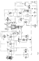
- Schaltung für Einpunkt-Ziehkissen mit zwei steuerbaren Druckräumen
- Fig. 2:
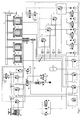
- Schaltung für Einpunkt-Ziehkissen mit drei steuerbaren Druckräumen
- Fig. 3:
- Schaltung für Vierpunkt-Ziehkissen mit zwei steuerbaren Druckräumen
- Fig. 1:
- Circuit for single-point die cushions with two controllable pressure rooms
- Fig. 2:
- Circuit for single-point die cushions with three controllable pressure rooms
- Fig. 3:
- Circuit for four-point die cushions with two controllable pressure chambers
Die Steuerung des Kissens beinhaltet gleichermaßen die Weg- und Kraftsteuerung der Kissenplatte 1, auf der sich in bekannter Weise die auf das Unterwerkzeug wirkenden Druckbolzen 23 abstützen. Dabei erfolgt die Beschreibung für einen Hubzyklus des Pressenstößels mit Zwischenhalt im Ziehbereich während des Vorhubes, anschließendem Rückhub des Stößels und nachfolgender Fortsetzung des Ziehvorganges nach Fig. 1. Dabei stellt die Vorabbeschleunigung eine zusätzliche Steuerung dar, die jedoch keine Notwendigkeit der vorgeschlagenen Lösung darstellt. Während des Stößelvor- hubes fährt der mit dem Stößel verbundene Anschlag 14 kurz vor Ziehbeginn nacheinander auf die Stufenkolben 25 der Kolben-Zylinder-Einheit 36 auf. Dadurch wird ein entsprechend der Querschnittsfläche der Stufenkolben 25 mit Stößelgeschwindigkeit zunehmender Ölstrom aus dem Stufenzylinder 13 über die in Reihe geschalteten Rückschlagventile 12 und 9 in den Sperrzylinder 3 zwangsweise gefördert. Dabei wird über den Sperrkolben 26 der mit einer Kolbenstange verbundene Verdrängerkolben 22 und die Kissenplatte 1 mit den Druckbolzen 23 in Ziehrichtung synchron zur jeweiligen Stößelgeschwindigkeit vorbeschleunigt. Das Flächenverhältnis aller Stufenkolben 25 zusammen zur wirksamen Ringfläche des Sperrkolbens 26 bestimmt dabei die erreichbare Geschwindigkeit zum Auftreffzeitpunkt des Oberwerkzeuges auf das Unterwerkzeug. Durch die Volumendosierung mittels Stößels wird neben der zeitlichen auch die wegabhängige Synchronisation zum Stößel erreicht.The control of the cushion likewise includes the displacement and force control of the
Abweichend vom festgelegten Flächenverhältnis zwischen der Summe der Stufenkolben 25 und der Ringfläche des Sperrkolbens 26 ermöglicht das parallel zum Rückschlagventil 15 in der Saugleitung zwischen Stufenzylinder 13 und Druckölquelle 17 angeordnete Proportionalventil 16, das vom Pressenantrieb gesteuert wird, während der Vorbeschleunigung einen variablen Nebenölstrom vom Stufenzylinder 25 zur Druckölquelle 17 und damit eine Veränderung der Kissenvorbeschleunigung.Deviating from the specified area ratio between the sum of the
Während der Kissenvorbeschleunigung bis zum Aufsetzen des Oberwerkzeuges auf das Unterwerkzeug wird das Öl vom Verdrängerkolben 22 aus dem Verdrängungszylinder 2 über das Rückschlagventil 7 zur Druckölquelle 17 befördert. Die weitere Hubbewegung des Kissens erfolgt stößelangetrieben, wodurch weiterhin Öl aus dem Verdrängungszylinder 2 verdrängt und in den Druckraum des Sperrzylinders 3 angesaugt wird. Die Ölverdrängung aus dem Verdrängungszylinder 2 erfolgt dabei in der bekannten Form über das Proportionalventil 8, dem von der Maschinensteuerung eine Solldruckfunktion in Abhängigkeit des Ziehweges zugeordnet ist, gemäß Anforderungsbild des Ziehwerkzeuges.During the cushion pre-acceleration until the upper tool is placed on the lower tool, the oil is transported from the
In der Leitung zwischen Verdrängungszylinder 2 und Proportionalventil 8 sind zusätzlich ein Druckmeßumformer 27 und ein in Richtung Proportionalventil öffnendes Rückschlagventil 6 angeordnet. Parallel hierzu ist zwischen Verdrängungszylinder 2 und Druckölquelle 17 ein in Richtung Druckölquelle öffnendes Rückschlagventil 7 angeordnet. Beide Rückschlagventile 6 und 7 werden durch das schaltende Wegeventil 4 und das Oder-Ventil 5 wechselseitig bzw. gleichzeitig in Fließrichtung leckölfrei gesperrt. Während des Ziehprozesses befindet sich das Wegeventil 4 in Schaltstellung a, wodurch das Rückschlagventil 7 den Abfluß zur Druckölquelle 17 sperrt und das Rückschlagventil 6 druckentlastet ist und damit freien Durchgang zum Proportionalventil 8 gewährt.A
Nach Anhalten des Pressenstößels während des Vorhubs im Ziehbereich wird das Wegeventil 4 von Schaltstellung a auf Schaltstellung b umgeschaltet. Dadurch wechselt die Druckentlastung vom Rückschlagventil 6 zum Rückschlagventil 7, was eine leckölfreie Absperrung vom Verdrängerzylinder 2 zum Proportionalventil 8 bedeutet, während der im Sperrzylinder 3 wirkende Auswerferdruck in der Druckölquelle 17 auch auf den Verdrängungszylinder 2 über das entlastete Rückschlagventil 7 übertragen wird. Das Kissen stützt sich mit Auswerferkraft am Stößel ab. Hierzu sind auch andere Varianten möglich.After stopping the press ram during the forward stroke in the drawing area, the
Vor der Fortsetzung des Ziehvorganges wird über einen Eingabebefehl die Leckölpumpe 19 eingeschaltet und geringfügig zeitversetzt ein Druckregelkreislauf aktiviert.Before the continuation of the drawing process, the
Dabei wird das Wegeventil 4 von Schaltstellung b auf Schaltstellung a umgeschaltet. Der vom Ziehweg abhängig gespeicherte Solldruck im Verdrängungszylinder 2 wird vom Druckmeßumformer 27 erfaßt und liefert den Sollwert an das Proportionalventil 8, welches gemäß Solldruck ausgeregelt wird. Über einen zweiten Eingabebefehl wird der Ziehvorgang fortgesetzt.The
Bei Unterbrechung des Ziehvorganges erfolgt der Steuerungsablauf folgendermaßen. Während des Tiefziehens strömt aus dem Verdrängungszylinder 2 das Öl über das Proportionalventil 8 zur Gegenkraftregelung ab und in den Sperrzylinder 3 strömt aus der Druckölquelle 17 Öl nach. Bei Stillstand des Pressenstößels schließt das Proportionalventil 8, um den Druck, der dem momentanen Ziehweg zugeordnet ist, auszuregeln. Dabei wirkt weiterhin die Druckölquelle 17 auf den Kolben des Sperrzylinders 3 und unterstützt durch die Massenkräfte wird das Kissen je nach Leckage des Proportionalventils 8 abwärts bewegt. Um dieser Abwärtsbewegung entgegenzuwirken, wird mit der Auslösung des Befehls zum Stößelhalt ein Signal an den Ölbehälter 20 übermittelt, das die Leckölpumpe 19 aktiviert.If the drawing process is interrupted, the control sequence is as follows. During the deep drawing, the oil flows out of the
Bleibt der Pressenstößel in seiner Stellung, stützt sich das Kissen an ihm ab und der aktuelle Druck wird in Abhängigkeit des Ziehweges (Sollprofil) geregelt. Bei Rückgang des Pressenstößels erfolgt an der Kolbenstange des Kissens ein Lastwechsel und das Ziehkissen stützt sich gegen die im Sperrzylinder 3 eingeschlossene Ölsäule ab. Der dort anstehende Druck ergibt sich aus dem zu regelnden Druck im Verdrängungszylinder 2 multipliziert mit dem Faktor des Flächenverhältnisses beider Ringflächen.If the press ram remains in its position, the cushion is supported on it and the current pressure is regulated depending on the drawing path (target profile). When the press ram falls, a load change occurs on the piston rod of the cushion and the die cushion is supported against the oil column enclosed in the
Bevor das Sicherheitsventil 29 anspricht, wird durch einen Druckschalter 38 ein Signal an den nicht dargestellten Regler übermittelt, das diesen von der Druck- in die Lageregelung schaltet. Der Sollwert für die Lageregelung soll im Augenblick des Stößelstillstandes ermittelt und gespeichert werden.Before the
Diese Lageregelung kann alternativ auch nach folgender Beschreibung erreicht werden. Bei Stillstand des Pressenstößels wird ein an sich bekannter Ausbalancierdruck eingestellt. Dieser Ausbalancierdruck verhindert ungewollte Entlastungsbewegungen bei Stößelrückgang und wird als Maschinenparameter (Blechhaltermasse, Masse des Kissenaggregates, Druck im Sperrzylinder) dem Regler als Sollwert für den Druckregelkreis übergeben sobald die Leckölpumpe 19 aktiviert ist. Er ist ausreichend groß, um das erfolgte Abheben des Stößels vom Kissen durch Druckanstieg im Sperrzylinder 3 erkennbar zu machen. Wird der Pressenstößel zurückgenommen, sorgt der Druckanstieg im Sperrzylinder 3 für das Schalten eines Rückschlagventiles 6,7, das zwischen Verdrängungszylinder 2 und Proportionalventil 8 angeordnet ist und leckölfrei sperrt. Setzt der Pressenstößel wieder auf, so erfolgt eine Entlastung des Sperrzylinders 3 in Verbindung mit einer erneuten Signalgabe zur Einstellung des Kissenzustandes, der kurz vor Unterbrechung des Ziehvorganges bestand.Alternatively, this position control can also be achieved according to the following description. When the press ram is at a standstill, a known balancing pressure is set. This balancing pressure prevents unwanted relief movements in the event of a tappet decline and is transferred to the controller as a machine parameter (sheet holder mass, mass of the cushion unit, pressure in the locking cylinder) as a setpoint for the pressure control circuit as soon as the
Zur exakten Fixierung der Kissenposition im Stillstand und in der Bewegung dient der mit der Kissensteuerung in Verbindung stehende Meßwertgeber 21. Kurz vor Erreichen der unteren Arbeitslage wird das Proportionalventil 8 in bekannter Weise kurzzeitig auf großen Austrittsquerschnitt gesteuert, wodurch der Druck im Verdrängungszylinder 2 sich in den Ölbehälter 20 entspannt. Gleichzeitig wirkt im Sperrzylinder 3 der Druck der Druckölquelle 17, der das Kissen nach unten zieht und eine Auffederung der Druckbolzen 23 nach dem Durchlaufen des unteren Totpunktes durch den Pressenstößel relativ zum Oberwerkzeug verhindert.For exact fixation of the cushion position during standstill and during movement, the
Im unteren Totpunkt des Stößels erfolgt die Umschaltung des Wegeventils 4 von Schaltstellung a auf Schaltstellung b, wodurch der Auswerferdruck der Druckölquelle 17 auf den Verdrängerkolben 22 freigegeben und gleichzeitig der Ölaustritt aus dem Verdrängungszylinder 2 durch das Rückschlagventil 6 abgesperrt wird. Das zwischen dem Sperrzylinder 3 und der Druckölquelle 17 in Reihe geschaltete Rückschlagventil 9 und Steuerventil 10, die jeweils wegüberwacht und als Sitzventil ausgebildet sind, gewährleisten eine leckölfreie Abdichtung des Sperrzylinders 3 und verhindern damit eine ungewollte Aufwärtsbewegung des Kissens. Ein von der Pressensteuerung variabel einstellbarer Schaltkontakt bewirkt die Umschaltung der Wegeventile 30 und 31 jeweils von Schaltstellung a auf Schaltstellung b wodurch das Rückschlagventil 9 und Steuerventil 10 geöffnet werden und der Auswerfvorgang eingeleitet wird. Das Steuerventil 10 ist in bekannter Weise als Sperr- und Drosselventil ausgebildet, dessen Drossel mittels pneumatisch beaufschlagtem Stellzylinder 32 und Druckregelventil 33 verändert werden kann und durch den Hebel 34, der mit dem Kissenanschlag 24 gekoppelt ist, bei oberen Kissenanschlag geschlossen wird.At the bottom dead center of the tappet, the
Die Drosselverstellung mittels Stellzylinder 32 ermöglicht die Einstellung unterschiedlicher Auswerfgeschwindigkeiten des Kissens bei variablen Auswerfkräften, während der Hebel 34 die zwangsgesteuerte Kissenanschlagdämpfung sichert. Während des Stößelrückhubes nach unterem Totpunkt löst sich der Anschlag 14 von den Stufenkolben 25, wodurch Öl aus der Druckölquelle 17 über das Rückschlagventil 15 in den Stufenzylinder 13 nachströmt und die Stufenkolben 25 in die Ausgangsstellung gelangen. Da die Summe der Fläche der Stufenzylinder 25 kleiner ist als die Ringfläche des Sperrkolbens 26, wird die Differenzölmenge während des Stößelvorlaufs von der Druckölquelle 17 über die in Reihe geschalteten, wegkontrollierten Rückschlagventile 11 und 9 nachgefördert.The throttle adjustment by means of the
Die paarweise Anordnung in Reihenschaltung, deren Ausbildung als Sitzventil mit elektrisch überwachter Lagekontrolle, die bei Ausfall je eines Ventils die Betriebsbereitschaft der Maschine unterbricht, schließt eine ungewollte Hubbewegung des Kissens aus. Dies betrifft die Rückschlagventile 12 und 9 in der Leitung 37 zwischen Kolben-Zylinder-Einheit 36 und Sperrzylinder 3, die Rückschlagventile 11 und 9 in der Nachsaugleitung zwischen Druckölquelle 17 und Sperrzylinder 3 sowie das Rückschlagventil 9 und Steuerventil 10 in der Verdrängerleitung zwischen Sperrzylinder 3 und Druckölquelle 17. Die Aufladung der Druckölquelle 17 erfolgt durch die Auswerferpumpe 18.The paired arrangement in series, their design as a seat valve with electrically monitored position control, which interrupts the operational readiness of the machine if one valve fails, precludes an unwanted lifting movement of the cushion. This applies to the
Im zweiten Ausführungsbeispiel gemäß Figur 2 sind die Funktionsräume für Verdrängen (Gegenhaltung) und Auswerfen gegenüber dem ersten Ausführungsbeispiel getrennt angeordnet. Der Auswerfzylinder 38 ist unterhalb des Sperrzylinders 3 angeordnet. Ein Vorteil dieser Anordnung besteht darin, daß kleinere Ölmengen mit höherem Druck zum Auswerfen genutzt werden können. Das Nachfüllen des Verdrängungszylinders 2 während des Auswerfens erfolgt aus dem mit niedrigem Pneumatikdruck vorgespannten Ausgleichszylinder 39, der in der Leitung zwischen den Rückschlagventilen 12 und 7 zugeschaltet ist.In the second exemplary embodiment according to FIG. 2, the functional spaces for displacement (counter-holding) and ejection are arranged separately from the first exemplary embodiment. The
Die prinzipielle Gestaltung und Wirkungsweise der erfindungsgemäßen Lösung entspricht dem ersten Ausführungsbeispiel.The basic design and mode of operation of the solution according to the invention corresponds to the first embodiment.
In der Figur 3 ist ein Mehrpunktziehkissen nach der vorgeschlagenen Lösung dargestellt. Je Ziehkissenpunkt ist zwischen Kissenplatte 1 und Tisch ein Verdrängungszylinder 2 mit Verdrängerkolben 22 angeordnet. Der Sperrzylinder 3 ist mittig mit der Kissenplatte 1 verbunden. In der Leitung 35 zwischen dem Druckraum jedes Verdrängungszylinders 2 und dem jeweils zugeordneten Proportionalventil 8 sind in Reihe ein schaltbares Rückschlagventil 6 und parallel dazu ein schaltbares Rückschlagventil 7 angeordnet, wobei ein Anschluß jedes Rückschlagventils 7 mit dem Rückschlagventil 12 wirkverbunden ist.FIG. 3 shows a multi-point pull pillow according to the proposed solution. A
Der weitere Aufbau entspricht identisch dem ersten Ausführungsbeispiel. Aber auch eine getrennte Anordnung der Funktionsräume für Verdrängen und Gegenhaltung nach Figur 2 ist möglich.The other structure corresponds identically to the first embodiment. However, a separate arrangement of the functional spaces for displacement and counter-holding according to FIG. 2 is also possible.
Die Wirkungsweise dieser Lösung erfolgt auch analog dem ersten Ausführungsbeispiel, so daß auch hier keine weitere Beschreibung erfolgt.The operation of this solution is also analogous to the first embodiment, so that no further description is given here either.
Claims (6)
dadurch gekennzeichnet,
characterized,
dadurch gekennzeichnet,
characterized,
dadurch gekennzeichnet,
daß der gemeinsame Steuerkreislauf für die Rückschlagventile (6, 7) derart gestaltet ist, daß in der Leitung 35 vor den Rückschlagventilen (6), (7) parallel ein Wegeventil (4) eingeordnet ist, wobei je ein Ventilausgang auf den jeweiligen Steueranschluß der Rückschlagventile (6), (7) geschaltet und der zweite Ventileingang mit dem Ölbehälter (20) wirkverbunden ist.Hydraulic pulling device according to claims 1 and 2
characterized,
that the common control circuit for the check valves (6, 7) is designed such that a directional valve (4) is arranged in parallel in line 35 before the check valves (6), (7), with one valve output each on the respective control connection of the check valves (6), (7) switched and the second valve input is operatively connected to the oil tank (20).
dadurch gekennzeichnet,
daß zwischen der Leitung 35 und dem Ventileingang des Wegeventils (4) ein Oder-Ventil (5) geschaltet ist, dessen zweiter Schaltausgang mit der Druckölquelle (17) in Wirkverbindung steht.Hydraulic pulling device according to claims 1, 2 and 3
characterized,
that an OR valve (5) is connected between the line 35 and the valve input of the directional valve (4), the second switching output of which is operatively connected to the pressure oil source (17).
dadurch gekennzeichnet,
daß in der Steuerleitung des Rückschlagventils (9) ein Wegeventil (30) zwischengeschaltet ist, dessen einer Ausgang mit dem Ölbehälter (20) wirkverbunden ist.Hydraulic pulling device according to claims 1 and 2
characterized,
that in the control line of the check valve (9) a directional valve (30) is interposed, one output of which is operatively connected to the oil tank (20).
dadurch gekennzeichnet,
daß zur Realisierung einer Vorbeschleunigung der Zieheinrichtung in der Leitung zwischen dem Rückschlagventil (12) und dem Druckausgleichsaggregat eine vom Pressenstößel betätigbare mehrstufige Kolben-Zylinder-Einheit (36) einordenbar ist.Hydraulic pulling device according to claims 1 and 2
characterized,
that a multi-stage piston-cylinder unit (36) which can be actuated by the press ram can be arranged in order to achieve a pre-acceleration of the drawing device in the line between the check valve (12) and the pressure compensation unit.
Applications Claiming Priority (2)
| Application Number | Priority Date | Filing Date | Title |
|---|---|---|---|
| DE4218914 | 1992-06-10 | ||
| DE4218914A DE4218914A1 (en) | 1992-06-10 | 1992-06-10 | Hydraulic pulling device in a press |
Publications (2)
| Publication Number | Publication Date |
|---|---|
| EP0573830A1 true EP0573830A1 (en) | 1993-12-15 |
| EP0573830B1 EP0573830B1 (en) | 1996-10-23 |
Family
ID=6460668
Family Applications (1)
| Application Number | Title | Priority Date | Filing Date |
|---|---|---|---|
| EP93108242A Expired - Lifetime EP0573830B1 (en) | 1992-06-10 | 1993-05-21 | Hydraulic drawing system in a press |
Country Status (3)
| Country | Link |
|---|---|
| EP (1) | EP0573830B1 (en) |
| DE (2) | DE4218914A1 (en) |
| ES (1) | ES2093315T3 (en) |
Cited By (2)
| Publication number | Priority date | Publication date | Assignee | Title |
|---|---|---|---|---|
| EP2335840A3 (en) * | 2009-12-15 | 2014-12-31 | Robert Bosch GmbH | Hydraulic press drive |
| CN106762886A (en) * | 2016-12-05 | 2017-05-31 | 重集团大连设计研究院有限公司 | Novel numerical control hydraulic pressure mattress system |
Families Citing this family (4)
| Publication number | Priority date | Publication date | Assignee | Title |
|---|---|---|---|---|
| DE4405909A1 (en) * | 1994-02-24 | 1995-08-31 | Erfurt Umformtechnik Gmbh | Method and circuit arrangement for interrupting and continuing the drawing process on double-acting presses, in particular hydraulic presses |
| JP4956022B2 (en) * | 2006-03-03 | 2012-06-20 | コマツ産機株式会社 | Die cushion control device for press machine |
| DE102015016773A1 (en) | 2015-12-23 | 2017-06-29 | Wieland Petter | Process for working and shaping metallic and other materials |
| DE102021101060B3 (en) | 2021-01-19 | 2022-05-05 | Johannes Hülshorst | deep drawing press |
Citations (4)
| Publication number | Priority date | Publication date | Assignee | Title |
|---|---|---|---|---|
| EP0173755A1 (en) * | 1984-06-29 | 1986-03-12 | L. SCHULER GmbH | Drawing device in a press |
| EP0268894A2 (en) * | 1986-11-28 | 1988-06-01 | L. SCHULER GmbH | Drawing device for a press |
| DE3807683A1 (en) * | 1988-03-09 | 1989-09-21 | Schuler Gmbh L | Drawing apparatus in drawing stages of presses |
| EP0406792A1 (en) * | 1989-07-06 | 1991-01-09 | L. SCHULER GmbH | Control switch connection for the upward stroke of the pressure cheek of a deep drawing device |
-
1992
- 1992-06-10 DE DE4218914A patent/DE4218914A1/en not_active Withdrawn
-
1993
- 1993-05-21 EP EP93108242A patent/EP0573830B1/en not_active Expired - Lifetime
- 1993-05-21 ES ES93108242T patent/ES2093315T3/en not_active Expired - Lifetime
- 1993-05-21 DE DE59304251T patent/DE59304251D1/en not_active Expired - Fee Related
Patent Citations (4)
| Publication number | Priority date | Publication date | Assignee | Title |
|---|---|---|---|---|
| EP0173755A1 (en) * | 1984-06-29 | 1986-03-12 | L. SCHULER GmbH | Drawing device in a press |
| EP0268894A2 (en) * | 1986-11-28 | 1988-06-01 | L. SCHULER GmbH | Drawing device for a press |
| DE3807683A1 (en) * | 1988-03-09 | 1989-09-21 | Schuler Gmbh L | Drawing apparatus in drawing stages of presses |
| EP0406792A1 (en) * | 1989-07-06 | 1991-01-09 | L. SCHULER GmbH | Control switch connection for the upward stroke of the pressure cheek of a deep drawing device |
Cited By (2)
| Publication number | Priority date | Publication date | Assignee | Title |
|---|---|---|---|---|
| EP2335840A3 (en) * | 2009-12-15 | 2014-12-31 | Robert Bosch GmbH | Hydraulic press drive |
| CN106762886A (en) * | 2016-12-05 | 2017-05-31 | 重集团大连设计研究院有限公司 | Novel numerical control hydraulic pressure mattress system |
Also Published As
| Publication number | Publication date |
|---|---|
| EP0573830B1 (en) | 1996-10-23 |
| DE4218914A1 (en) | 1993-12-16 |
| DE59304251D1 (en) | 1996-11-28 |
| ES2093315T3 (en) | 1996-12-16 |
Similar Documents
| Publication | Publication Date | Title |
|---|---|---|
| DE3640236C2 (en) | ||
| EP2384834B1 (en) | Hydraulic die cushion with a hydraulic cylinder | |
| CH662532A5 (en) | HYDRAULIC DEVICE FOR THE MOLDING UNIT OF A PLASTIC INJECTION MOLDING MACHINE. | |
| EP0268893A2 (en) | Drawing device for a press | |
| EP0173755B1 (en) | Drawing device in a press | |
| EP2183096A1 (en) | Drive system for hydraulic presses | |
| EP0573830B1 (en) | Hydraulic drawing system in a press | |
| DE3343172C2 (en) | ||
| EP0192115B1 (en) | Drawing apparatus for presses | |
| DE10336279A1 (en) | Device for controlling the drawing process in a transfer press | |
| DE4128610C2 (en) | Press arrangement with damping device and auxiliary device | |
| WO2010051913A1 (en) | Hydraulic force transducer | |
| DE4100716A1 (en) | Sheet metal hold-down device in single-acting press - has mechanical device to couple power transmission element | |
| EP1252010A1 (en) | Press | |
| DE4302263A1 (en) | Mechanical transfer press with hydraulic units | |
| DE19711780A1 (en) | Drawing device for drawing presses | |
| DE3619109C2 (en) | Impact shock absorbing device for die cushions on presses | |
| DE102004035590A1 (en) | Press with locked ram | |
| DE102011115508B4 (en) | Hydraulic ejector and multi-stage forge or press | |
| DE2432774B2 (en) | Press, especially fine blanking press | |
| EP0773076B1 (en) | Apparatus for controlling the pressure in hydraulic cushion devices of presses | |
| EP0406792A1 (en) | Control switch connection for the upward stroke of the pressure cheek of a deep drawing device | |
| DE2223708C3 (en) | Control for hydraulic open-die forging presses | |
| EP0564977B1 (en) | Run-up control system for the pressure cheek in a drawing apparatus | |
| EP0716916B1 (en) | Method for adjusting the impact of upper and lower tools in a press, damping the noise, and slide drive with a device using the method |
Legal Events
| Date | Code | Title | Description |
|---|---|---|---|
| PUAI | Public reference made under article 153(3) epc to a published international application that has entered the european phase |
Free format text: ORIGINAL CODE: 0009012 |
|
| AK | Designated contracting states |
Kind code of ref document: A1 Designated state(s): DE ES FR GB IT SE |
|
| 17P | Request for examination filed |
Effective date: 19940217 |
|
| GRAG | Despatch of communication of intention to grant |
Free format text: ORIGINAL CODE: EPIDOS AGRA |
|
| GRAH | Despatch of communication of intention to grant a patent |
Free format text: ORIGINAL CODE: EPIDOS IGRA |
|
| 17Q | First examination report despatched |
Effective date: 19960226 |
|
| GRAH | Despatch of communication of intention to grant a patent |
Free format text: ORIGINAL CODE: EPIDOS IGRA |
|
| GRAA | (expected) grant |
Free format text: ORIGINAL CODE: 0009210 |
|
| AK | Designated contracting states |
Kind code of ref document: B1 Designated state(s): DE ES FR GB IT SE |
|
| GBT | Gb: translation of ep patent filed (gb section 77(6)(a)/1977) |
Effective date: 19961023 |
|
| REF | Corresponds to: |
Ref document number: 59304251 Country of ref document: DE Date of ref document: 19961128 |
|
| REG | Reference to a national code |
Ref country code: ES Ref legal event code: FG2A Ref document number: 2093315 Country of ref document: ES Kind code of ref document: T3 |
|
| ITF | It: translation for a ep patent filed |
Owner name: SOCIETA' ITALIANA BREVETTI S.P.A. |
|
| ET | Fr: translation filed | ||
| PLBE | No opposition filed within time limit |
Free format text: ORIGINAL CODE: 0009261 |
|
| STAA | Information on the status of an ep patent application or granted ep patent |
Free format text: STATUS: NO OPPOSITION FILED WITHIN TIME LIMIT |
|
| 26N | No opposition filed | ||
| REG | Reference to a national code |
Ref country code: GB Ref legal event code: IF02 |
|
| PGFP | Annual fee paid to national office [announced via postgrant information from national office to epo] |
Ref country code: DE Payment date: 20050427 Year of fee payment: 13 |
|
| PGFP | Annual fee paid to national office [announced via postgrant information from national office to epo] |
Ref country code: GB Payment date: 20050512 Year of fee payment: 13 |
|
| PGFP | Annual fee paid to national office [announced via postgrant information from national office to epo] |
Ref country code: FR Payment date: 20050519 Year of fee payment: 13 |
|
| PGFP | Annual fee paid to national office [announced via postgrant information from national office to epo] |
Ref country code: SE Payment date: 20050524 Year of fee payment: 13 |
|
| PGFP | Annual fee paid to national office [announced via postgrant information from national office to epo] |
Ref country code: ES Payment date: 20050531 Year of fee payment: 13 |
|
| PG25 | Lapsed in a contracting state [announced via postgrant information from national office to epo] |
Ref country code: GB Free format text: LAPSE BECAUSE OF NON-PAYMENT OF DUE FEES Effective date: 20060521 |
|
| PG25 | Lapsed in a contracting state [announced via postgrant information from national office to epo] |
Ref country code: SE Free format text: LAPSE BECAUSE OF NON-PAYMENT OF DUE FEES Effective date: 20060522 Ref country code: ES Free format text: LAPSE BECAUSE OF NON-PAYMENT OF DUE FEES Effective date: 20060522 |
|
| PGFP | Annual fee paid to national office [announced via postgrant information from national office to epo] |
Ref country code: IT Payment date: 20060531 Year of fee payment: 14 |
|
| PG25 | Lapsed in a contracting state [announced via postgrant information from national office to epo] |
Ref country code: DE Free format text: LAPSE BECAUSE OF NON-PAYMENT OF DUE FEES Effective date: 20061201 |
|
| EUG | Se: european patent has lapsed | ||
| GBPC | Gb: european patent ceased through non-payment of renewal fee |
Effective date: 20060521 |
|
| REG | Reference to a national code |
Ref country code: FR Ref legal event code: ST Effective date: 20070131 |
|
| REG | Reference to a national code |
Ref country code: ES Ref legal event code: FD2A Effective date: 20060522 |
|
| PG25 | Lapsed in a contracting state [announced via postgrant information from national office to epo] |
Ref country code: FR Free format text: LAPSE BECAUSE OF NON-PAYMENT OF DUE FEES Effective date: 20060531 |
|
| PG25 | Lapsed in a contracting state [announced via postgrant information from national office to epo] |
Ref country code: IT Free format text: LAPSE BECAUSE OF NON-PAYMENT OF DUE FEES Effective date: 20070521 |